EP0843189A1 - Module autofocus - Google Patents
Module autofocus Download PDFInfo
- Publication number
- EP0843189A1 EP0843189A1 EP97203456A EP97203456A EP0843189A1 EP 0843189 A1 EP0843189 A1 EP 0843189A1 EP 97203456 A EP97203456 A EP 97203456A EP 97203456 A EP97203456 A EP 97203456A EP 0843189 A1 EP0843189 A1 EP 0843189A1
- Authority
- EP
- European Patent Office
- Prior art keywords
- pair
- autofocus module
- lens
- distance
- light
- Prior art date
- Legal status (The legal status is an assumption and is not a legal conclusion. Google has not performed a legal analysis and makes no representation as to the accuracy of the status listed.)
- Withdrawn
Links
- 239000004065 semiconductor Substances 0.000 claims 1
- 230000005855 radiation Effects 0.000 description 6
- 230000002596 correlated effect Effects 0.000 description 4
- 230000003287 optical effect Effects 0.000 description 4
- 238000005070 sampling Methods 0.000 description 4
- 230000004075 alteration Effects 0.000 description 3
- 238000005286 illumination Methods 0.000 description 3
- 238000002310 reflectometry Methods 0.000 description 3
- PPBRXRYQALVLMV-UHFFFAOYSA-N Styrene Chemical compound C=CC1=CC=CC=C1 PPBRXRYQALVLMV-UHFFFAOYSA-N 0.000 description 2
- NIXOWILDQLNWCW-UHFFFAOYSA-N acrylic acid group Chemical group C(C=C)(=O)O NIXOWILDQLNWCW-UHFFFAOYSA-N 0.000 description 2
- 238000010586 diagram Methods 0.000 description 2
- 238000006073 displacement reaction Methods 0.000 description 2
- 239000011521 glass Substances 0.000 description 2
- 238000005259 measurement Methods 0.000 description 2
- 238000013459 approach Methods 0.000 description 1
- 238000003491 array Methods 0.000 description 1
- 239000006185 dispersion Substances 0.000 description 1
- 230000000694 effects Effects 0.000 description 1
- 230000010354 integration Effects 0.000 description 1
- 238000012986 modification Methods 0.000 description 1
- 230000004048 modification Effects 0.000 description 1
- 238000012545 processing Methods 0.000 description 1
- 238000012552 review Methods 0.000 description 1
- 230000003595 spectral effect Effects 0.000 description 1
- 230000000007 visual effect Effects 0.000 description 1
Images





Classifications
-
- G—PHYSICS
- G02—OPTICS
- G02B—OPTICAL ELEMENTS, SYSTEMS OR APPARATUS
- G02B27/00—Optical systems or apparatus not provided for by any of the groups G02B1/00 - G02B26/00, G02B30/00
- G02B27/42—Diffraction optics, i.e. systems including a diffractive element being designed for providing a diffractive effect
- G02B27/4205—Diffraction optics, i.e. systems including a diffractive element being designed for providing a diffractive effect having a diffractive optical element [DOE] contributing to image formation, e.g. whereby modulation transfer function MTF or optical aberrations are relevant
- G02B27/4211—Diffraction optics, i.e. systems including a diffractive element being designed for providing a diffractive effect having a diffractive optical element [DOE] contributing to image formation, e.g. whereby modulation transfer function MTF or optical aberrations are relevant correcting chromatic aberrations
-
- G—PHYSICS
- G02—OPTICS
- G02B—OPTICAL ELEMENTS, SYSTEMS OR APPARATUS
- G02B27/00—Optical systems or apparatus not provided for by any of the groups G02B1/00 - G02B26/00, G02B30/00
- G02B27/0025—Optical systems or apparatus not provided for by any of the groups G02B1/00 - G02B26/00, G02B30/00 for optical correction, e.g. distorsion, aberration
- G02B27/0037—Optical systems or apparatus not provided for by any of the groups G02B1/00 - G02B26/00, G02B30/00 for optical correction, e.g. distorsion, aberration with diffracting elements
-
- G—PHYSICS
- G02—OPTICS
- G02B—OPTICAL ELEMENTS, SYSTEMS OR APPARATUS
- G02B3/00—Simple or compound lenses
- G02B3/02—Simple or compound lenses with non-spherical faces
- G02B3/06—Simple or compound lenses with non-spherical faces with cylindrical or toric faces
-
- G—PHYSICS
- G02—OPTICS
- G02B—OPTICAL ELEMENTS, SYSTEMS OR APPARATUS
- G02B7/00—Mountings, adjusting means, or light-tight connections, for optical elements
- G02B7/28—Systems for automatic generation of focusing signals
- G02B7/34—Systems for automatic generation of focusing signals using different areas in a pupil plane
- G02B7/346—Systems for automatic generation of focusing signals using different areas in a pupil plane using horizontal and vertical areas in the pupil plane, i.e. wide area autofocusing
Definitions
- This invention relates generally to the field of automatic focusing or rangefinding devices and more specifically to an electro-optical device which provides signals as a function of object distance.
- One approach that is of interest to the present invention uses one laser beam that is generally directed to the center of a camera's field of view.
- An object in the path of the laser beam reflects light which is received by the camera along two separate optical paths.
- One of the paths has a focal length that is different from the other in that when the lens is focusing the object onto the plane of the film the same object is being imaged onto photodetectors from the separate optical paths.
- the magnitude of the signals from the photodetectors in each path will be the same when the lens is focused.
- the signals from the photodetectors will have a difference indicating the difference in size of the illumination spot on the near and far channel photodetectors. That difference is indicative of the amount of defocus and the direction of the defocus.
- the passive triangulation system consists of two lenses with two associated photodetector arrays on which an image of the field of view of the camera is formed. By comparing the location of the intensity distribution along the horizontal direction of each photodetector array, with respect to the center of the photodetector array, the angular displacement of the two images from the centers of their associated photodetector array is known. Since the focal length of the receiver lens is known, the object's distance can be determined from the angular displacement of the light on the photodetector array and the focal length of the receiver lens.
- An active system additionally incorporates a radiation source such as one or more LEDs to project one or more spots of light onto the object to be photographed.
- a radiation source such as one or more LEDs to project one or more spots of light onto the object to be photographed.
- the angular position can be analyzed by using a CCD or photodetector array or by using a PSD (position sensitive diode).
- a system of extremely low cost is one that projects a non-focused light beam from an LED onto the object and measures the intensity of the returned light.
- An estimation of the distance to the object is made based on the assumption of all objects having an average reflectivity of 18%.
- an autofocus module comprising:
- the present invention has the following advantages:
- a radiation beam 30 from a source such as a laser diode 10 is shaped into a horizontal fan of radiation by a toroidal collimator (refractive/diffractive) lens 20 which has a longer focal length in the horizontal direction than in the vertical direction.
- the fan of radiation 30 reflects off of an object 50 and the reflected light is imaged by two receiver lenses 40 and 42 onto rectangular photodetectors 44 and 46, respectively.
- each of the photodetectors is formed with three sections that correspond to a right, a center, and a left section which allows the user to focus on objects in the right, center, or left portion of the field of view of the device.
- the operation of the autofocus module 100 can be understood by considering the difference in size of the defocused spots from a distant object 50 from two lenses 40 and 42, with focal lengths which are shorter and longer than the distance to the near and far channel photodetectors 44 and 46, respectively.
- the focal lengths of the near and far channel receiver lenses 40 and 42 are chosen so that the defocused spot sizes on the detectors are equal for an object located at the desired crossover location. In camera applications the crossover location is approximately 1520 mm (5 ft). As the object moves away from the camera the images formed by the near and far channel lenses 40 and 42 will move towards the focal points of each lens.
- the near channel lens 40 focal point is already in front of the detector plane of the photodetector 44 this will result in a larger defocused spot on the detector plane while the image from the far channel moves closer to the detector plane of the photodetector 46, and a smaller spot is formed on the detector plane.
- the detector aperture (determined by the size of the phodetector's photosensitive area) is fixed and is smaller than the defocused spot, the relative differences in spot sizes will translate into differences in the photocurrent from each photodetector which can then be translated into voltage differences which are proportional to the object's distance.
- the photodetectors may be located at different planes with the focal length of each receiver lens being the same.
- DB(z) rd rl ⁇ 1 - t ⁇ f + t z 2 - rd rl ⁇ 1 - t ⁇ n + t z 2
- the derived distance signal is usable, in a first embodiment, to drive the image capture lens to a focused position or in another embodiment the distance signal may be used to drive an indicator to provide a visual readout of distance such as would be required in a rangefinder device.
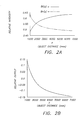
- the Fig. 2A curve Bf represents the output signal strength on the far channel as the object distance varies from 1,000 to approximately 7,000 mm.
- the curve Bn represents the object signal strength on the near channel as the object distance varies over the same range.
- the difference between the two channels is represented in Fig. 2B as an output signal that is proportional to object distance.
- the laser diode 10 emits an elliptical beam which is incident on the toroidal collimator lens 20.
- the rear surface 22 of the lens 20 is a spherical surface with a diffractive profile for achromatizing the toroidal collimator lens 20 over the wavelength band of interest.
- the front surface 24 of the lens 20 is a toroid which collimates the beam 30 in the vertical direction and allows the beam to diverge in the horizontal direction by approximately ⁇ 5 degrees.
- the radii of curvature of the front surface 24 in the vertical direction is shorter than the radius of curvature in the horizontal direction.
- an aspheric profile may be imparted to one or both of the surface curvatures on surface 24.
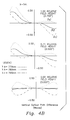
- Figures 4A and 4B show the ray aberration curves for the vertical and horizontal directions of the lens 20, respectively. As can be seen, the aberrations are generally less than 1/2 wave of optical path difference. In addition, one can see that the lens performs reasonably over a band of ⁇ 10 nm around the central wavelength (780 nm).
- Fig. 5A shows the location of diffractive profile maxima for the near channel receiver lens 40.
- the center of the diffractive profile does not occur at the center of clear aperture (intersection of axis A and B).
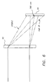
- This feature allows the light incident on the receiver lens 40 to be dispersed angularly as a function of wavelength. This in turn allows the laser illumination to be incident on the center of the photodetector while visible, and far infrared light from the object, is deflected outside of the photodetector aperture (see Fig. 6).
- This receiver lens 40 has a focal length of 14.7 mm and an f# of 1.8.
- the specification data for lens 40 is listed in the following table: Surface No.
- Figure 5B shows the location of diffractive profile maxima for the far channel receiver lens 42 which is also decentered and which has a focal length of 18.1 mm and an f# of 2.1.
- Figure 6 consists of a side view of the near channel receiver lens 40 showing the diffraction of infrared laser light (at 780 nm) into the aperture of the photodetector 44. Visible light or wavelengths from 400 to 700 nm is incident on the detector plane above the photodetector while far infrared light is diffracted below the photodetector. In this fashion the decentered diffractive element acts as a spectral filter to disperse light from the object not emitted by the laser diode from the aperture of the photodetector.
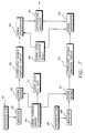
- a laser current driver 54 powers and modulates the laser diode 10 at a frequency of five kilohertz (5 khz).
- the output signals from the photodetectors 44 and 46 are amplified by amplifiers 56 and 58, respectively, and are processed in separate channels for comparison.
- the amplified signal of photodetector 44 is gated at 60 to a correlated double sampling circuit 62 and then forwarded to an integrator 64. Gating is controlled by a synchronization signal from the laser current driver 54.
- the integrating period of integrator 62 is matched to the "on" period of the laser diode 10.
- the signal from the photodetector 44 is inverted and integrated in the negative sense. This allows for the subtraction of photodetector dark current, ambient DC light, flicker, and 1/f noise.
- This embodiment includes the advantages of correlated double sampling for each signal channel. Noise is reduced, and the signal-to-noise ratio increased by integrating the amplified photodetector signal only when the laser diode 10 is "on.”
- the integrated signal from the second channel, 46, 58, 61, 63, and 65 is sampled and subtracted by a differencing stage 70.
- the output signal representing the direction and magnitude of focus adjustment required for a camera objective lens is independent of the absolute illumination from the laser and the reflectivity of the subject.
- the output signal can be analog or digital. If the output signal is digitized, its application in a microprocessor based system is simplified. The microprocessor can then direct a motor to move the camera objective lens to its in-focus position.
Landscapes
- Physics & Mathematics (AREA)
- General Physics & Mathematics (AREA)
- Optics & Photonics (AREA)
- Focusing (AREA)
- Automatic Focus Adjustment (AREA)
- Measurement Of Optical Distance (AREA)
Applications Claiming Priority (2)
| Application Number | Priority Date | Filing Date | Title |
|---|---|---|---|
| US748729 | 1991-08-22 | ||
| US08/748,729 US5703351A (en) | 1996-11-18 | 1996-11-18 | Autofocus module having a diffractively achromatized toroidal lens |
Publications (1)
| Publication Number | Publication Date |
|---|---|
| EP0843189A1 true EP0843189A1 (fr) | 1998-05-20 |
Family
ID=25010670
Family Applications (1)
| Application Number | Title | Priority Date | Filing Date |
|---|---|---|---|
| EP97203456A Withdrawn EP0843189A1 (fr) | 1996-11-18 | 1997-11-07 | Module autofocus |
Country Status (3)
| Country | Link |
|---|---|
| US (1) | US5703351A (fr) |
| EP (1) | EP0843189A1 (fr) |
| JP (1) | JPH10161008A (fr) |
Families Citing this family (30)
| Publication number | Priority date | Publication date | Assignee | Title |
|---|---|---|---|---|
| US5867522A (en) * | 1997-04-11 | 1999-02-02 | Spectra Precision, Inc. | Autofocusing system for a laser transmitter |
| US6812479B2 (en) * | 2001-06-05 | 2004-11-02 | Koninklijke Philips Electronics N.V. | Sample positioning method for surface optical diagnostics using video imaging |
| US6621060B1 (en) | 2002-03-29 | 2003-09-16 | Photonics Research Ontario | Autofocus feedback positioning system for laser processing |
| AT414174B (de) * | 2002-11-20 | 2006-09-15 | Wilfried Dr Lutz | Einrichtung zur abbildung von lichtquellen |
| JP2004361740A (ja) * | 2003-06-05 | 2004-12-24 | Canon Inc | 自動焦点調節装置及び方法 |
| JP4766841B2 (ja) * | 2003-09-08 | 2011-09-07 | 株式会社オートネットワーク技術研究所 | 車両に搭載されるカメラ装置及び車両周辺監視装置 |
| WO2012017267A1 (fr) * | 2010-08-03 | 2012-02-09 | Nokia Corporation | Détection de proximité optique |
| CN102313882B (zh) * | 2011-07-22 | 2015-07-29 | 江苏徕兹光电科技有限公司 | 激光测距仪的光学系统结构 |
| US8836922B1 (en) | 2013-08-20 | 2014-09-16 | Google Inc. | Devices and methods for a rotating LIDAR platform with a shared transmit/receive path |
| US20150116576A1 (en) * | 2013-10-30 | 2015-04-30 | Blackberry Limited | Image capture assembly, digital camera and a mobile device having an improved construction |
| JP6614909B2 (ja) * | 2015-10-15 | 2019-12-04 | アズビル株式会社 | 光電センサ |
| US9720415B2 (en) | 2015-11-04 | 2017-08-01 | Zoox, Inc. | Sensor-based object-detection optimization for autonomous vehicles |
| US10048358B2 (en) | 2016-12-30 | 2018-08-14 | Panosense Inc. | Laser power calibration and correction |
| US10742088B2 (en) | 2016-12-30 | 2020-08-11 | Panosense Inc. | Support assembly for rotating body |
| US11255951B1 (en) | 2016-12-30 | 2022-02-22 | Zoox, Inc. | Aligning optical components in LIDAR systems |
| US10122416B2 (en) | 2016-12-30 | 2018-11-06 | Panosense Inc. | Interface for transferring power and data between a non-rotating body and a rotating body |
| US10830878B2 (en) | 2016-12-30 | 2020-11-10 | Panosense Inc. | LIDAR system |
| US10591740B2 (en) | 2016-12-30 | 2020-03-17 | Panosense Inc. | Lens assembly for a LIDAR system |
| US10359507B2 (en) | 2016-12-30 | 2019-07-23 | Panosense Inc. | Lidar sensor assembly calibration based on reference surface |
| US10109183B1 (en) | 2016-12-30 | 2018-10-23 | Panosense Inc. | Interface for transferring data between a non-rotating body and a rotating body |
| US10338594B2 (en) * | 2017-03-13 | 2019-07-02 | Nio Usa, Inc. | Navigation of autonomous vehicles to enhance safety under one or more fault conditions |
| US10556585B1 (en) | 2017-04-13 | 2020-02-11 | Panosense Inc. | Surface normal determination for LIDAR range samples by detecting probe pulse stretching |
| US10423162B2 (en) | 2017-05-08 | 2019-09-24 | Nio Usa, Inc. | Autonomous vehicle logic to identify permissioned parking relative to multiple classes of restricted parking |
| US10710633B2 (en) | 2017-07-14 | 2020-07-14 | Nio Usa, Inc. | Control of complex parking maneuvers and autonomous fuel replenishment of driverless vehicles |
| US10369974B2 (en) | 2017-07-14 | 2019-08-06 | Nio Usa, Inc. | Control and coordination of driverless fuel replenishment for autonomous vehicles |
| CN111999878B (zh) * | 2017-11-16 | 2022-04-19 | 宁波舜宇仪器有限公司 | 一种显微成像系统及其实时对焦方法 |
| DE102017130012A1 (de) * | 2017-12-14 | 2019-06-19 | Arnold & Richter Cine Technik Gmbh & Co. Betriebs Kg | Kamerasystem mit laserbasiertem Rangefinder |
| US11022971B2 (en) | 2018-01-16 | 2021-06-01 | Nio Usa, Inc. | Event data recordation to identify and resolve anomalies associated with control of driverless vehicles |
| CN112368627B (zh) * | 2018-07-12 | 2022-07-29 | 深圳源光科技有限公司 | 光扫描仪 |
| JP7550221B2 (ja) * | 2020-05-15 | 2024-09-12 | ソニーセミコンダクタソリューションズ株式会社 | 光学モジュールおよび距離測定装置 |
Citations (5)
| Publication number | Priority date | Publication date | Assignee | Title |
|---|---|---|---|---|
| US4313654A (en) * | 1977-09-06 | 1982-02-02 | Minolta Camera Kabushiki Kaisha | Automatic rangefinder system for photographic camera with light emitting and receiving means |
| US4419011A (en) * | 1979-11-26 | 1983-12-06 | Minolta Camera Kabushiki Kaisha | Automatic range finder |
| JPS61246713A (ja) * | 1985-04-24 | 1986-11-04 | Fuji Photo Film Co Ltd | カメラ用受光センサ−及び露光制御方法 |
| GB2272125A (en) * | 1992-10-29 | 1994-05-04 | Seikosha Kk | Distance measurement |
| US5569904A (en) * | 1994-07-19 | 1996-10-29 | Eastman Kodak Company | Multispot autofocus system having a radiation emitter which emits radiation that is divided into a plurality of discrete beams |
Family Cites Families (4)
| Publication number | Priority date | Publication date | Assignee | Title |
|---|---|---|---|---|
| JPS5767904A (en) * | 1980-10-16 | 1982-04-24 | Canon Inc | Deciding system for adjusting state of focus |
| JPH01259313A (ja) * | 1988-04-11 | 1989-10-17 | Nikon Corp | カメラの測距装置 |
| US5471046A (en) * | 1994-02-25 | 1995-11-28 | Eastman Kodak Company | Camera auto-focusing system with designator using a volume holographic element |
| JPH08107194A (ja) * | 1994-10-03 | 1996-04-23 | Fuji Photo Optical Co Ltd | 固体撮像装置 |
-
1996
- 1996-11-18 US US08/748,729 patent/US5703351A/en not_active Expired - Fee Related
-
1997
- 1997-11-07 EP EP97203456A patent/EP0843189A1/fr not_active Withdrawn
- 1997-11-18 JP JP9316988A patent/JPH10161008A/ja active Pending
Patent Citations (5)
| Publication number | Priority date | Publication date | Assignee | Title |
|---|---|---|---|---|
| US4313654A (en) * | 1977-09-06 | 1982-02-02 | Minolta Camera Kabushiki Kaisha | Automatic rangefinder system for photographic camera with light emitting and receiving means |
| US4419011A (en) * | 1979-11-26 | 1983-12-06 | Minolta Camera Kabushiki Kaisha | Automatic range finder |
| JPS61246713A (ja) * | 1985-04-24 | 1986-11-04 | Fuji Photo Film Co Ltd | カメラ用受光センサ−及び露光制御方法 |
| GB2272125A (en) * | 1992-10-29 | 1994-05-04 | Seikosha Kk | Distance measurement |
| US5569904A (en) * | 1994-07-19 | 1996-10-29 | Eastman Kodak Company | Multispot autofocus system having a radiation emitter which emits radiation that is divided into a plurality of discrete beams |
Non-Patent Citations (1)
| Title |
|---|
| PATENT ABSTRACTS OF JAPAN vol. 011, no. 093 (P - 559) 24 March 1987 (1987-03-24) * |
Also Published As
| Publication number | Publication date |
|---|---|
| US5703351A (en) | 1997-12-30 |
| JPH10161008A (ja) | 1998-06-19 |
Similar Documents
| Publication | Publication Date | Title |
|---|---|---|
| US5703351A (en) | Autofocus module having a diffractively achromatized toroidal lens | |
| US6480266B2 (en) | Autofocus distance-measuring optical system | |
| US6765653B2 (en) | Electronic distance meter | |
| US11940263B2 (en) | Detector for determining a position of at least one object | |
| US5288987A (en) | Autofocusing arrangement for a stereomicroscope which permits automatic focusing on objects on which reflections occur | |
| US6945657B2 (en) | Surveying instrument | |
| US20210364610A1 (en) | A measurement head for determining a position of at least one object | |
| US6556283B2 (en) | Electronic distance meter | |
| US4855777A (en) | Apparatus for detecting the focus adjusted state of an objective lens | |
| US20010050763A1 (en) | Surveying instrument having a phase-difference detection type focus detecting device and a beam-splitting optical system | |
| US6469777B2 (en) | Surveying instrument having an optical distance meter | |
| JPH0533366B2 (fr) | ||
| US5239335A (en) | Auto focus apparatus having a plurality of light emitting elements | |
| US6501541B2 (en) | Electronic distance meter | |
| US6501540B2 (en) | Surveying instrument having an optical distance meter | |
| US4455065A (en) | Optical device | |
| US6618126B2 (en) | Surveying instrument having a sighting telescope and a phase-difference detection type focus detection device therefor | |
| US4549802A (en) | Focus detection apparatus | |
| KR100763974B1 (ko) | 중적외선 파면센서의 광축정렬 장치 및 그 방법 | |
| US6677568B2 (en) | Surveying instrument having a phase-difference detection type focus detecting device | |
| US4618762A (en) | In-focus position detecting apparatus | |
| JPH095510A (ja) | 光学素子 | |
| RU2187072C2 (ru) | Оптическая система фазового дальномера | |
| JPH02910A (ja) | 焦点検出光学装置 | |
| JPS61134716A (ja) | 合焦点検出装置 |
Legal Events
| Date | Code | Title | Description |
|---|---|---|---|
| PUAI | Public reference made under article 153(3) epc to a published international application that has entered the european phase |
Free format text: ORIGINAL CODE: 0009012 |
|
| AK | Designated contracting states |
Kind code of ref document: A1 Designated state(s): DE FR GB |
|
| AX | Request for extension of the european patent |
Free format text: AL;LT;LV;MK;RO;SI |
|
| 17P | Request for examination filed |
Effective date: 19981109 |
|
| AKX | Designation fees paid |
Free format text: DE FR GB |
|
| RBV | Designated contracting states (corrected) |
Designated state(s): DE FR GB |
|
| STAA | Information on the status of an ep patent application or granted ep patent |
Free format text: STATUS: THE APPLICATION HAS BEEN WITHDRAWN |
|
| 18W | Application withdrawn |
Withdrawal date: 19990521 |