EP0843198A2 - Dispositif de conversion de longueur d'onde utilisant des faisceaux de Bessel avec polarisation parallèle - Google Patents
Dispositif de conversion de longueur d'onde utilisant des faisceaux de Bessel avec polarisation parallèle Download PDFInfo
- Publication number
- EP0843198A2 EP0843198A2 EP97115457A EP97115457A EP0843198A2 EP 0843198 A2 EP0843198 A2 EP 0843198A2 EP 97115457 A EP97115457 A EP 97115457A EP 97115457 A EP97115457 A EP 97115457A EP 0843198 A2 EP0843198 A2 EP 0843198A2
- Authority
- EP
- European Patent Office
- Prior art keywords
- axis
- wavelength
- light
- nonlinear optical
- optical crystal
- Prior art date
- Legal status (The legal status is an assumption and is not a legal conclusion. Google has not performed a legal analysis and makes no representation as to the accuracy of the status listed.)
- Granted
Links
Images


Classifications
-
- G—PHYSICS
- G02—OPTICS
- G02F—OPTICAL DEVICES OR ARRANGEMENTS FOR THE CONTROL OF LIGHT BY MODIFICATION OF THE OPTICAL PROPERTIES OF THE MEDIA OF THE ELEMENTS INVOLVED THEREIN; NON-LINEAR OPTICS; FREQUENCY-CHANGING OF LIGHT; OPTICAL LOGIC ELEMENTS; OPTICAL ANALOGUE/DIGITAL CONVERTERS
- G02F1/00—Devices or arrangements for the control of the intensity, colour, phase, polarisation or direction of light arriving from an independent light source, e.g. switching, gating or modulating; Non-linear optics
- G02F1/35—Non-linear optics
- G02F1/353—Frequency conversion, i.e. wherein a light beam is generated with frequency components different from those of the incident light beams
- G02F1/3534—Three-wave interaction, e.g. sum-difference frequency generation
Definitions
- the present invention relates to a device for converting light from one wavelength to another.
- One requirement for efficient difference frequency generation is that the two incident beams maintain a high intensity during their passage through the crystal. This requirement can be met by confining the beams in a waveguide in the crystal, but coupling two incident beams of different wavelengths into the same waveguide efficiently is difficult, as the beams are refracted differently by the coupling lens.
- Bessel beams also referred to as non-diffracting beams or diffraction-free beams.
- Bessel beams can be produced by passing the incident light through an axicon lens.
- phase matching condition Another requirement for difference frequency generation is the phase matching condition. If this condition is not satisfied, converted light generated at different points in the nonlinear optical crystal will interfere destructively, so that little or no converted light is obtained in the end.
- the phase-matching condition is difficult to satisfy, because the refractive index of the nonlinear optical crystal varies with wavelength, and differs for each of the three beams involved in the DFG process.
- phase matching condition employs an anisotropic nonlinear optical crystal, the refractive index of which also varies depending on the direction of propagation and direction of polarization of the beams. If one of the three beams is polarized in one direction and the other two beams are polarized in a perpendicular direction, the anisotropy can correct for the effect of the wavelength dependency of the refractive index.
- This method is referred to as type I or type II phase matching, according to the particular combination of polarizations employed.
- QPM quasi phase matching
- the anisotropic nonlinear optical crystal has a uniquely determined Z-axis, and is oriented so that the Z-axis is perpendicular to the axis of symmetry the axicon lens.
- the signal light and pump light propagate along the axis of symmetry into the axicon lens, and are refracted by the conical surface of the axicon lens into the anisotropic nonlinear optical crystal.
- the beams of signal light and pump light are both polarized in the direction of the Z-axis of the anisotropic nonlinear optical crystal.
- the anisotropic nonlinear optical crystal has refractive indices of n( ⁇ 1 ), n( ⁇ 2 ), and n( ⁇ 3 ) at wavelengths ⁇ 1 , ⁇ 2 , and ⁇ 3 respectively.
- the axicon lens generates Bessel beams of signal light and pump light on the axis of symmetry. Since the above phase-matching condition is satisfied, these Bessel beams interact in the anisotropic nonlinear optical crystal to produce a beam of converted light of wavelength ⁇ 1 by difference frequency generation.
- the efficiency of the difference frequency generation process is maximized because the signal light, pump light, and converted light are all polarized in the direction of the Z-axis of the anisotropic nonlinear optical crystal.
- the wavelength conversion device comprises an anisotropic nonlinear optical crystal 1, an axicon lens 2, a semitransparent mirror 3, and a pair of polarization rotators 4.
- the wavelength conversion device receives as input a beam of signal light having a wavelength ⁇ 2 and a beam of pump light having a shorter wavelength ⁇ 3 . Both of these beams will be assumed below to be Gaussian beams; that is, the intensity of each incident beam has a Gaussian distribution in the radial direction from the axis of the beam. Both beams are generated by lasers (not visible) and are linearly polarized.
- the polarization rotators 4 rotate the polarization of the two beams so that both beams are polarized in the same plane, e.g. the plane of the drawing sheet, as shown.
- the semitransparent mirror 3 combines the two beams so that both beams travel along the same beam axis 5, maintaining their plane of polarization.
- the axicon lens 2 has a flat face 6 perpendicular to the beam axis 5, and a conical surface 7 having the beam axis 5 as an axis of symmetry.
- the conical surface 7 meets the flat surface 6 at a base angle ⁇ .
- the beams of signal light and pump light are incident on the flat surface 6, and are refracted by the conical surface 7 into the anisotropic nonlinear optical crystal 1.
- the anisotropic nonlinear optical crystal 1 is disposed on the beam axis 5, facing the conical surface 7 of the axicon lens 2.
- the Z-axis of the anisotropic nonlinear optical crystal 1 is oriented in a direction perpendicular to the beam axis 5.
- the plane of polarization of the signal light and pump light is parallel to this Z-axis.
- the Z-axis of the anisotropic nonlinear optical crystal 1 is uniquely determined as follows. If the anisotropic nonlinear optical crystal 1 is uniaxial and thus has only one optic axis, the Z-axis coincides with this unique optic axis. If the anisotropic nonlinear optical crystal 1 is biaxial and thus has two optic axes, the Z-axis is an axis of maximum refractive index disposed midway between the two optic axes; that is, the Z-axis is coplanar with the two optic axes, makes equal angles with the two optic axes, and has a larger refractive index than either optic axis.
- an optic axis of an anisotropic optical crystal is a direction in which light propagating through the crystal experiences a single refractive index.
- Light not propagating parallel to the optic axis of a uniaxial crystal, or not propagating parallel to either optic axis of a biaxial crystal is split into two rays, which are polarized in mutually perpendicular planes, and for which the crystal exhibits different refractive indices.
- the refractive index also varies depending on the direction of propagation.
- a refractive index that varies with direction can be described in terms of an index ellipsoid.
- the letters X, Y, and Z are used to denote the principal axes of the ellipsoid, and the symbols n x . n y , and n z to denote the corresponding refractive indices.
- n x n y ⁇ n z
- n x ⁇ n y ⁇ n z are also uniquely determine the Z-axis of the crystal.
- Manufacturers of anisotropic nonlinear optical crystals commonly provide the crystal with markings that identify the Z-axis.
- a suitable anisotropic nonlinear optical crystal 1 is a crystal of potassium titanyl phosphate (KTiOPO 4 ), commonly abbreviated KTP.
- the axicon lens 2 forms a Bessel beam of signal light extending from the apex of the conical surface 7 to a point A, and a Bessel beam of pump light extending from the apex of the conical surface 7 to a point B, on the beam axis 5.
- Points A and B are the points at which pump light and signal light respectively cease to cross the beam axis 5.
- signal light propagates at an angle ⁇ 2 and pump light at an angle ⁇ 3 with respect to the beam axis 5. These angles are determined by the axicon lens 2, and by the refractive indices of the anisotropic nonlinear optical crystal 1.
- the axicon lens 2 is configured to set these angles ⁇ 2 and ⁇ 3 to values such that the phase-matching condition for difference frequency generation is satisfied for light polarized parallel to the Z-axis of the anisotropic nonlinear optical crystal 1.
- the Bessel beams 8 of signal light and pump light therefore interact in the anisotropic nonlinear optical crystal 1 to generate converted light of a wavelength ⁇ 1 .
- a beam of converted light of wavelength ⁇ 1 polarized parallel to the Z-axis of the anisotropic nonlinear optical crystal 1, exits the anisotropic nonlinear optical crystal 1 along the beam axis 5. Unconverted portions of the signal light and pump light exit at angles diverging from the beam axis 5.
- Distance along the beam axis 5 will be represented below by the lower-case letter z, which should be distinguished from the upper-case Z representing the Z-axis of the anisotropic nonlinear optical crystal 1.
- the lower-case letter r will denote distance from the beam axis 5.
- the incident Gaussian beams of signal and pump light can be described in terms of parameters ⁇ 2 , ⁇ 3 , ⁇ 2 , and ⁇ 3 , where ⁇ 2 is determined by the incident power of the signal light, ⁇ 3 by the incident power of the pump light, ⁇ 2 by the radius of the incident beam of signal light, and ⁇ 3 by the radius of the incident beam of pump light.
- the Bessel beams 8 of signal light and pump light are described by products of a Gaussian function, an exponential function, and a zero-order Bessel function J 0 of the first kind.
- the Gaussian function represents the distribution of light incident on the flat surface 6 of the axicon lens 2.
- Equation (1) The Bessel beam of signal light is described by the following equation (1).
- E 2 ⁇ 2 exp[-( r ⁇ 2 ) 2 ]exp( ik 2 z cos ⁇ 2 ) J 0 ( k 2 r sin ⁇ 2 )
- Equation (2) The Bessel beam of pump light is described by the following equation (2).
- E 3 ⁇ 3 exp[-( r ⁇ 3 ) 2 ]exp( ik 3 z cos ⁇ 3 ) J 0 ( k 3 r sin ⁇ 3 )
- the converted light is described by the following equation (3), in which d eff is the effective nonlinear optical constant of the anisotropic nonlinear optical crystal 1, ⁇ 0 and ⁇ 0 are the dielectric constant and magnetic permeability of the vacuum, l is the length of the anisotropic nonlinear optical crystal 1, and ⁇ 1 is the frequency of the converted light, equal to (2 ⁇ c/ ⁇ 1 ), where c is the speed of light in a vacuum.
- E 1 ⁇ i ⁇ 0 ⁇ 0 ⁇ 1 n ( ⁇ 1 ) d eff ⁇ 2 ⁇ 3 exp[-( r 2 ⁇ 2 2 + r 2 ⁇ 3 2 )] ⁇ exp( ik 1 z ) J 0 ( k 2 r sin ⁇ 2 ) J 0 ( k 3 r sin ⁇ 3 ) 0 l exp[ i ( k 3 cos ⁇ 3 - k 2 cos ⁇ 2 - k 1 ) z '] dz '
- Equation (3) can be rewritten in the following modified form (3').
- E 1 2 ⁇ 2 i ⁇ 0 ⁇ 0 c ⁇ 1 n ( ⁇ 1 ) d eff ⁇ 2 ⁇ 3 exp[-( r 2 ⁇ 2 2 + r 2 ⁇ 3 2 )] ⁇ exp( ik 1 z ) J 0 ( k 2 r sin ⁇ 2 ) J 0 ( k 3 r sin ⁇ 3 ) 0 l exp[ i ( k 3 cos ⁇ 3 - k 2 cos ⁇ 2 - k 1 ) z '] dz '
- phase matching condition for difference frequency generation is given by the following equation (4).
- k 3 cos ⁇ 3 - k 2 cos ⁇ 2 - k 1 0
- the intensity I 1 of the converted light is proportional to the quantity shown in the following relation (5).
- the intensity will next be calculated under the assumption of difference frequency generation using Gaussian beams of signal and pump light, instead of Bessel beams. If the incident power of the signal light is P 2 and the incident power of the pump light is P 3 for both the Gaussian and Bessel beams, then the normalization parameters ⁇ 2 and ⁇ 3 of the Bessel beams are derived from the following equations (7).
- ⁇ ' 2 2 P 2 1 ⁇ ⁇ 0 ⁇ 0 1 0 ⁇ e -2( r ⁇ 2 ) 2 r dr
- ⁇ ' 2 3 P 3 1 ⁇ ⁇ 0 ⁇ 0 1 0 ⁇ e -2( r ⁇ 3 ) 2 r dr
- the intensity of the converted light is accordingly greater when Bessel beams are used than when Gaussian beams are used. That is, the use of Bessel beams in the present invention leads in itself to a gain in conversion efficiency.
- the refractive index depends on the direction of propagation.
- the propagation direction of a ray through the anisotropic nonlinear optical crystal 1 can be given in terms of the angle ⁇ between the ray and the Z-axis of the crystal, and the angle ⁇ between the X-axis and the projection of the ray on the X-Y plane.
- the direction of propagation is given by the following direction cosines (13-2).
- n x , n y , and n z introduced earlier for the index ellipsoid of the anisotropic nonlinear optical crystal 1 can be extended to include wavelength dependence by using n x,i , n y,i , and n z,i to denote the refractive indices at the wavelength ⁇ 1 of converted light, n x,s , n y,s , and n z,s to denote the refractive indices at the wavelength ⁇ 2 of signal light, and n x,p , n y,p , and n z,p to denote the refractive indices at the wavelength ⁇ 3 of pump light.
- n s , n p , and n i will be used to represent the refractive indices of the anisotropic nonlinear optical crystal 1 with respect to signal light, pump light, and converted light, respectively, propagating in the direction given by the above direction cosines (13-2). With these conventions, the following equations (13-3) are satisfied.
- Equation (13-1), (13-2), and (13-3) can be solved for n i , n s , and n p , and the results substituted for n( ⁇ 1 ), n( ⁇ 2 ), and n( ⁇ 3 ) in equation (13-1) to find angles ⁇ and ⁇ that satisfy the phase matching condition. These angles in turn indicate the necessary angles of incidence of the signal light and pump light on the anisotropic nonlinear optical crystal 1, as will be described later.
- equations (13-3) give the following expression for n p .
- n p ⁇ 2 - B p ⁇ B p 2 - 4 C p
- the refractive indices obtained from equations (13-2) to (13-5) can be applied to either equation (13-1) or equation (15) to determine angles ⁇ 2 and ⁇ 3 satisfying the phase matching condition.
- direction cosine ⁇ z in equations (13-2) and (13-3) is equal to zero. If the propagation direction coincides with the X-axis, for example, then the direction cosines ( ⁇ x , ⁇ y , ⁇ z ) given in equation (13-2) are (1, 0, 0). Substitution of these direction cosines into equation (13-3) requires, for converted light, that n i be equal to n y,i or n z,i .
- n i must be equal to n x,i or n z,i . In either case, n i can be set equal to n z,i .
- angles ⁇ 2 and ⁇ 3 are given in terms of the base angle ⁇ of the axicon lens 2 by the following equations (18) and (19), in which N( ⁇ 2 ) and N( ⁇ 3 ) represent the refractive index of the axicon lens 2 at wavelengths ⁇ 2 and ⁇ 3 , respectively.
- ⁇ 2 sin -1 [ 1 n ( ⁇ 2 ) sin ⁇ sin -1 [ N ( ⁇ 2 )sin ⁇ ]- ⁇ ]
- ⁇ 3 sin -1 [ 1 n ( ⁇ 3 ) sin ⁇ sin -1 [ N ( ⁇ 3 )sin ⁇ ]- ⁇ ]
- the base angle ⁇ can be set so as to produce angles ⁇ 2 and ⁇ 3 satisfying the phase matching condition in equation (15).
- KTP for example, the non-zero components of the nonlinearity tensor have the following values.
- the d 33 component is approximately twice as great as the other non-zero components.
- Other nonlinear optical materials such as lithium niobate (LiNbO 3 ) and lithium tantalate (LiTaO 3 ), also have nonlinearity tensors in which d 33 is the largest component.
- the effective nonlinear constant d eff is equal to d 33 .
- d eff d 33
- the present invention accordingly attains maximum conversion efficiency by causing the effective nonlinear constant d eff to take on the largest possible value.
- angles ⁇ 2 ' and ⁇ 3 ' are related to the base angle ⁇ of the axicon lens 2 and the refractive indices N( ⁇ 2 ) and N( ⁇ 3 ) of the axicon lens 2 as in the following equations (23).
- ⁇ 2 ' sin -1 [ N ( ⁇ 2 )sin ⁇ ]- ⁇
- ⁇ 3 ' sin -1 [ N ( ⁇ 3 )sin ⁇ ]- ⁇
- Equations (18) and (19) are obtained by combining equations (23) and (24). With the aid of equations (18) and (19), or equations (23) and (24), it is possible to find values of the base angle ⁇ of the axicon lens 2 that produce angles ⁇ 2 and ⁇ 3 satisfying the phase-matching condition given in equation (15).
- n( ⁇ ) 1.4704+ 1.8154 1 - 0.038652 ⁇ 1 ⁇ 2 - 2.2156 ⁇ 10 -6 ⁇ 2
- the refractive index of Hoya type N-5 glass is given by the following equation (26).
- N 2 ( ⁇ ) A 1 ⁇ 2 ⁇ 2 - B 1 + A 2 ⁇ 2 ⁇ 2 - B 2 + A 3 ⁇ 2 ⁇ 2 - B 3 + 1
- a 1 5.11201371 x 10 -2
- B 1 3.46525772 x 10 -2
- a 2 1.26628242
- B 2 8.77163429 x 10 -1
- a 3 3.37599929 x 10 -1
- B 3 4.03446529 x 10 1
- FIG. 3 is a graph showing solutions to equations (15), (18), and (19) found by applying these refractive index data.
- the solutions cover a range of signal light wavelengths ⁇ 2 from 1.3 ⁇ m to 1.6 ⁇ m, shown on the horizontal axis in FIG. 3, when the pump light wavelength ⁇ 3 is 0.77 ⁇ m.
- the vertical axis indicates angles in degrees.
- the graph indicates the required base angle ⁇ for each value of ⁇ 2 , also giving the values of the angles ⁇ 3 ', ⁇ 2 ', ⁇ 3 , and ⁇ 2 .
- the angles ⁇ 3 and ⁇ 2 are nearly identical.
- the signal light has a wavelength ⁇ 2 equal to 1.55 ⁇ m
- the converted light has a wavelength ⁇ 1 equal to 1.53 ⁇ m
- the base angle ⁇ must be substantially 34°.
- Equation (3) E 1 ⁇ exp( ik 1 z ) J 0 ( k 2 r sin ⁇ 2 ) J 0 ( k 3 r sin ⁇ 3 )
- Equation (27) describes a parallel beam propagating in the direction of the beam axis 5, denoted by the small letter z.
- the product of Bessel functions in equation (27) can be expressed as an infinite series as follows. J 0 ( k 2 r sin ⁇ 2 ) J 0 ( k 3 r sin ⁇ 3 ) ⁇ 1- 1 4 ( k 2 2 sin 2 ⁇ 2 + k 2 3 sin 2 ⁇ 3 ) r 2 +( k 4 2 sin 4 ⁇ 2 64 + k 2 2 sin 2 ⁇ 2 + k 2 3 sin 2 ⁇ 3 16 + k 4 3 sin 4 ⁇ 3 64 ) r 4 +....
- the signal light has a wavelength ( ⁇ 2 ) of 1.55 ⁇ m and the pump light has a wavelength ( ⁇ 3 ) of 0.77 ⁇ m
- ⁇ 2 is equal to 13.2° and ⁇ 3 to 13.5°, so from equation (30), r is equal to 0.56 ⁇ m.
- the beam of converted light is a parallel beam with a radius only slightly larger than one-half of one micrometer. This radius is sufficiently small for the beam of converted light to be inserted directly into an optical fiber, a convenient feature in practical applications.
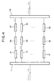
- An optical cross-connector requires the ability to switch signals among different wavelengths, for routing purposes, for example, or to avoid congestion. This capability can be provided by an optical switching apparatus comprising a plurality of wavelength conversion devices 50 as shown in FIG. 4.
- the apparatus in FIG. 4 receives light having a plurality of separate signal wavelengths ⁇ 1 , ⁇ 2 , ..., ⁇ n .
- An optical distributor 11 distributes the received light to a plurality of wavelength selectors 51, which select the individual signal wavelengths ⁇ 1 , ⁇ 2 , ..., ⁇ n , and feed the selected wavelengths to the wavelength conversion devices 50.
- the wavelength conversion devices 50 convert the received signal wavelengths by difference frequency generation.
- Further wavelength selectors 52 select the converted wavelengths, and a multiplexer 12 combines the converted light into a single optical output which again comprises wavelengths ⁇ 1 , ⁇ 2 , ..., ⁇ n .
- the input light and output light signals carry the same signals, but the wavelength assignments of the signals have been rearranged by the wavelength conversion devices 50. For example, the signal carried on wavelength ⁇ 1 in FIG. 4 has been converted to wavelength ⁇ 2 .
- the necessary requirements for the wavelength conversion devices 50 in an optical switch of this type include high conversion efficiency, low noise, and high-speed operation. All of these requirements are met by the present invention.
- the wavelength of converted light output by a particular wavelength conversion device 50 for example, can be switched with substantially no delay by changing the wavelength of the pump light.
- applications of the present invention are not limited to wavelength switching in optical cross-connectors.
- the invented wavelength conversion device achieves high conversion efficiency by the use of Bessel beams, and maximizes the conversion efficiency by having the signal light, pump light, and converted light all polarized parallel to the Z-axis of the anisotropic nonlinear optical crystal.
- a further advantage of the invented wavelength conversion device is that there is no need to form either a waveguide or a periodic domain inversion structure in the anisotropic nonlinear optical crystal. This is an important advantage in relation to manufacturing ease and cost.
- the basic concepts of the present invention namely, all light polarized parallel to the Z-axis of an anisotropic nonlinear optical crystal, use of an axicon lens to create Bessel beams, and phase matching by control of the geometry of the axicon lens, can also be applied to wavelength conversion in an optical parametric oscillator, wavelength conversion by four-wave mixing, and in principle, at least, to wavelength conversion employing third-order and higher-order nonlinear effects.
- These concepts can furthermore be employed in other devices employing nonlinear optics, including optical parametric amplifiers.
Landscapes
- Physics & Mathematics (AREA)
- Nonlinear Science (AREA)
- General Physics & Mathematics (AREA)
- Optics & Photonics (AREA)
- Optical Modulation, Optical Deflection, Nonlinear Optics, Optical Demodulation, Optical Logic Elements (AREA)
- Lasers (AREA)
- Optical Communication System (AREA)
Applications Claiming Priority (3)
| Application Number | Priority Date | Filing Date | Title |
|---|---|---|---|
| JP30456496A JP3272250B2 (ja) | 1996-11-15 | 1996-11-15 | 波長変換装置 |
| JP30456496 | 1996-11-15 | ||
| JP304564/96 | 1996-11-15 |
Publications (3)
| Publication Number | Publication Date |
|---|---|
| EP0843198A2 true EP0843198A2 (fr) | 1998-05-20 |
| EP0843198A3 EP0843198A3 (fr) | 1999-03-17 |
| EP0843198B1 EP0843198B1 (fr) | 2001-07-04 |
Family
ID=17934519
Family Applications (1)
| Application Number | Title | Priority Date | Filing Date |
|---|---|---|---|
| EP97115457A Expired - Lifetime EP0843198B1 (fr) | 1996-11-15 | 1997-09-05 | Dispositif de conversion de longueur d'onde utilisant des faisceaux de Bessel avec polarisation parallèle |
Country Status (4)
| Country | Link |
|---|---|
| US (1) | US5943161A (fr) |
| EP (1) | EP0843198B1 (fr) |
| JP (1) | JP3272250B2 (fr) |
| DE (1) | DE69705482T2 (fr) |
Cited By (1)
| Publication number | Priority date | Publication date | Assignee | Title |
|---|---|---|---|---|
| WO2006059084A1 (fr) * | 2004-11-30 | 2006-06-08 | The University Court Of The University Of St Andrews | Photoporation de cellules |
Families Citing this family (8)
| Publication number | Priority date | Publication date | Assignee | Title |
|---|---|---|---|---|
| US6317252B1 (en) * | 1998-01-06 | 2001-11-13 | California Institute Of Technology | Dynamic channel copying device for use in fiber optics system using a nonlinear optical media |
| JP4517698B2 (ja) * | 2003-09-26 | 2010-08-04 | 三菱電機株式会社 | 波長変換レーザ装置 |
| US7557930B2 (en) * | 2004-11-23 | 2009-07-07 | Lockheed Martin Corporation | Bessel beam interferometer and measurement method |
| WO2006072183A2 (fr) * | 2005-01-10 | 2006-07-13 | Kresimir Franjic | Systeme laser pour la production d'impulsions sous-nanosecondes haute puissance a longueurs d'ondes controlables dans la region 2-15 $g(m)m |
| US8244083B2 (en) * | 2007-09-17 | 2012-08-14 | Seidman Abraham N | Steerable, thin far-field electromagnetic beam |
| US9821522B2 (en) * | 2012-04-16 | 2017-11-21 | Poincare Systems, Inc. | Axicons and methods of making the same |
| US9740081B1 (en) * | 2015-02-20 | 2017-08-22 | Iowa State Research Foundation, Inc. | Double lens device for tunable harmonic generation of laser beams in KBBF/RBBF crystals or other non-linear optic materials |
| CN109346849B (zh) * | 2018-09-06 | 2021-01-08 | 中国科学院国家空间科学中心 | 一种产生毫米波贝塞尔波束的装置 |
Family Cites Families (7)
| Publication number | Priority date | Publication date | Assignee | Title |
|---|---|---|---|---|
| US5355246A (en) * | 1988-10-12 | 1994-10-11 | Fuji Electric Co., Ltd. | Wavelength conversion device |
| JP2837505B2 (ja) * | 1990-05-19 | 1998-12-16 | パイオニア株式会社 | ファイバー型波長変換素子 |
| JPH0475037A (ja) * | 1990-07-17 | 1992-03-10 | Pioneer Electron Corp | ファイバー型波長変換素子 |
| JP2895204B2 (ja) * | 1990-10-22 | 1999-05-24 | パイオニア株式会社 | 光波長変換素子及びその製造方法 |
| JPH04204720A (ja) * | 1990-11-30 | 1992-07-27 | Pioneer Electron Corp | 波長変換素子 |
| US5278930A (en) * | 1991-08-14 | 1994-01-11 | Pioneer Electronic Corporation | Fiber type wavelength converter |
| JP3767927B2 (ja) * | 1995-01-31 | 2006-04-19 | 沖電気工業株式会社 | 波長変換方法及びそれを用いた波長変換装置 |
-
1996
- 1996-11-15 JP JP30456496A patent/JP3272250B2/ja not_active Expired - Fee Related
-
1997
- 1997-09-05 DE DE69705482T patent/DE69705482T2/de not_active Expired - Lifetime
- 1997-09-05 EP EP97115457A patent/EP0843198B1/fr not_active Expired - Lifetime
- 1997-10-06 US US08/944,299 patent/US5943161A/en not_active Expired - Fee Related
Cited By (2)
| Publication number | Priority date | Publication date | Assignee | Title |
|---|---|---|---|---|
| WO2006059084A1 (fr) * | 2004-11-30 | 2006-06-08 | The University Court Of The University Of St Andrews | Photoporation de cellules |
| US8080399B2 (en) | 2004-11-30 | 2011-12-20 | The University of Court of the University of St. Andrews | Photoporation of cells |
Also Published As
| Publication number | Publication date |
|---|---|
| DE69705482T2 (de) | 2002-04-18 |
| JPH10142645A (ja) | 1998-05-29 |
| JP3272250B2 (ja) | 2002-04-08 |
| US5943161A (en) | 1999-08-24 |
| DE69705482D1 (de) | 2001-08-09 |
| EP0843198A3 (fr) | 1999-03-17 |
| EP0843198B1 (fr) | 2001-07-04 |
Similar Documents
| Publication | Publication Date | Title |
|---|---|---|
| Qi et al. | Integrated lithium niobate photonics | |
| Suhara et al. | Waveguide nonlinear-optic devices | |
| Toney | Lithium niobate photonics | |
| Lifante | Integrated photonics: fundamentals | |
| US7489436B1 (en) | Hybrid integrated source of polarization-entangled photons | |
| EP0817988B1 (fr) | Modulateur electro-optique non affecte par la polarisation | |
| US4984861A (en) | Low-loss proton exchanged waveguides for active integrated optic devices and method of making same | |
| US20080075410A1 (en) | Compact, single chip-based, entangled polarization-state photon sources and methods for generating photons in entangled polarization states | |
| Johnstone et al. | Fibre optic modulators using active multimode waveguide overlays | |
| US4856094A (en) | Arrangement for polarization control, such as for an optical heterodyne or homodyne receiver | |
| US5303315A (en) | Near Z digital switch | |
| US4895422A (en) | Phase-matchable, single-mode fiber-optic device | |
| EP0843198B1 (fr) | Dispositif de conversion de longueur d'onde utilisant des faisceaux de Bessel avec polarisation parallèle | |
| US7009759B2 (en) | Multiple channel optical frequency mixers for all-optical signal processing | |
| CN105182654A (zh) | 偏振纠缠光子的三明治波导源 | |
| Johnson | Optical modulators for fiber optic sensors | |
| EP1186942A2 (fr) | Appareil de conversion de longeur d'onde | |
| US5734494A (en) | Wavelength conversion device and wavelength conversion method | |
| US5835644A (en) | TE-pass optical waveguide polarizer using elecro-optic polymers | |
| EP0398271B1 (fr) | Dispositif de conversion de longueur d'onde optique | |
| Sarkar et al. | All-optical method of generation of phase shift keying data using optical pockels crystal | |
| Youngquist et al. | All-fibre components using periodic coupling | |
| Hauden et al. | Quasi-polarization-independent Mach-Zehnder coherence modulator/demodulator integrated in Z-propagating lithium niobate | |
| Porte et al. | Integrated TE-TM mode converter on Y-cut Z-propagating LiNbO/sub 3/with an electrooptic phase matching for coherence multiplexing | |
| Petrov | Acoustooptic and electrooptic guided wave conversion to leaky waves in an anisotropic optical waveguide |
Legal Events
| Date | Code | Title | Description |
|---|---|---|---|
| PUAI | Public reference made under article 153(3) epc to a published international application that has entered the european phase |
Free format text: ORIGINAL CODE: 0009012 |
|
| AK | Designated contracting states |
Kind code of ref document: A2 Designated state(s): DE FR GB |
|
| AX | Request for extension of the european patent |
Free format text: AL;LT;LV;RO;SI |
|
| PUAL | Search report despatched |
Free format text: ORIGINAL CODE: 0009013 |
|
| AK | Designated contracting states |
Kind code of ref document: A3 Designated state(s): AT BE CH DE DK ES FI FR GB GR IE IT LI LU MC NL PT SE |
|
| AX | Request for extension of the european patent |
Free format text: AL;LT;LV;RO;SI |
|
| 17P | Request for examination filed |
Effective date: 19990913 |
|
| AKX | Designation fees paid |
Free format text: DE FR GB |
|
| GRAG | Despatch of communication of intention to grant |
Free format text: ORIGINAL CODE: EPIDOS AGRA |
|
| 17Q | First examination report despatched |
Effective date: 20000906 |
|
| GRAG | Despatch of communication of intention to grant |
Free format text: ORIGINAL CODE: EPIDOS AGRA |
|
| GRAH | Despatch of communication of intention to grant a patent |
Free format text: ORIGINAL CODE: EPIDOS IGRA |
|
| GRAH | Despatch of communication of intention to grant a patent |
Free format text: ORIGINAL CODE: EPIDOS IGRA |
|
| GRAA | (expected) grant |
Free format text: ORIGINAL CODE: 0009210 |
|
| AK | Designated contracting states |
Kind code of ref document: B1 Designated state(s): DE FR GB |
|
| ET | Fr: translation filed | ||
| REF | Corresponds to: |
Ref document number: 69705482 Country of ref document: DE Date of ref document: 20010809 |
|
| REG | Reference to a national code |
Ref country code: GB Ref legal event code: IF02 |
|
| PLBE | No opposition filed within time limit |
Free format text: ORIGINAL CODE: 0009261 |
|
| STAA | Information on the status of an ep patent application or granted ep patent |
Free format text: STATUS: NO OPPOSITION FILED WITHIN TIME LIMIT |
|
| 26N | No opposition filed | ||
| REG | Reference to a national code |
Ref country code: GB Ref legal event code: 732E Free format text: REGISTERED BETWEEN 20090416 AND 20090422 |
|
| REG | Reference to a national code |
Ref country code: FR Ref legal event code: TP |
|
| PGFP | Annual fee paid to national office [announced via postgrant information from national office to epo] |
Ref country code: GB Payment date: 20090902 Year of fee payment: 13 |
|
| PGFP | Annual fee paid to national office [announced via postgrant information from national office to epo] |
Ref country code: DE Payment date: 20090903 Year of fee payment: 13 |
|
| PGFP | Annual fee paid to national office [announced via postgrant information from national office to epo] |
Ref country code: FR Payment date: 20091012 Year of fee payment: 13 |
|
| GBPC | Gb: european patent ceased through non-payment of renewal fee |
Effective date: 20100905 |
|
| REG | Reference to a national code |
Ref country code: FR Ref legal event code: ST Effective date: 20110531 |
|
| REG | Reference to a national code |
Ref country code: DE Ref legal event code: R119 Ref document number: 69705482 Country of ref document: DE Effective date: 20110401 |
|
| PG25 | Lapsed in a contracting state [announced via postgrant information from national office to epo] |
Ref country code: DE Free format text: LAPSE BECAUSE OF NON-PAYMENT OF DUE FEES Effective date: 20110401 Ref country code: FR Free format text: LAPSE BECAUSE OF NON-PAYMENT OF DUE FEES Effective date: 20100930 |
|
| PG25 | Lapsed in a contracting state [announced via postgrant information from national office to epo] |
Ref country code: GB Free format text: LAPSE BECAUSE OF NON-PAYMENT OF DUE FEES Effective date: 20100905 |