EP0843206A1 - Système de sécurité - Google Patents
Système de sécurité Download PDFInfo
- Publication number
- EP0843206A1 EP0843206A1 EP97420208A EP97420208A EP0843206A1 EP 0843206 A1 EP0843206 A1 EP 0843206A1 EP 97420208 A EP97420208 A EP 97420208A EP 97420208 A EP97420208 A EP 97420208A EP 0843206 A1 EP0843206 A1 EP 0843206A1
- Authority
- EP
- European Patent Office
- Prior art keywords
- spindle
- slide
- safety system
- door
- rest
- Prior art date
- Legal status (The legal status is an assumption and is not a legal conclusion. Google has not performed a legal analysis and makes no representation as to the accuracy of the status listed.)
- Granted
Links
- 230000005484 gravity Effects 0.000 claims description 2
- 238000004519 manufacturing process Methods 0.000 abstract description 2
- 230000000295 complement effect Effects 0.000 description 3
- 230000000284 resting effect Effects 0.000 description 3
- 238000004806 packaging method and process Methods 0.000 description 2
- 241000237509 Patinopecten sp. Species 0.000 description 1
- 230000001133 acceleration Effects 0.000 description 1
- 230000002950 deficient Effects 0.000 description 1
- 238000000605 extraction Methods 0.000 description 1
- 238000012986 modification Methods 0.000 description 1
- 230000004048 modification Effects 0.000 description 1
- 235000020637 scallop Nutrition 0.000 description 1
Images



Classifications
-
- B—PERFORMING OPERATIONS; TRANSPORTING
- B65—CONVEYING; PACKING; STORING; HANDLING THIN OR FILAMENTARY MATERIAL
- B65H—HANDLING THIN OR FILAMENTARY MATERIAL, e.g. SHEETS, WEBS, CABLES
- B65H75/00—Storing webs, tapes, or filamentary material, e.g. on reels
- B65H75/02—Cores, formers, supports, or holders for coiled, wound, or folded material, e.g. reels, spindles, bobbins, cop tubes, cans, mandrels or chucks
- B65H75/18—Constructional details
- B65H75/24—Constructional details adjustable in configuration, e.g. expansible
- B65H75/242—Expansible spindles, mandrels or chucks, e.g. for securing or releasing cores, holders or packages
-
- B—PERFORMING OPERATIONS; TRANSPORTING
- B65—CONVEYING; PACKING; STORING; HANDLING THIN OR FILAMENTARY MATERIAL
- B65H—HANDLING THIN OR FILAMENTARY MATERIAL, e.g. SHEETS, WEBS, CABLES
- B65H75/00—Storing webs, tapes, or filamentary material, e.g. on reels
- B65H75/02—Cores, formers, supports, or holders for coiled, wound, or folded material, e.g. reels, spindles, bobbins, cop tubes, cans, mandrels or chucks
- B65H75/18—Constructional details
- B65H75/22—Constructional details collapsible; with removable parts
- B65H75/2245—Constructional details collapsible; with removable parts connecting flange to hub
-
- G—PHYSICS
- G03—PHOTOGRAPHY; CINEMATOGRAPHY; ANALOGOUS TECHNIQUES USING WAVES OTHER THAN OPTICAL WAVES; ELECTROGRAPHY; HOLOGRAPHY
- G03B—APPARATUS OR ARRANGEMENTS FOR TAKING PHOTOGRAPHS OR FOR PROJECTING OR VIEWING THEM; APPARATUS OR ARRANGEMENTS EMPLOYING ANALOGOUS TECHNIQUES USING WAVES OTHER THAN OPTICAL WAVES; ACCESSORIES THEREFOR
- G03B27/00—Photographic printing apparatus
- G03B27/32—Projection printing apparatus, e.g. enlarger, copying camera
- G03B27/52—Details
- G03B27/58—Baseboards, masking frames, or other holders for the sensitive material
- G03B27/587—Handling photosensitive webs
- G03B27/588—Supply rolls; Cutting arrangements
Definitions
- the present invention relates to the packaging of photographic products and more particularly to the packaging of products in strip form wound on cores; these strips being very long.
- the invention is therefore particularly useful for packages in the form of containers comprising essentially a base adapted to handling by lift truck, a light-tight enclosure provided with a door and a cantilever spindle situated inside the enclosure and designed to receive the rolls.
- the invention aims to develop a safety system in which the container can be closed only when the rolls can no longer come into abutment against the door.
- the patent FR-A-2 658 156 describes a package comprising a light-tight enclosure supported by a base of the pallet type in order to be able to be moved by a lift truck.
- This package comprises at least one cantilever spindle onto which the rolls to be supplied are introduced.
- a locking device immobilises the strips during their transportation. In the embodiment depicted this locking is obtained by expansion of the diameter of the spindle. No system is provided to prevent the closure of the doors as long as the rollers are not immobilised on the spindle.
- the patent FR-A-2 663 007 describes a package comprising essentially a base adapted to handling by lift truck, a light-tight enclosure and a cantilever spindle designed to receive rolls of products in strip form.
- the package is closed by an end cover which can be fixed to the spindle.
- the spindle is provided with immobilisation devices associated with each of the rolls by increasing the diameter of the spindle, these devices being controlled from outside.
- immobilisation devices associated with each of the rolls by increasing the diameter of the spindle, these devices being controlled from outside.
- Such a device enables the door to be reclosed without there being any need to lock the rolls since this operation can be performed once the container is closed.
- this arrangement may prove defective since the door can be closed without the operation of locking the rolls having been performed and the operator may forget to perform this operation.
- this locking operation since this locking operation is controlled from outside, it may happen that locking has indeed been effected but that subsequently an unlocking operation has taken place.
- the patent FR-A-2 731 527 describes a package of the same type as those described previously, having means internal to the container for driving the rolls towards the outside of the container. None is mentioned with regard to the locking of the rolls.
- the packages described above therefore have no reliable device aimed at preventing their movement as long as the rolls disposed on the spindle are not held on this spindle.
- the object of the invention is therefore to provide a package which does not have the above-mentioned drawbacks.
- the aim of the invention is to provide a safety system aimed at preventing the closure of the container as long as the retaining operation has not been performed.
- the invention aims to provide a simple and effective system for immobilising the rolls.
- the invention also makes it possible to lock the spools even when the door is not closed; this enables the container to be moved without risk of causing the rolls to fall.
- a safety system for a container for products in strip form wound on cores which container comprises on the one hand a spindle mounted practically horizontally in cantilever and designed to support the cores and on the other hand a door which can be located on the spindle by a locating device.
- the system is characterised in that it comprises, at the free end of the spindle, an element able to move between a first resting position in which on the one hand this element does not project beyond the volume delimited by the cylinder generated by the internal diameter of the cores and on the other hand this element prevents the closure of the door, and a second resting position in which on the one hand this element projects beyond the volume delimited by the cylinder generated by the internal diameter of the cores in order to prevent the cores from leaving the spindle and on the other hand this element releases the locating device so as to allow the closure of the door.
- the safety system comprises a) an elongate hollow housing situated at the free end of the spindle and opening out on at least part of the periphery of the spindle, b) an element, the overall shape of which is a rectangular parallelpiped, able to be contained at least partially in the volume delimited by the hollow housing and c) a means of attaching the element to the spindle allowing a movement of the element in the longitudinal direction of the housing.
- the element is attached to the spindle by means of a pin disposed transversely to the housing and entering an oblong opening in the element.
- the element is provided at one of its ends with a circular surface centred on the end of the oblong opening which is closest so as to allow the tilting of this element in a plane perpendicular to the pin.
- the element is a slide attached to the spindle by means of two pins fixed to the spindle and disposed in an oblong opening in the slide, the length of the opening being greater than the distance between the two pins.
- a holding system comprising a stud forced in a given direction immobilises the spindle and slide in one or other of the resting positions and one with respect to the other.
- the invention is particularly useful in the transportation of photosensitive material with which it is very important that no light reaches the photosensitive product during transportation. It is more and more usual to transport rolls of photosensitive products of great length. These rolls, the length of which may be as great as 2000 m, each weigh around 50 kg. They are generally transported by means of containers such as the ones described for example in the patents FR-A-2 658 156, FR-A-2 663 007 and FR-A-2 731 527.
- the rolls When they are transported by lorry the rolls can be subjected to significant accelerations which, because of their inertia, can cause them to move along the spindle and, in the absence of any system of immobilising the rolls, the forces exerted on the door can deform it and even open it, irremediably damaging the photosensitive product.
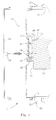
- Figure 1 depicts highly diagrammatically the door 10 of a container 1 and one of the ends 11 of this container 1.
- the container has been depicted in this figure only by two of its lateral walls 12, 13 and by a spindle 30 which it contains.
- the spindle 30 disposed cantilevered inside the container is practically horizontal.
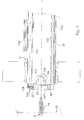
- This spindle receives rolls 5 of products in strip form (only one of which has been shown diagrammatically in Figure 7).
- the container is provided with a system of locking the door 10, which, in the embodiment depicted in Figures 1 and 2, can adopt the form of a lever bolt 90 coming into engagement with a complementary part of the door.
- the end of the spindle is provided with an element or slide 20 attached to the spindle.
- the slide is housed at least partially in a groove 31 or elongate hollow housing.
- the slide 20 is connected to the spindle 30 by means of two pins 32 disposed transversely to the groove 31 and passing through an oblong opening 21 made in the slide.
- the length of the oblong opening 21 is greater than the distance between the pins 32. In this way the slide is able to move in the groove parallel to the length of the hollow housing.
- the slide 20 can be connected to the spindle by any other suitable means.
- the slide can be provided with two lateral flanges 22 entering channels 33 in the spindle.
- the slide can have a trapezoidal cross section, the large base of which is in contact with the spindle; the groove 31 itself also having a complementary trapezoidal shape.
- the slide 20 can be disposed in two different positions of rest depicted respectively in Figures 1 and 2.
- a holding means comprising a stud 40, forced in a given direction by a spring 41, enters a cavity, for example a V-shaped recess 23.
- the spring is disposed in a niche 34 in the spindle so as to force the stud 40 towards the slide 20.
- the niche 34 could be formed in the slide 20.
- the stud 40 would be forced towards the spindle 30, the V-shaped recess being formed in the spindle.
- the slide 20 In its first position of rest, depicted in Figure 1, the slide 20 projects sufficiently beyond the volume delimited by the internal diameter of the cores on which the strips of photosensitive product are wound. In this way the rolls are not able to leave the spindle 30.
- the slide 20 also comprises a cavity 24, the shape of which is complementary to a projecting part 14 carried by the door. As can be seen in broken lines in Figure 1, when the slide 20 is in its first position of rest, the position of the cavity carried by the slide is such that the projecting part 14 of the door 10 enters the cavity 24 in order to be able to close the door. The cooperation between the cavity 24 and the projecting part 14 forms a locating device.
- each of the positions of rest can be defined by a V-shaped recess.
- the groove 31 has a practically vertical orientation and one of the positions of rest, the one in which the slide does not project beyond the volume delimited by the internal diameter of the cores, is defined by the lower position of the slide, that is to say the one in which the top part of the oblong opening comes into abutment on the top pin 32, which provides a stable position of rest. Under these conditions a single groove is necessary to provide stability for the other position of rest.
- the first position of rest the one in which the slide projects beyond the volume delimited by the internal diameter of the cores, by the cooperation of the top part of the oblong opening with the top pin.
- the V-shaped recess serving to define the position in which the slide does not project beyond the volume delimited by the internal diameter of the cores. This position makes it possible to lock the rolls on the spindle even in the event of breakage of the spring 42.
- the spindle 30 is similar to the one used in the document FR-A-2 731 527. It is composed of a hollow tube 130 at the end of which a piece 131 has been screwed. The spindle is provided at its periphery with three sliding strips 132 made of suitable material. The strips 132 provide a flexible sliding support for the cores on which the photosensitive product is wound.
- the container is provided with an extraction device 133 for causing the cores situated on the spindle to leave the container.
- This device comprises an endless screw 133 giving rise, through its rotation, to the movement of a pusher 134 along the spindle 30.
- One of the ends of the endless screw 133 enters a bearing 135 fixed to the piece 131.
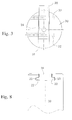
- the end of the spindle is provided with an element 20 attached to the spindle.
- the element is housed at least partially in a groove 31 or elongate hollow housing.
- the element 20 is connected to the spindle 30 by means of a pin 32 disposed transversely to the groove 31 and passing through an oblong opening 21 formed in this element. In this way this element is able to move in the groove 31 parallel to the length of the hollow housing.
- the element 20 can be disposed in two different positions of rest depicted respectively in Figures 4 and 5.
- the groove 31 is oriented in a substantially vertical direction so that the restoring force which has to be applied to the element 20 in order to maintain it in one or other of its positions of rest is produced by the force of gravity.
- the element 20 has at one of its ends a cylindrical surface 126 centred on the closer of the ends of the oblong opening 21 so as to be able to cause the element 20 to rotate in a plane perpendicular to the axis 32 which connects it to the piece 131.
- the pin 32 connecting the element to the spindle 30 is situated at the one of the ends of the oblong opening 21 which is not concentric with the circular surface 126.
- the element 20 forced downwards by its weight is not able to rotate about the pin 32 since it is locked by the base of the groove 31 and is therefore immobilised.
- the element 20 projects sufficiently beyond the volume delimited by the internal diameter of the cores on which the strips of photosensitive product are wound, so that the rolls are not able to leave the spindle 30.
- the piece 131 is provided either with a cavity 24 or with a hole provided with a thread 136, or both.
- the door 20 either has a projecting part 14, similar to that depicted in Figure 1, the shape of which is able to enter the cavity 24, or is locked by means of a screw 8 which is able to come into engagement with the thread 136 when the door is closed.
- the element 20 has a shape arranged so as to prevent the projecting part 14 of the door from cooperating with the cavity 24 of the piece 131 or the screw 8 from being introduced into the thread 136, when this element occupies its second position of rest depicted in Figure 5. It is clear that the shape of the element must be adapted to the particular conditions of manufacture of the spindle or mounting thereof.
- the loading stresses due to the weight of the rolls and to the conditions of transportation of the containers give rise to stresses in the dimensions of the element 20. Because of this, it may be necessary to provide, on the element, a scalloping 121 or cutout whose shape allows cooperation between the projecting part and the cavity or between the screw and the threaded hole when the element is in its first position of rest and prevents such cooperation when the element is in its second position of rest.
- the element 20 when it is desired to transport the rolls 5 with a minimum of risk, the element 20 is disposed in its first position so as to prevent the rolls from leaving the spindle 30. Then the pusher 134 is moved towards the free end of the spindle. This causes the rolls 5 to be put in abutment with each other and to be clamped between the pusher 134 and element 20.
Landscapes
- Physics & Mathematics (AREA)
- General Physics & Mathematics (AREA)
- Packaging Of Machine Parts And Wound Products (AREA)
- Details Of Rigid Or Semi-Rigid Containers (AREA)
- Storage Of Web-Like Or Filamentary Materials (AREA)
Applications Claiming Priority (2)
| Application Number | Priority Date | Filing Date | Title |
|---|---|---|---|
| FR9614179 | 1996-11-15 | ||
| FR9614179A FR2755953B1 (fr) | 1996-11-15 | 1996-11-15 | Systeme de securite |
Publications (2)
| Publication Number | Publication Date |
|---|---|
| EP0843206A1 true EP0843206A1 (fr) | 1998-05-20 |
| EP0843206B1 EP0843206B1 (fr) | 2004-01-21 |
Family
ID=9497833
Family Applications (1)
| Application Number | Title | Priority Date | Filing Date |
|---|---|---|---|
| EP97420208A Expired - Lifetime EP0843206B1 (fr) | 1996-11-15 | 1997-11-07 | Système de sécurité |
Country Status (4)
| Country | Link |
|---|---|
| US (1) | US5960955A (fr) |
| EP (1) | EP0843206B1 (fr) |
| DE (1) | DE69727282T2 (fr) |
| FR (1) | FR2755953B1 (fr) |
Families Citing this family (1)
| Publication number | Priority date | Publication date | Assignee | Title |
|---|---|---|---|---|
| US10362899B2 (en) | 2015-03-13 | 2019-07-30 | Adrenaline Barbecue Company, LLC | Barbecue grill accessory and method for preparing food |
Citations (5)
| Publication number | Priority date | Publication date | Assignee | Title |
|---|---|---|---|---|
| DE4011959A1 (de) * | 1990-04-12 | 1991-10-17 | Badische Stahlwerke | Spule zum aufwickeln von draht, metallblech o. dgl. |
| FR2691448A1 (fr) * | 1992-05-21 | 1993-11-26 | Filthaut Fa Franz | Bobine en matière synthétique pour l'enroulement de produits enroulables en forme de bande ou de fil. |
| EP0572338A1 (fr) * | 1992-05-29 | 1993-12-01 | Eastman Kodak Company | Cassette et mécanisme anti-effet ressort de montre pour rouleau de bande |
| US5287964A (en) * | 1990-02-12 | 1994-02-22 | Eastman Kodak Company | Packing process, packing for photographic web materials |
| US5409179A (en) * | 1993-07-07 | 1995-04-25 | Recherche Et Developpement (Jl) Inc. | Collapsible reel |
Family Cites Families (6)
| Publication number | Priority date | Publication date | Assignee | Title |
|---|---|---|---|---|
| US1288401A (en) * | 1917-09-08 | 1918-12-17 | Duplicator Mfg Company | Package. |
| US4903833A (en) * | 1988-10-17 | 1990-02-27 | The Mead Corporation | Cartridge for web-type media material |
| FR2663007A1 (fr) * | 1990-06-08 | 1991-12-13 | Kodak Pathe | Emballage de produits photographiques en bandes. |
| US5165542A (en) * | 1991-05-07 | 1992-11-24 | Minnesota Mining And Manufacturing Company | Reusable container for tape pancakes |
| US5542534A (en) * | 1994-12-15 | 1996-08-06 | Hoechst Aktiengesellschaft | Packaging system for receiving a film web wound up in roll form onto a winding sleeve |
| FR2731527B1 (fr) * | 1995-03-06 | 1997-05-09 | Kodak Pathe | Container pour produit photosensible en bande |
-
1996
- 1996-11-15 FR FR9614179A patent/FR2755953B1/fr not_active Expired - Fee Related
-
1997
- 1997-08-27 US US08/920,546 patent/US5960955A/en not_active Expired - Fee Related
- 1997-11-07 EP EP97420208A patent/EP0843206B1/fr not_active Expired - Lifetime
- 1997-11-07 DE DE69727282T patent/DE69727282T2/de not_active Expired - Fee Related
Patent Citations (5)
| Publication number | Priority date | Publication date | Assignee | Title |
|---|---|---|---|---|
| US5287964A (en) * | 1990-02-12 | 1994-02-22 | Eastman Kodak Company | Packing process, packing for photographic web materials |
| DE4011959A1 (de) * | 1990-04-12 | 1991-10-17 | Badische Stahlwerke | Spule zum aufwickeln von draht, metallblech o. dgl. |
| FR2691448A1 (fr) * | 1992-05-21 | 1993-11-26 | Filthaut Fa Franz | Bobine en matière synthétique pour l'enroulement de produits enroulables en forme de bande ou de fil. |
| EP0572338A1 (fr) * | 1992-05-29 | 1993-12-01 | Eastman Kodak Company | Cassette et mécanisme anti-effet ressort de montre pour rouleau de bande |
| US5409179A (en) * | 1993-07-07 | 1995-04-25 | Recherche Et Developpement (Jl) Inc. | Collapsible reel |
Also Published As
| Publication number | Publication date |
|---|---|
| DE69727282D1 (de) | 2004-02-26 |
| DE69727282T2 (de) | 2004-11-25 |
| FR2755953B1 (fr) | 1999-02-05 |
| FR2755953A1 (fr) | 1998-05-22 |
| US5960955A (en) | 1999-10-05 |
| EP0843206B1 (fr) | 2004-01-21 |
Similar Documents
| Publication | Publication Date | Title |
|---|---|---|
| US5960960A (en) | Wafer carrier | |
| JP3629658B2 (ja) | トレーラー用自動コンテナ固定装置 | |
| US4846345A (en) | Cassette storing a plurality of electronic component chips including means for securing the cassette to a hopper | |
| US5184743A (en) | Container for housing coil | |
| KR940013546A (ko) | 안과용 렌즈용기의 수납 이송 및 검사장치 | |
| EP0843206B1 (fr) | Système de sécurité | |
| US7562775B2 (en) | Packaging for large anti-friction bearings | |
| US6195961B1 (en) | Stretch film roll mounting frame | |
| JPH05505035A (ja) | 包装方法、写真用ウエブ材料用の包装物 | |
| JPH01275881A (ja) | 容器を保管し、差し入れかつ差し出すための装置 | |
| US7690506B2 (en) | Aircraft brake assembly container and method of using same | |
| JP3968142B2 (ja) | 包装容器における半導体ウェハの支持溝構造 | |
| US20250273495A1 (en) | Industrial Magazine Rack | |
| EP0731376B1 (fr) | Récipient pour un produit photosensible sous forme de bande | |
| US4922353A (en) | Apparatus for loading a tape cartridge for a magnetic instrument | |
| JP4591335B2 (ja) | ストッカー内の棚における基板収納用容器の変位防止装置 | |
| US20090172961A1 (en) | Device To Monitor the Position of an Assembly Containing Nuclear Fuel In a Storage Basket Housing | |
| KR20010048408A (ko) | 와이어 권취 보빈 포장박스 | |
| FI72692C (fi) | Transportanordning. | |
| US5131538A (en) | Fiber optic coil shipping and storage container | |
| EP0567917A1 (fr) | Dispositif de manutention de charges associé à un système d'équilibrage | |
| JPS63187244A (ja) | マスク収納ケ−ス | |
| EP0190800B1 (fr) | Dispositifs pour distribuer des leurres | |
| SU1027091A1 (ru) | Контейнер дл транспортировани сыпучих грузов | |
| JPH0449074Y2 (fr) |
Legal Events
| Date | Code | Title | Description |
|---|---|---|---|
| PUAI | Public reference made under article 153(3) epc to a published international application that has entered the european phase |
Free format text: ORIGINAL CODE: 0009012 |
|
| AK | Designated contracting states |
Kind code of ref document: A1 Designated state(s): DE FR GB NL |
|
| 17P | Request for examination filed |
Effective date: 19981109 |
|
| AKX | Designation fees paid |
Free format text: DE FR GB NL |
|
| RBV | Designated contracting states (corrected) |
Designated state(s): DE FR GB NL |
|
| GRAH | Despatch of communication of intention to grant a patent |
Free format text: ORIGINAL CODE: EPIDOS IGRA |
|
| GRAS | Grant fee paid |
Free format text: ORIGINAL CODE: EPIDOSNIGR3 |
|
| GRAA | (expected) grant |
Free format text: ORIGINAL CODE: 0009210 |
|
| AK | Designated contracting states |
Kind code of ref document: B1 Designated state(s): DE FR GB NL |
|
| REG | Reference to a national code |
Ref country code: GB Ref legal event code: FG4D |
|
| REF | Corresponds to: |
Ref document number: 69727282 Country of ref document: DE Date of ref document: 20040226 Kind code of ref document: P |
|
| PGFP | Annual fee paid to national office [announced via postgrant information from national office to epo] |
Ref country code: GB Payment date: 20041004 Year of fee payment: 8 |
|
| PGFP | Annual fee paid to national office [announced via postgrant information from national office to epo] |
Ref country code: NL Payment date: 20041006 Year of fee payment: 8 |
|
| ET | Fr: translation filed | ||
| PLBE | No opposition filed within time limit |
Free format text: ORIGINAL CODE: 0009261 |
|
| STAA | Information on the status of an ep patent application or granted ep patent |
Free format text: STATUS: NO OPPOSITION FILED WITHIN TIME LIMIT |
|
| 26N | No opposition filed |
Effective date: 20041022 |
|
| PG25 | Lapsed in a contracting state [announced via postgrant information from national office to epo] |
Ref country code: DE Free format text: LAPSE BECAUSE OF NON-PAYMENT OF DUE FEES Effective date: 20050601 |
|
| PG25 | Lapsed in a contracting state [announced via postgrant information from national office to epo] |
Ref country code: FR Free format text: LAPSE BECAUSE OF NON-PAYMENT OF DUE FEES Effective date: 20050729 |
|
| REG | Reference to a national code |
Ref country code: FR Ref legal event code: ST |
|
| PG25 | Lapsed in a contracting state [announced via postgrant information from national office to epo] |
Ref country code: GB Free format text: LAPSE BECAUSE OF NON-PAYMENT OF DUE FEES Effective date: 20051107 |
|
| PG25 | Lapsed in a contracting state [announced via postgrant information from national office to epo] |
Ref country code: NL Free format text: LAPSE BECAUSE OF NON-PAYMENT OF DUE FEES Effective date: 20060601 |
|
| GBPC | Gb: european patent ceased through non-payment of renewal fee |
Effective date: 20051107 |
|
| NLV4 | Nl: lapsed or anulled due to non-payment of the annual fee |
Effective date: 20060601 |