EP0843233A2 - Tonerzuführkartusche - Google Patents
Tonerzuführkartusche Download PDFInfo
- Publication number
- EP0843233A2 EP0843233A2 EP97307888A EP97307888A EP0843233A2 EP 0843233 A2 EP0843233 A2 EP 0843233A2 EP 97307888 A EP97307888 A EP 97307888A EP 97307888 A EP97307888 A EP 97307888A EP 0843233 A2 EP0843233 A2 EP 0843233A2
- Authority
- EP
- European Patent Office
- Prior art keywords
- shutter
- toner
- claw
- toner supply
- supply cartridge
- Prior art date
- Legal status (The legal status is an assumption and is not a legal conclusion. Google has not performed a legal analysis and makes no representation as to the accuracy of the status listed.)
- Granted
Links
Images


Classifications
-
- G—PHYSICS
- G03—PHOTOGRAPHY; CINEMATOGRAPHY; ANALOGOUS TECHNIQUES USING WAVES OTHER THAN OPTICAL WAVES; ELECTROGRAPHY; HOLOGRAPHY
- G03G—ELECTROGRAPHY; ELECTROPHOTOGRAPHY; MAGNETOGRAPHY
- G03G9/00—Developers
-
- G—PHYSICS
- G03—PHOTOGRAPHY; CINEMATOGRAPHY; ANALOGOUS TECHNIQUES USING WAVES OTHER THAN OPTICAL WAVES; ELECTROGRAPHY; HOLOGRAPHY
- G03G—ELECTROGRAPHY; ELECTROPHOTOGRAPHY; MAGNETOGRAPHY
- G03G15/00—Apparatus for electrographic processes using a charge pattern
- G03G15/06—Apparatus for electrographic processes using a charge pattern for developing
- G03G15/08—Apparatus for electrographic processes using a charge pattern for developing using a solid developer, e.g. powder developer
- G03G15/0822—Arrangements for preparing, mixing, supplying or dispensing developer
- G03G15/0877—Arrangements for metering and dispensing developer from a developer cartridge into the development unit
- G03G15/0881—Sealing of developer cartridges
- G03G15/0886—Sealing of developer cartridges by mechanical means, e.g. shutter, plug
-
- G—PHYSICS
- G03—PHOTOGRAPHY; CINEMATOGRAPHY; ANALOGOUS TECHNIQUES USING WAVES OTHER THAN OPTICAL WAVES; ELECTROGRAPHY; HOLOGRAPHY
- G03G—ELECTROGRAPHY; ELECTROPHOTOGRAPHY; MAGNETOGRAPHY
- G03G15/00—Apparatus for electrographic processes using a charge pattern
- G03G15/06—Apparatus for electrographic processes using a charge pattern for developing
- G03G15/08—Apparatus for electrographic processes using a charge pattern for developing using a solid developer, e.g. powder developer
- G03G15/0822—Arrangements for preparing, mixing, supplying or dispensing developer
- G03G15/0848—Arrangements for testing or measuring developer properties or quality, e.g. charge, size, flowability
- G03G15/0849—Detection or control means for the developer concentration
- G03G15/0855—Detection or control means for the developer concentration the concentration being measured by optical means
-
- G—PHYSICS
- G03—PHOTOGRAPHY; CINEMATOGRAPHY; ANALOGOUS TECHNIQUES USING WAVES OTHER THAN OPTICAL WAVES; ELECTROGRAPHY; HOLOGRAPHY
- G03G—ELECTROGRAPHY; ELECTROPHOTOGRAPHY; MAGNETOGRAPHY
- G03G15/00—Apparatus for electrographic processes using a charge pattern
- G03G15/06—Apparatus for electrographic processes using a charge pattern for developing
- G03G15/08—Apparatus for electrographic processes using a charge pattern for developing using a solid developer, e.g. powder developer
- G03G15/0822—Arrangements for preparing, mixing, supplying or dispensing developer
- G03G15/0865—Arrangements for supplying new developer
- G03G15/0875—Arrangements for supplying new developer cartridges having a box like shape
-
- G—PHYSICS
- G03—PHOTOGRAPHY; CINEMATOGRAPHY; ANALOGOUS TECHNIQUES USING WAVES OTHER THAN OPTICAL WAVES; ELECTROGRAPHY; HOLOGRAPHY
- G03G—ELECTROGRAPHY; ELECTROPHOTOGRAPHY; MAGNETOGRAPHY
- G03G2215/00—Apparatus for electrophotographic processes
- G03G2215/06—Developing structures, details
- G03G2215/066—Toner cartridge or other attachable and detachable container for supplying developer material to replace the used material
- G03G2215/068—Toner cartridge or other attachable and detachable container for supplying developer material to replace the used material having a box like shape
-
- Y—GENERAL TAGGING OF NEW TECHNOLOGICAL DEVELOPMENTS; GENERAL TAGGING OF CROSS-SECTIONAL TECHNOLOGIES SPANNING OVER SEVERAL SECTIONS OF THE IPC; TECHNICAL SUBJECTS COVERED BY FORMER USPC CROSS-REFERENCE ART COLLECTIONS [XRACs] AND DIGESTS
- Y10—TECHNICAL SUBJECTS COVERED BY FORMER USPC
- Y10S—TECHNICAL SUBJECTS COVERED BY FORMER USPC CROSS-REFERENCE ART COLLECTIONS [XRACs] AND DIGESTS
- Y10S222/00—Dispensing
- Y10S222/01—Xerography
Definitions
- the present invention relates to a toner supply cartridge for use in an image forming apparatus such as a copying machine, a facsimile machine or a printer.
- a toner supply cartridge typically includes a cartridge body which contains toner therein and has a toner fall aperture formed in the bottom face thereof.
- the toner fall aperture is closed with a slidable shutter.
- the toner supply cartridge is replaced when little toner remains in a hopper provided in a developer unit of an image forming apparatus.
- the shutter closing the toner fall aperture of the cartridge is slid so that the toner fall aperture is opened.
- toner inside the cartridge body falls into the hopper from the toner fall aperture thereby to be supplied into the developer unit.
- the replacement of the toner supply cartridge requires a two-step procedure including the steps of: removing the used toner supply cartridge from the image forming apparatus and then setting a new toner supply cartridge in the image forming apparatus; and sliding the shutter of the new toner supply cartridge.
- This procedure for the replacement of the toner supply cartridge is troublesome for a user unfamiliar with the cartridge replacement.
- a toner supply cartridge for use in an image forming apparatus such as a copying machine, a facsimile machine or a printer, which comprises a cartridge body containing toner therein and having a toner fall aperture formed in an under face thereof, a shutter provided in association with the toner fall aperture and adapted to be slidably shifted between a closed position where the toner fall aperture is closed and an open position where the toner fall aperture is opened, and a claw provided on the shutter, the claw being in a first, unlockable state when the shutter is located in the closed position and in a second, lockable state when the shutter is located in the open position.
- a flange is provided around the toner fall aperture so as to project laterally therefrom, and the shutter is adapted to slide with respect to the flange.
- the flange can be formed with a cut-away portion, and one part of the claw is fitted in the cut-away portion and another part of the claw is in the unlockable state when the shutter is located in the closed position.
- the one part of the claw is guided away from the cut-away portion to a side face of the flange and the other part of the claw is in the lockable state when the shutter is located in the open position.
- the claw is formed of a resin integrally with the shutter.
- the image forming apparatus preferably comprises a guide for guiding the cartridge body, the guide having a shutter shift prohibiting portion which, when the cartridge body is inserted into the image forming apparatus to be set in a predetermined position, prohibits the shutter from being shifted but permits the cartridge body to be moved, allowing the shutter to be shifted from the closed position to the open position.
- the guide can include a return portion for returning the shutter from the open position to the closed position with the claw in the lockable state being kept locked when the cartridge body is withdrawn from the image forming apparatus.
- an image forming apparatus such as a copying machine, a facsimile machine or a printer, in conjunction with a replaceable toner supply cartridge adapted to be selectively fitted to the image forming apparatus for supplying toner thereto, the toner supply cartridge comprising:
- the shutter is automatically shifted to the open position simply by inserting the toner supply cartridge along the guide in a predetermined insertion direction. Therefore, even a user unfamiliar with the cartridge replacement can readily set the toner supply cartridge without any trouble.
- the shutter When the toner supply cartridge is to be removed, the shutter is automatically shifted to the closed position simply by withdrawing the toner supply cartridge in a direction opposite to the insertion direction. Therefore, the user does not have to intentionally close the toner fall aperture by sliding the shutter, nor fails to close the toner fall aperture.
- Fig. 1 is a sectional view schematically illustrating the internal construction of a copying machine in which a toner supply cartridge according to one embodiment of the present invention is set.
- Fig. 2 is a perspective view illustrating the-copying machine in a state where the toner supply cartridge is to be inserted therein or removed therefrom.
- this embodiment is directed to a case where the toner supply cartridge is set in the copying machine, the toner supply cartridge can be applied not only to a copying machine but also to any other image forming apparatuses such as a facsimile machine and a printer.
- the copying machine includes an optical system 12 for illuminating a document original for scanning thereof, an image formation system 13 for forming a toner image on a sheet, and a sheet transportation system 14 for conveying a sheet from a sheet tray 22 to a sheet discharge tray 24 through the image formation system 13 and a fixing unit 23, which are all provided in a copying machine body 11 thereof.
- a transparent document original placing plate 15 on which a document original (not shown) is placed is fitted on a top face of the copying machine body 11, and a document original cover 16 for pressing the document original against the document original placing plate 15 is provided above the document original placing plate 15.
- the optical system 12 is provided below the document original placing plate 15.
- the image formation system 13 is disposed below the optical system 12, and has a photoreceptor drum 17.
- a main charger 18, a developer unit 19, a transfer charger 20 and a cleaning unit 21 are provided around the photoreceptor 17 in this order along the direction of rotation of the photoreceptor 17.
- the photoreceptor 17 is driven for rotation in synchronization with the scanning of the document original by the optical system 12 and, after being uniformly charged by the main charger 18, is exposed to illumination from the optical system 12.
- an electrostatic latent image is formed on the surface of the photoreceptor 17.
- the electrostatic latent image is developed into a toner image by the developer unit 19.
- the toner image is transferred onto a sheet (not shown) supplied from the sheet tray 22.
- the transferred toner image is thermally fixed on the sheet by the fixing unit 23.
- the sheet carrying the toner image fixed thereon is discharged into the discharge tray 24. Toner remaining on the surface of the photoreceptor 17 after the image transfer is recovered by the cleaning unit 21.
- a toner supply cartridge 32 for supplying toner to a hopper 31 in the developer unit 19 is set in the copying machine body 11, and a guide 33 is provided, for example, on an upper face of the hopper 31 for guiding the toner supply cartridge 32 for insertion and withdrawal thereof.
- a guide 33 is provided, for example, on an upper face of the hopper 31 for guiding the toner supply cartridge 32 for insertion and withdrawal thereof.
- an openable cover 26 constituting part of a front face 25 of the copying machine body 11 is opened and the used toner supply cartridge is withdrawn from the copying machine body 11 for replacement of the toner supply cartridge 32.
- the new toner supply cartridge 32 is guided by the guide 33 to be inserted into the copying machine body 11.
- the openable cover 26 is lifted up and closed. Thus, the replacement of the toner supply cartridge 32 is completed.
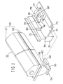
- Fig. 3 is a perspective view illustrating the construction of the toner supply cartridge 32 and the construction of the guide 33.
- Fig. 4 is a sectional view taken along a line perpendicular to the length of the toner supply cartridge 32.
- the toner supply cartridge 32 has an elongate cartridge body 53 including an upper case 51 and a lower case 52, and the cartridge body 53 contains therein toner to be supplied.
- the cartridge body 53 has a connector portion 54 provided in an under-face thereof adjacent to one end thereof and formed with a toner fall aperture 56 communicating between the inside and outside of the cartridge body 53. It is noted that the cartridge body 53 may be constructed such that the upper case 51 and the lower case 52 are integrally formed.
- a flange 55 projecting horizontally from the periphery of the connector portion 54.
- a shutter 60 for slidably opening and closing the toner fall aperture 56 is attached to the flange 55. When the shutter 60 is slid to open the toner fall aperture 56, the toner in the cartridge body 53 falls through the toner fall aperture 56.
- a toner convey spiral (not shown) is provided in the cartridge body 53.
- the toner generally has a poor fluidity so that the toner inside the cartridge body 53 cannot smoothly be led to the toner fall aperture 56 formed adjacent to the one end of the cartridge body 53. This is why the toner convey spiral is provided.
- the toner convey spiral is driven for rotation to forcibly convey the toner toward the toner fall aperture 56 in the cartridge body 53. This ensures that all the toner in the cartridge body 53 falls through the toner fall aperture 56.
- Fig. 5 is an enlarged perspective view illustrating the shutter 60 attached to the flange 55.
- Fig. 5 shows a state where the toner fall aperture 56 is closed with the shutter 60.
- the shutter 60 is slid with respect to the flange 55 so as to be shifted between a closed position where the toner fall aperture 56 is closed as shown in Fig. 5 and an open position where the toner fall aperture 56 is open (see Fig. 6(b)).
- the shutter 60 includes a plate portion 61 facing opposite to an under face of the flange 55, a right holding portion 62 having an inverted-L-shaped cross section and extending upwardly of a right edge of the plate portion 61 with respect to a direction A of insertion of the toner cartridge 32, and a left holding portion 63 having an inverted-L-shaped cross section and extending upwardly of a left edge of the plate portion 61.
- the length of the left holding portion 63 is smaller than the length of the plate portion 61 as measured along the arrow A, so that a claw 64 which will be described later is not brought in contact with the left holding portion 63.
- the shutter 60 is attached to the flange 55 in such a manner that the right and left edges of the flange 55 are held between the plate portion 61 and the right holding portion 62 and between the plate portion 61 and the left holding portion 63, respectively.
- the shutter 60 includes the claw 64 provided on a side of the left holding portion 63 and adapted to be locked to a return portion 82 (to be described later) when the toner supply cartridge 32 is removed from the copying machine body 11.
- the shutter 60 and the claw 64 may integrally be formed of a resin.
- the claw 64 includes a stationary portion 65 fixed to the left holding portion 63, a resilient deformable portion 66 extending in the direction of the arrow A from the stationary portion 65, a guided portion 67 extending from an end of the deformable portion 66 toward the flange 55 (to the right with respect to the arrow A), and a lock portion 68 extending outwardly of the end of the deformable portion 66 (to the left with respect to the arrow A).
- a cut-away portion 57 is formed in a left end portion of the flange 55 with respect to the direction of the arrow A.
- the tip of the guided portion 67 of the claw 64 is fitted in the cut-away portion 57 so that the deformable portion 66 of the claw 64 is not deformed.
- the tip of the guided portion 67 is guided away from the cut-away portion 57 by a guide face 58 of the cut-away portion 57, and abuts against a left side face of the flange 55.
- the deformable portion 66 of the claw 64 is bent to the direction of the arrow B, so that the lock portion 68 of the claw 64 projects outward.
- the guide 33 is formed, for example, on an upper face of the hopper 31.
- the guide 33 includes a bottom face 71 doubling as the upper face of the hopper 31, and a pair of side walls 72 and 73 extending upright from opposite edges of the bottom face 71 along the direction of insertion of the toner supply cartridge 32 (indicated by a two-dot-and-dash line in Fig. 3).
- the toner supply cartridge 32 is inserted into or withdrawn from the copying machine body along the bottom face 71 with its movement in a direction perpendicular to the insertion direction restricted by the side walls 72 and 73.
- a supply aperture 74 for supplying the toner into the hopper 31 is formed in a predetermined position of the bottom face 71.
- the supply aperture 74 is, for example, rectangular in shape.
- an engagement portion 75 is provided in association with the supply aperture 74 to be brought in engagement with the flange 55 of the connector portion 54 when the toner supply cartridge 32 is set.
- the engagement portion 75 includes engagement side walls 76 and 77 extending upright from left and right side edges of the supply aperture 74 with respect to the direction of the insertion of the toner supply cartridge 32, a flange restricting portion 78 extending upright from a downstream edge of the supply aperture 74, and placing portions 79, 80 and 81 respectively extending horizontally inwardly of upper edges of the engagement side walls 76 and 77 and the flange restricting portion 78.
- a return portion 82 of a linear projection extending across the height of the side wall 72 is formed in a predetermined position on the left side wall 72 with respect to the direction of the insertion of the toner supply cartridge 32.
- the return portion 82 locks the lock portion 68 of the claw 64 provided on the shutter 60, thereby prohibiting the shutter 60 from moving in a direction opposite to the direction of the insertion of the toner supply cartridge 32.
- Figs. 6(a) to 6(d) are schematic diagrams illustrating the shifting process of the shutter 60 and the like, as viewed from the top of the shutter 60, when the toner supply cartridge 32 is replaced. Referring to Figs. 5 and 6(a) to 6(d), the insertion and withdrawal of the toner supply cartridge 32 will be described in greater detail.
- the toner fall aperture 56 is closed with the shutter 60 if the toner fall aperture 56 is illustrated with hatch and, conversely, the toner fall aperture 56 is open if the toner fall aperture 56 is illustrated without hatch.
- the toner supply cartridge 32 is guided by the guide 33 to be inserted in the direction of the arrow A.
- the shutter 60 is located in the position where the toner fall aperture 56 is closed and, hence, the tip of the guided portion 67 of the claw 64 is fitted in the cut-away portion 57 of the flange 55 so that the lock portion 68 of the claw 64 does not project outward (see Fig. 6(a)). Therefore, the lock portion 68 is not locked by the return portion 82 formed on the side wall 72 when the toner supply cartridge 32 is inserted.
- the right holding portion 62 of the shutter 60 abuts against the engagement side wall 77 of the engagement portion 75, and only the flange 55 is introduced into the space defined by the engagement portion 75, with the shutter 60 being prohibited from moving in the insertion direction as shown in Fig. 6(b). More specifically, the engagement side wall 77 prohibits the shutter 60 from moving in the insertion direction (the direction of the arrow A) when the toner supply cartridge 32 is set. Thus, the shutter 60 is slid in the direction opposite to the insertion direction with respect to the flange 55, thereby opening the toner fall aperture 56.
- the tip of the guided portion 67 of the claw 64 is guided away from the cut-away portion 57 by the guide face 58 of the cut-away portion 57 to abut against the left side wall of the flange 55.
- the deformable portion 66 of the claw 64 is bent, so that the lock portion 68 of the claw 64 projects leftward as shown in Fig. 6(b).
- the setting of the toner supply cartridge 32 is completed in such a state that the leading end face of the flange 55 introduced into the space defined by the engagement portion 75 abuts against the flange restricting portion 78 of the engagement portion 75.
- the toner supply cartridge 32 With the toner supply cartridge 32 thus set, a rearward portion of the lower case 52 of the toner supply cartridge 32 is placed on the placing portions 79, 80 and 81, and the toner fall aperture 56 is located above the supply aperture 74 (see Fig. 3) formed in the upper face of the hopper 31. Therefore, the toner in the cartridge body 53 falls into the supply aperture 74 through the opened toner fall aperture 56 thereby to be supplied into the hopper 31.
- the setting of the toner supply cartridge 32 is achieved simply by thus inserting the toner supply cartridge 32 along the guide 33 formed on the upper face of the hopper 31 (see Fig. 3) in the direction of the arrow A, whereby the shutter 60 is automatically opened and the toner is supplied from the toner supply cartridge 32 into the hopper 31. Therefore, the replacement of the toner supply cartridge is facilitated in comparison with a conventional case which requires a two-step procedure including the steps of setting a toner supply cartridge in the copying machine body and then sliding a shutter to open a toner fall aperture. Since the shutter 60 is automatically opened, even a user unfamiliar with the replacement of the toner supply cartridge will not forget to open the shutter 60 nor make a like cartridge setting failure.
- This arrangement obviates the need to intentionally close the toner -fall aperture by sliding the shutter, so that a user will not fail to close the toner fall aperture.
Landscapes
- Physics & Mathematics (AREA)
- General Physics & Mathematics (AREA)
- Dry Development In Electrophotography (AREA)
- Electrophotography Configuration And Component (AREA)
Applications Claiming Priority (3)
| Application Number | Priority Date | Filing Date | Title |
|---|---|---|---|
| JP30216596 | 1996-11-13 | ||
| JP302165/96 | 1996-11-13 | ||
| JP30216596A JP3267879B2 (ja) | 1996-11-13 | 1996-11-13 | トナー補給装置およびトナーカートリッジ |
Publications (3)
| Publication Number | Publication Date |
|---|---|
| EP0843233A2 true EP0843233A2 (de) | 1998-05-20 |
| EP0843233A3 EP0843233A3 (de) | 1998-06-17 |
| EP0843233B1 EP0843233B1 (de) | 2002-12-18 |
Family
ID=17905712
Family Applications (1)
| Application Number | Title | Priority Date | Filing Date |
|---|---|---|---|
| EP97307888A Expired - Lifetime EP0843233B1 (de) | 1996-11-13 | 1997-10-07 | Tonerzuführkartusche und Bilderzeugungsgerät |
Country Status (10)
| Country | Link |
|---|---|
| US (1) | US5933691A (de) |
| EP (1) | EP0843233B1 (de) |
| JP (1) | JP3267879B2 (de) |
| KR (1) | KR19980042169A (de) |
| CN (1) | CN1109933C (de) |
| AU (1) | AU4368097A (de) |
| DE (1) | DE69717956T2 (de) |
| ID (1) | ID18874A (de) |
| SG (1) | SG53122A1 (de) |
| TW (1) | TW396300B (de) |
Cited By (10)
| Publication number | Priority date | Publication date | Assignee | Title |
|---|---|---|---|---|
| EP1070993A3 (de) * | 1999-07-23 | 2002-01-23 | Sharp Kabushiki Kaisha | Tonerzuführsystem und Tonerbehälter |
| US7062205B2 (en) * | 2002-12-24 | 2006-06-13 | Kyocera Mita Corporation | Structure for locking a shutter member in a toner supplying container |
| EP1804139A3 (de) * | 1999-11-29 | 2007-07-18 | Canon Kabushiki Kaisha | Entwicklerzuführungskartusche, Entwickleraufnahmekartusche, Verarbeitungskartusche und Bilderzeugungsvorrichtung |
| US7400848B2 (en) * | 2004-07-15 | 2008-07-15 | Kabushiki Kaisha Toshiba | Toner cartridge and mechanism of installing and removing the same |
| EP2060954A1 (de) * | 2007-11-16 | 2009-05-20 | Fuji Xerox Co., Ltd. | Vorrichtung mit Entwickler und bildgebendes Gerät, in das bzw. von dem die Vorrichtung mit Entwickler installiert bzw. entfernt werden kann |
| US7555249B2 (en) | 2006-03-10 | 2009-06-30 | Canon Kabushiki Kaisha | Process cartridge, developer supply cartridge and electrophotographic image forming apparatus |
| EP2161625A2 (de) | 2008-08-29 | 2010-03-10 | Fuji Xerox Co., Ltd. | Behälter und Vorrichtung |
| AU2008202010B2 (en) * | 2007-11-16 | 2011-03-31 | Fujifilm Business Innovation Corp. | Developer containing device and image forming apparatus into/from which developer containing device is installed and removed |
| EP2562602A4 (de) * | 2010-04-19 | 2013-10-23 | Print Rite Unicorn Image Prod | Kartusche zur abgabe eines kohlenstoffpulvers |
| US20170097586A1 (en) * | 2010-03-10 | 2017-04-06 | Nobuo Takami | Toner container and image forming device |
Families Citing this family (28)
| Publication number | Priority date | Publication date | Assignee | Title |
|---|---|---|---|---|
| JP4573972B2 (ja) * | 2000-09-01 | 2010-11-04 | キヤノン株式会社 | 現像剤補給容器および電子写真画像形成装置 |
| KR100612216B1 (ko) | 2004-09-17 | 2006-08-16 | 삼성전자주식회사 | 화상형성장치의 프로세스 카트리지 |
| CN2729764Y (zh) * | 2004-09-30 | 2005-09-28 | 珠海天威飞马打印耗材有限公司 | 显影粉盒 |
| EP1821157A3 (de) * | 2006-02-20 | 2013-08-21 | Konica Minolta Business Technologies, Inc. | Tonerkartusche, Prozesskartusche, Bilderzeugungskartusche und Bilderzeugungsapparat, an dem diese Kartuschen befestigt werden können. |
| JP2007310148A (ja) * | 2006-05-18 | 2007-11-29 | Toshiba Corp | トナーカートリッジ |
| JP5103975B2 (ja) * | 2007-03-22 | 2012-12-19 | コニカミノルタビジネステクノロジーズ株式会社 | トナー補給装置 |
| JP4530029B2 (ja) * | 2007-11-18 | 2010-08-25 | 富士ゼロックス株式会社 | 現像剤収容容器及びこれを用いた画像形成装置 |
| JP4525782B2 (ja) * | 2008-03-24 | 2010-08-18 | 富士ゼロックス株式会社 | 現像剤収容容器および画像形成装置 |
| JP4217920B1 (ja) * | 2008-03-27 | 2009-02-04 | 富士ゼロックス株式会社 | 現像剤収容容器及びこれを用いた画像形成装置 |
| JP4645703B2 (ja) * | 2008-08-29 | 2011-03-09 | 富士ゼロックス株式会社 | 収容容器 |
| JP5303439B2 (ja) | 2008-12-26 | 2013-10-02 | 京セラドキュメントソリューションズ株式会社 | トナー供給装置及び画像形成装置 |
| JP4894868B2 (ja) * | 2009-02-23 | 2012-03-14 | 富士ゼロックス株式会社 | 収容容器、補給装置及び画像形成装置 |
| JP4793466B2 (ja) * | 2009-03-19 | 2011-10-12 | 富士ゼロックス株式会社 | 画像形成装置 |
| US8380104B2 (en) | 2009-03-19 | 2013-02-19 | Fuji Xerox Co., Ltd. | Replacement unit and image forming device |
| JP4900409B2 (ja) * | 2009-03-24 | 2012-03-21 | 富士ゼロックス株式会社 | 現像剤収容装置及び画像形成装置 |
| JP4396867B1 (ja) * | 2009-05-15 | 2010-01-13 | 富士ゼロックス株式会社 | 像形成剤収容装置及び画像形成装置 |
| JP5381553B2 (ja) * | 2009-09-25 | 2014-01-08 | 富士ゼロックス株式会社 | 現像剤収容容器及びこれを用いた画像形成装置 |
| JP5664266B2 (ja) * | 2010-03-10 | 2015-02-04 | 株式会社リコー | トナー容器及び画像形成装置 |
| JP5660378B2 (ja) * | 2011-01-20 | 2015-01-28 | 株式会社リコー | トナー容器、及び、画像形成装置 |
| JP5514792B2 (ja) * | 2011-11-25 | 2014-06-04 | 京セラドキュメントソリューションズ株式会社 | 現像機構及び画像形成装置 |
| JP5110219B1 (ja) | 2012-02-21 | 2012-12-26 | 富士ゼロックス株式会社 | 粉体容器および画像形成装置 |
| JP5435116B2 (ja) * | 2012-03-15 | 2014-03-05 | 株式会社リコー | 粉体収納容器、その粉体収納容器から現像剤を補給する粉体補給装置、およびそれが搭載される画像形成装置 |
| US9158269B2 (en) * | 2013-09-03 | 2015-10-13 | Samsung Electronics Co., Ltd. | Electrophotographic image forming apparatus having a stable connection of a developer cartridge and toner cartridge |
| JP6604234B2 (ja) * | 2016-02-26 | 2019-11-13 | 富士ゼロックス株式会社 | 画像形成装置 |
| JP6942950B2 (ja) * | 2016-09-29 | 2021-09-29 | 富士フイルムビジネスイノベーション株式会社 | 画像形成装置 |
| JP6604303B2 (ja) * | 2016-10-19 | 2019-11-13 | 京セラドキュメントソリューションズ株式会社 | トナー容器、トナー供給装置及び画像形成装置 |
| JP6586938B2 (ja) * | 2016-11-01 | 2019-10-09 | 京セラドキュメントソリューションズ株式会社 | トナー容器及び画像形成装置 |
| CN111495908B (zh) * | 2020-05-28 | 2023-06-23 | 东莞市合鼎盛自动化设备有限公司 | 一种显像器自动清扫设备 |
Family Cites Families (8)
| Publication number | Priority date | Publication date | Assignee | Title |
|---|---|---|---|---|
| JPS6332574A (ja) * | 1986-07-25 | 1988-02-12 | Nec Corp | 電子写真系プリンタのトナ−補給装置 |
| US4851873A (en) * | 1986-11-28 | 1989-07-25 | Mita Industrial Co., Ltd. | Developing device |
| US4878091A (en) * | 1987-09-17 | 1989-10-31 | Konica Corporation | Multicolor image forming apparatus |
| JP2569654Y2 (ja) * | 1989-09-22 | 1998-04-28 | 株式会社リコー | トナーカートリッジ |
| JPH03245172A (ja) * | 1990-02-19 | 1991-10-31 | Nippon Kentek Kaisha Ltd | トナー補給容器及びトナー補給容器を固定する装置 |
| US5074344A (en) * | 1990-10-22 | 1991-12-24 | Eastman Kodak Company | Toner container and latchable cover |
| US5614996A (en) * | 1994-03-03 | 1997-03-25 | Kyocera Corporation | Toner storage unit, residual toner collect unit, toner container with these units and image forming apparatus with such toner container |
| US5737675A (en) * | 1995-07-31 | 1998-04-07 | Mita Industrial Co. Ltd. | Toner supply device including toner cartridge and guide |
-
1996
- 1996-11-13 JP JP30216596A patent/JP3267879B2/ja not_active Expired - Fee Related
-
1997
- 1997-09-19 US US08/933,846 patent/US5933691A/en not_active Expired - Lifetime
- 1997-10-07 EP EP97307888A patent/EP0843233B1/de not_active Expired - Lifetime
- 1997-10-07 DE DE69717956T patent/DE69717956T2/de not_active Expired - Lifetime
- 1997-10-21 TW TW086115495A patent/TW396300B/zh not_active IP Right Cessation
- 1997-11-03 AU AU43680/97A patent/AU4368097A/en not_active Abandoned
- 1997-11-06 KR KR1019970058557A patent/KR19980042169A/ko not_active Withdrawn
- 1997-11-07 SG SG1997003989A patent/SG53122A1/en unknown
- 1997-11-13 ID IDP973666A patent/ID18874A/id unknown
- 1997-11-13 CN CN97122116A patent/CN1109933C/zh not_active Expired - Lifetime
Cited By (36)
| Publication number | Priority date | Publication date | Assignee | Title |
|---|---|---|---|---|
| EP1070993A3 (de) * | 1999-07-23 | 2002-01-23 | Sharp Kabushiki Kaisha | Tonerzuführsystem und Tonerbehälter |
| EP1503252A1 (de) * | 1999-07-23 | 2005-02-02 | Sharp Kabushiki Kaisha | Tonerzuführsystem und Tonerbehälter |
| EP1804139A3 (de) * | 1999-11-29 | 2007-07-18 | Canon Kabushiki Kaisha | Entwicklerzuführungskartusche, Entwickleraufnahmekartusche, Verarbeitungskartusche und Bilderzeugungsvorrichtung |
| US7729643B2 (en) | 1999-11-29 | 2010-06-01 | Canon Kabushiki Kaisha | Developer supplying cartridge, developer receiving cartridge, process cartridge, and image forming apparatus |
| US7894752B2 (en) | 1999-11-29 | 2011-02-22 | Canon Kabushiki Kaisha | Developer supplying cartridge, developer receiving cartridge, process cartridge, and image forming apparatus |
| US7400847B2 (en) | 1999-11-29 | 2008-07-15 | Canon Kabushiki Kaisha | Developer supplying cartridge, developer receiving cartridge, process cartridge, and image forming apparatus |
| US7409181B2 (en) | 1999-11-29 | 2008-08-05 | Canon Kabushiki Kaisha | Developer supplying cartridge, developer receiving cartridge, process cartridge, and image forming apparatus |
| US7496321B2 (en) | 1999-11-29 | 2009-02-24 | Canon Kabushiki Kaisha | Developer supplying cartridge, developer receiving cartridge, process cartridge, and image forming apparatus |
| US8532541B2 (en) | 1999-11-29 | 2013-09-10 | Canon Kabushiki Kaisha | Developer supplying cartridge, developer receiving cartridge, process cartridge, and image forming apparatus |
| US7593673B2 (en) | 1999-11-29 | 2009-09-22 | Canon Kabushiki Kaisha | Developer supplying cartridge, developer receiving cartridge, process cartridge, and image forming apparatus |
| US7620350B2 (en) | 1999-11-29 | 2009-11-17 | Canon Kabushiki Kaisha | Developer supplying cartridge, developer receiving cartridge, process cartridge, and image forming apparatus |
| US7751758B2 (en) | 1999-11-29 | 2010-07-06 | Canon Kabushiki Kaisha | Developer supplying cartridge, developer receiving cartridge, process cartridge, and image forming apparatus |
| US8139987B2 (en) | 1999-11-29 | 2012-03-20 | Canon Kabushiki Kaisha | Developer supplying cartridge, developer receiving cartridge, process cartridge, and image forming apparatus |
| US7062205B2 (en) * | 2002-12-24 | 2006-06-13 | Kyocera Mita Corporation | Structure for locking a shutter member in a toner supplying container |
| US7400848B2 (en) * | 2004-07-15 | 2008-07-15 | Kabushiki Kaisha Toshiba | Toner cartridge and mechanism of installing and removing the same |
| US7676186B2 (en) | 2004-07-15 | 2010-03-09 | Kabushiki Kaisha Toshiba | Toner cartridge and mechanism of installing and removing the same |
| US7555249B2 (en) | 2006-03-10 | 2009-06-30 | Canon Kabushiki Kaisha | Process cartridge, developer supply cartridge and electrophotographic image forming apparatus |
| US8045899B2 (en) | 2006-03-10 | 2011-10-25 | Canon Kabushiki Kaisha | Process cartridge, developer supply cartridge and electrophotographic image forming apparatus |
| US8180262B2 (en) | 2006-03-10 | 2012-05-15 | Canon Kabushiki Kaisha | Process cartridge, developer supply cartridge and electrophotographic image forming apparatus |
| US7848684B2 (en) | 2006-03-10 | 2010-12-07 | Canon Kabushiki Kaisha | Process cartridge, developer supply cartridge and electrophotographic image forming apparatus |
| EP2060954A1 (de) * | 2007-11-16 | 2009-05-20 | Fuji Xerox Co., Ltd. | Vorrichtung mit Entwickler und bildgebendes Gerät, in das bzw. von dem die Vorrichtung mit Entwickler installiert bzw. entfernt werden kann |
| AU2008202010B2 (en) * | 2007-11-16 | 2011-03-31 | Fujifilm Business Innovation Corp. | Developer containing device and image forming apparatus into/from which developer containing device is installed and removed |
| EP2161625A2 (de) | 2008-08-29 | 2010-03-10 | Fuji Xerox Co., Ltd. | Behälter und Vorrichtung |
| AU2009201239C1 (en) * | 2008-08-29 | 2011-09-15 | Fujifilm Business Innovation Corp. | Container and device |
| EP2360531A1 (de) * | 2008-08-29 | 2011-08-24 | Fuji Xerox Co., Ltd. | Behälter und Vorrichtung |
| AU2011200425B2 (en) * | 2008-08-29 | 2011-07-21 | Fujifilm Business Innovation Corp. | Container and device |
| AU2009201239B2 (en) * | 2008-08-29 | 2011-04-28 | Fujifilm Business Innovation Corp. | Container and device |
| US8213841B2 (en) | 2008-08-29 | 2012-07-03 | Fuji Xerox Co., Ltd. | Container and device |
| EP2161625A3 (de) * | 2008-08-29 | 2010-09-29 | Fuji Xerox Co., Ltd. | Behälter und Vorrichtung |
| US10054873B2 (en) | 2010-03-10 | 2018-08-21 | Ricoh Company, Ltd. | Toner container having protrusions projecting from opposite sides of the toner container |
| US20170097586A1 (en) * | 2010-03-10 | 2017-04-06 | Nobuo Takami | Toner container and image forming device |
| US9778596B2 (en) * | 2010-03-10 | 2017-10-03 | Ricoh Company, Ltd. | Toner container and image forming apparatus including a shutter having extension |
| US10459370B2 (en) | 2010-03-10 | 2019-10-29 | Ricoh Company, Ltd. | Toner container having protrusions projecting from opposite sides of the toner container |
| US10976686B2 (en) | 2010-03-10 | 2021-04-13 | Ricoh Company, Ltd. | Toner container having protrusions projecting from opposite sides of the toner container |
| US11314185B2 (en) | 2010-03-10 | 2022-04-26 | Ricoh Company, Ltd. | Toner container having protrusions projecting from opposite sides of the toner container |
| EP2562602A4 (de) * | 2010-04-19 | 2013-10-23 | Print Rite Unicorn Image Prod | Kartusche zur abgabe eines kohlenstoffpulvers |
Also Published As
| Publication number | Publication date |
|---|---|
| ID18874A (id) | 1998-05-14 |
| TW396300B (en) | 2000-07-01 |
| AU4368097A (en) | 1998-05-21 |
| SG53122A1 (en) | 1998-09-28 |
| EP0843233B1 (de) | 2002-12-18 |
| CN1109933C (zh) | 2003-05-28 |
| KR19980042169A (ko) | 1998-08-17 |
| DE69717956T2 (de) | 2003-10-02 |
| JP3267879B2 (ja) | 2002-03-25 |
| JPH10142915A (ja) | 1998-05-29 |
| EP0843233A3 (de) | 1998-06-17 |
| CN1182898A (zh) | 1998-05-27 |
| DE69717956D1 (de) | 2003-01-30 |
| US5933691A (en) | 1999-08-03 |
Similar Documents
| Publication | Publication Date | Title |
|---|---|---|
| EP0843233A2 (de) | Tonerzuführkartusche | |
| US7751758B2 (en) | Developer supplying cartridge, developer receiving cartridge, process cartridge, and image forming apparatus | |
| US6993273B2 (en) | Developer supply container, and coupling-driving member for developer supply container | |
| JP4051058B2 (ja) | トナーカートリッジ | |
| JP4458152B2 (ja) | 現像剤収容装置及びこの現像剤収容装置が着脱される画像形成装置 | |
| US20010001025A1 (en) | Toner cartridge | |
| KR102032704B1 (ko) | 화상형성 유닛 | |
| US4778086A (en) | Toner replenishing device | |
| JP4458153B2 (ja) | 現像剤収容装置及びこの現像剤収容装置が着脱される画像形成装置 | |
| TW202107228A (zh) | 色料匣及色料供給系統 | |
| US20120114385A1 (en) | Developer container, image forming apparatus, and developer container controlling method | |
| US8693925B2 (en) | Powder container and image forming apparatus for causing restraining portion to contact restrained portion | |
| US7676186B2 (en) | Toner cartridge and mechanism of installing and removing the same | |
| JPH07104570A (ja) | 電子写真装置 | |
| US5761586A (en) | Developing device for image forming apparatus, toner container insertable into the developing device, and image forming apparatus provided therewith | |
| JP2015004924A (ja) | トナーカートリッジ及びこれを用いる画像形成装置 | |
| JP6302589B2 (ja) | トナーカートリッジ及びこれを用いる画像形成装置 | |
| JPH048422Y2 (de) | ||
| JP2000181208A (ja) | 現像装置及び電子写真画像形成装置及びトナ―補給容器 | |
| JPH08171280A (ja) | 画像形成装置、プロセスカートリッジ、現像装置及び現像剤補給容器 | |
| JPH0660856U (ja) | 記録装置 |
Legal Events
| Date | Code | Title | Description |
|---|---|---|---|
| PUAI | Public reference made under article 153(3) epc to a published international application that has entered the european phase |
Free format text: ORIGINAL CODE: 0009012 |
|
| PUAL | Search report despatched |
Free format text: ORIGINAL CODE: 0009013 |
|
| AK | Designated contracting states |
Kind code of ref document: A2 Designated state(s): CH DE FR GB IT LI |
|
| AX | Request for extension of the european patent |
Free format text: AL;LT;LV;RO;SI |
|
| AK | Designated contracting states |
Kind code of ref document: A3 Designated state(s): AT BE CH DE DK ES FI FR GB GR IE IT LI LU MC NL PT SE |
|
| AX | Request for extension of the european patent |
Free format text: AL;LT;LV;RO;SI |
|
| 17P | Request for examination filed |
Effective date: 19981012 |
|
| AKX | Designation fees paid |
Free format text: CH DE FR GB IT LI |
|
| RBV | Designated contracting states (corrected) |
Designated state(s): CH DE FR GB IT LI |
|
| RBV | Designated contracting states (corrected) |
Designated state(s): CH DE FR GB IT LI |
|
| RAP1 | Party data changed (applicant data changed or rights of an application transferred) |
Owner name: KYOCERA MITA CORPORATION |
|
| 17Q | First examination report despatched |
Effective date: 20010523 |
|
| GRAG | Despatch of communication of intention to grant |
Free format text: ORIGINAL CODE: EPIDOS AGRA |
|
| RTI1 | Title (correction) |
Free format text: TONER SUPPLY CARTRIDGE AND IMAGE FORMING APPARATUS |
|
| GRAG | Despatch of communication of intention to grant |
Free format text: ORIGINAL CODE: EPIDOS AGRA |
|
| GRAH | Despatch of communication of intention to grant a patent |
Free format text: ORIGINAL CODE: EPIDOS IGRA |
|
| RIN1 | Information on inventor provided before grant (corrected) |
Inventor name: JOHROKU, KAZUO |
|
| GRAH | Despatch of communication of intention to grant a patent |
Free format text: ORIGINAL CODE: EPIDOS IGRA |
|
| GRAA | (expected) grant |
Free format text: ORIGINAL CODE: 0009210 |
|
| AK | Designated contracting states |
Kind code of ref document: B1 Designated state(s): CH DE FR GB IT LI |
|
| PG25 | Lapsed in a contracting state [announced via postgrant information from national office to epo] |
Ref country code: LI Free format text: LAPSE BECAUSE OF FAILURE TO SUBMIT A TRANSLATION OF THE DESCRIPTION OR TO PAY THE FEE WITHIN THE PRESCRIBED TIME-LIMIT Effective date: 20021218 Ref country code: IT Free format text: LAPSE BECAUSE OF FAILURE TO SUBMIT A TRANSLATION OF THE DESCRIPTION OR TO PAY THE FEE WITHIN THE PRESCRIBED TIME-LIMIT;WARNING: LAPSES OF ITALIAN PATENTS WITH EFFECTIVE DATE BEFORE 2007 MAY HAVE OCCURRED AT ANY TIME BEFORE 2007. THE CORRECT EFFECTIVE DATE MAY BE DIFFERENT FROM THE ONE RECORDED. Effective date: 20021218 Ref country code: FR Free format text: LAPSE BECAUSE OF FAILURE TO SUBMIT A TRANSLATION OF THE DESCRIPTION OR TO PAY THE FEE WITHIN THE PRESCRIBED TIME-LIMIT Effective date: 20021218 Ref country code: CH Free format text: LAPSE BECAUSE OF FAILURE TO SUBMIT A TRANSLATION OF THE DESCRIPTION OR TO PAY THE FEE WITHIN THE PRESCRIBED TIME-LIMIT Effective date: 20021218 |
|
| REG | Reference to a national code |
Ref country code: GB Ref legal event code: FG4D |
|
| REG | Reference to a national code |
Ref country code: CH Ref legal event code: EP |
|
| REF | Corresponds to: |
Ref document number: 69717956 Country of ref document: DE Date of ref document: 20030130 Kind code of ref document: P Ref document number: 69717956 Country of ref document: DE Date of ref document: 20030130 |
|
| REG | Reference to a national code |
Ref country code: CH Ref legal event code: PL |
|
| PLBE | No opposition filed within time limit |
Free format text: ORIGINAL CODE: 0009261 |
|
| STAA | Information on the status of an ep patent application or granted ep patent |
Free format text: STATUS: NO OPPOSITION FILED WITHIN TIME LIMIT |
|
| EN | Fr: translation not filed | ||
| 26N | No opposition filed |
Effective date: 20030919 |
|
| PGFP | Annual fee paid to national office [announced via postgrant information from national office to epo] |
Ref country code: GB Payment date: 20151007 Year of fee payment: 19 Ref country code: DE Payment date: 20150929 Year of fee payment: 19 |
|
| REG | Reference to a national code |
Ref country code: DE Ref legal event code: R119 Ref document number: 69717956 Country of ref document: DE |
|
| GBPC | Gb: european patent ceased through non-payment of renewal fee |
Effective date: 20161007 |
|
| PG25 | Lapsed in a contracting state [announced via postgrant information from national office to epo] |
Ref country code: GB Free format text: LAPSE BECAUSE OF NON-PAYMENT OF DUE FEES Effective date: 20161007 Ref country code: DE Free format text: LAPSE BECAUSE OF NON-PAYMENT OF DUE FEES Effective date: 20170503 |