EP0843248B1 - Entkuppelbares Aktivierungssystem eines funktionellen Kraftfahrzeugelementes - Google Patents
Entkuppelbares Aktivierungssystem eines funktionellen Kraftfahrzeugelementes Download PDFInfo
- Publication number
- EP0843248B1 EP0843248B1 EP19970402760 EP97402760A EP0843248B1 EP 0843248 B1 EP0843248 B1 EP 0843248B1 EP 19970402760 EP19970402760 EP 19970402760 EP 97402760 A EP97402760 A EP 97402760A EP 0843248 B1 EP0843248 B1 EP 0843248B1
- Authority
- EP
- European Patent Office
- Prior art keywords
- pinion
- pin
- ring
- functional element
- activation
- Prior art date
- Legal status (The legal status is an assumption and is not a legal conclusion. Google has not performed a legal analysis and makes no representation as to the accuracy of the status listed.)
- Expired - Lifetime
Links
- 230000003213 activating effect Effects 0.000 title claims description 3
- 229920003023 plastic Polymers 0.000 claims 1
- 239000004033 plastic Substances 0.000 claims 1
- 230000004913 activation Effects 0.000 description 18
- 210000000056 organ Anatomy 0.000 description 11
- 238000003754 machining Methods 0.000 description 3
- 238000004519 manufacturing process Methods 0.000 description 3
- 230000007246 mechanism Effects 0.000 description 3
- 230000008878 coupling Effects 0.000 description 2
- 238000010168 coupling process Methods 0.000 description 2
- 238000005859 coupling reaction Methods 0.000 description 2
- 230000005355 Hall effect Effects 0.000 description 1
- 230000002427 irreversible effect Effects 0.000 description 1
- 239000000463 material Substances 0.000 description 1
- 238000000034 method Methods 0.000 description 1
- 238000000465 moulding Methods 0.000 description 1
- 239000007787 solid Substances 0.000 description 1
Images

Classifications
-
- G—PHYSICS
- G05—CONTROLLING; REGULATING
- G05G—CONTROL DEVICES OR SYSTEMS INSOFAR AS CHARACTERISED BY MECHANICAL FEATURES ONLY
- G05G11/00—Manually-actuated control mechanisms provided with two or more controlling members co-operating with one single controlled member
Definitions
- the present invention relates to an activation system disengageable from a functional vehicle automobile.
- the invention relates to a system of the type comprising a pinion of which a portion toothed is adapted to cooperate with drive means, associated for example with an electric motor, and having a central recess in which is mounted rotating a tubular organ activation shaft functional, and in which a crew is arranged axially movable with a pin whose ends protrude radially on either side of the tree, in axial lights of it, and movable to against elastic biasing means, between a first clutch position, in which the radial protruding parts of the pin extend in corresponding radial recesses of the pinion and a second retracted position, in which the parts in radial projection of the pin extend out of the corresponding recesses of the pinion, to allow manual activation of the functional organ.
- Such disengageable activation systems are already used for example in roof mechanisms opening of motor vehicles which are maneuverable either through an electric geared motor or manually in case of failure of this gearmotor.
- the activation mechanism since the training means must be irreversible for reasons of safety, the activation mechanism must be disengageable to allow manual activation by a user from inside the vehicle cabin.
- the user has a tool any such as for example a crank it introduced into the tubular organ activation shaft functional to repel its mobile equipment, in order to release the radially projecting parts of the pin of the corresponding radial offsets of the pinion.
- a tool any such as for example a crank it introduced into the tubular organ activation shaft functional to repel its mobile equipment, in order to release the radially projecting parts of the pin of the corresponding radial offsets of the pinion.
- the user can then rotate the tree to operate the functional organ, insofar as it is decoupled from the drive means.
- these holding means in position are formed by an annular portion solid with the rest of the pinion, this portion annular extending around the central recess of this pinion to hold the pin in position.
- the object of the invention is to propose a variant making this ring to allow it to perform additional duties.
- the invention relates to a system disengageable activation of a functional organ of motor vehicle, of the type comprising a pinion of which a toothed portion is adapted to cooperate with drive means and having a central recess, in which a tubular activation shaft is rotatably mounted of the functional organ, and in which is arranged an axially movable assembly provided with a pin whose ends protrude radially from the side and on the other side of the tree, in axial lights of it, and movable against means of solicitation elastic between a first clutch position, in which the radial protruding parts of the pin extend in corresponding radial recesses pinion and a second retracted position, in which the radial projections of the pin extend outside the corresponding recesses of the pinion, to allow manual activation of the organ functional and means for holding in position the pin in the moving part, characterized in that the holding means comprise a ring fitted to force on a span of the pinion and having poles magnetic of opposite
- the ring is made of plastoferrite.
- a disengageable activation system can be used to activate a functional organ of a motor vehicle such as for example a sunroof.
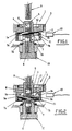
- this system has a designated gear by the general reference 1 in these figures, one of which toothed portion for example 2 is adapted to cooperate with training means designated by the reference general 3 in these figures.
- These training means can for example include another pinion adapted to cooperate with a worm screw activated by an electric motor, by direct current example. .
- this pinion 1 has a recess central designated by the general reference 4 on these figures, this central recess being adapted to receive rotating a tubular shaft for activating the organ functional designated by reference 5 in these figures, and in which is placed a mobile equipment designated by the general reference 6.
- This mobile assembly can be moved axially in the tree and is provided with a pin designated by the general reference 7 whose ends protrude radially on either side of the tree through corresponding axial lights thereof.
- the radial protrusions of the pin are designated by the references 7a and 7b respectively and the axial lights of the shaft by the references 5a and 5b.
- this moving part 6 and therefore this pin 7 are mounted movable against the action of means of solicitation elastic 8 formed for example by a spring housed in the tubular shaft, between a first position clutch shown in Figure 1, in which the radial projections 7a and 7b of the pin extend in radial recesses respectively 1a and 1b of the pinion 1 and a second retracted position of clutch, in which these projecting parts 7a, 7b of the pin extend out of the corresponding recesses 1a, 1b of the pinion, to allow activation manual of the functional organ.
- means of solicitation elastic 8 formed for example by a spring housed in the tubular shaft
- the tool and the tubular shaft can be threaded and tapped for allow the coupling of this tool and this shaft, this coupling then making it possible to repel very easily the moving part towards its retracted position.
- the roof actuation mechanism opening is connected to a pinion for example 10 provided on the tubular shaft 5, for example at its opposite end to that associated with the pinion 1.
- pin 7 is simply engaged in a recess transverse of the moving part 6 and in the axial lights of the shaft 5 and that there is keep in position to prevent it from coming off of these parts during the operation of this system.
- the holding means in corresponding positions are formed by a annular portion of the pinion, machined therein to extend around the pin to keep it in position.
- the means for holding in position the pin include a ring designated by the reference general 11 in these figures, this ring being fitted by force on a bearing 12 of the pinion and extending around the pin to hold it in position.
- this structure allows greatly simplify the manufacture of this pinion and therefore reduce its manufacturing cost, insofar as this no longer comprising an annular portion coming from material extending around the pin, it can be performed by a technique other than machining such as for example by molding or the like.
- this ring 11 can also present a succession of magnetic poles with polarities opposed.
- a type 13 magnetic sensor by example Hall effect, can then be associated with this ring to detect its rotation and deliver rotation information corresponding to means processing (not shown).
- This ring can for example be made in plastoferrite, and magnetized conventionally for obtain the corresponding magnetic poles.
- the sensor output information is usable to control the functioning of the system activation in the conventional way.
Landscapes
- Physics & Mathematics (AREA)
- General Physics & Mathematics (AREA)
- Engineering & Computer Science (AREA)
- Automation & Control Theory (AREA)
- Connection Of Motors, Electrical Generators, Mechanical Devices, And The Like (AREA)
- Gear Transmission (AREA)
- Harvesting Machines For Specific Crops (AREA)
- Agricultural Machines (AREA)
- Gears, Cams (AREA)
Claims (2)
- System zur entkuppelbaren Aktivierung eines funktionalen Organs eines Kraftfahrzeugs, wobei das System von dem Typ ist, der ein Ritzel (1) umfaßt, wovon ein gezahnter Abschnitt (2) so beschaffen ist, daß er mit Antriebsmitteln (3) zusammenwirkt, und eine mittige Aussparung (4) aufweist, in der eine rohrförmige Welle (5) für die Aktivierung des funktionalen Organs drehbar angebracht ist, wobei in dem Ritzel (1) ein axial bewegliches Teil (6) angeordnet ist, das mit einem Stift (7) versehen ist, dessen Enden (7a, 7b) beiderseits der Welle in axiale Langlöcher (5a, 5b) derselben radial vorstehen, und das entgegen elastischen Vorbelastungsmitteln (8) zwischen einer ersten, eingerückten Stellung, in der sich die radial vorstehenden Abschnitte (7a, 7b) des Stifts (7) in entsprechende radiale Ausnehmungen (1a, 1b) des Ritzels (1) erstrecken, und einer zweiten, ausgerückten Stellung, in der sich die radial vorstehenden Teile (7a, 7b) des Stifts (7) außerhalb der entsprechenden Ausnehmungen (1a, 1b) des Ritzels (1) erstrecken, verschiebbar ist, um eine manuelle Aktivierung des funktionalen Organs zu ermöglichen, und Mittel (11) zum Halten des Stifts (7) an seiner Position in dem beweglichen Teil (6) umfaßt, dadurch gekennzeichnet, daß die Haltemittel einen Ring (11) umfassen, der mit Kraft auf einen Umfang (12) des Ritzels aufgepreßt ist und Magnetpole mit entgegengesetzten Polaritäten aufweist, und daß diesem Ring ein magnetischer Aufnehmer (13) zugeordnet ist, um Informationen bezüglich seiner Drehung zu liefern.
- System nach Anspruch 1, dadurch gekennzeichnet, daß der Ring aus Plastomer-Ferrit hergestellt ist.
Applications Claiming Priority (2)
| Application Number | Priority Date | Filing Date | Title |
|---|---|---|---|
| FR9614095 | 1996-11-19 | ||
| FR9614095A FR2756068B1 (fr) | 1996-11-19 | 1996-11-19 | Systeme d'activation debrayable d'un organe fonctionnel de vehicule automobile |
Publications (2)
| Publication Number | Publication Date |
|---|---|
| EP0843248A1 EP0843248A1 (de) | 1998-05-20 |
| EP0843248B1 true EP0843248B1 (de) | 2002-02-06 |
Family
ID=9497769
Family Applications (1)
| Application Number | Title | Priority Date | Filing Date |
|---|---|---|---|
| EP19970402760 Expired - Lifetime EP0843248B1 (de) | 1996-11-19 | 1997-11-17 | Entkuppelbares Aktivierungssystem eines funktionellen Kraftfahrzeugelementes |
Country Status (4)
| Country | Link |
|---|---|
| EP (1) | EP0843248B1 (de) |
| DE (1) | DE69710296T2 (de) |
| ES (1) | ES2170350T3 (de) |
| FR (1) | FR2756068B1 (de) |
Families Citing this family (1)
| Publication number | Priority date | Publication date | Assignee | Title |
|---|---|---|---|---|
| DE102012219739A1 (de) * | 2012-10-29 | 2014-04-30 | Robert Bosch Gmbh | Antriebsvorrichtung für ein verstellbares Element eines Fahrzeugs |
Family Cites Families (6)
| Publication number | Priority date | Publication date | Assignee | Title |
|---|---|---|---|---|
| US4914387A (en) * | 1988-04-04 | 1990-04-03 | The Torrington Company | Magnetic speed sensor with an adaptive threshold circuit for use with a bearing assembly |
| DE9006935U1 (de) * | 1990-06-21 | 1991-10-17 | Robert Bosch Gmbh, 7000 Stuttgart | Elektromotorischer Antrieb |
| FR2690989B1 (fr) * | 1992-05-11 | 1996-01-26 | Skf France | Codeur annulaire composite. |
| DE4403574C1 (de) * | 1994-02-05 | 1995-01-26 | Webasto Karosseriesysteme | Antriebsvorrichtung für ein zwischen Endstellungen verstellbares Teil eines Fahrzeuges |
| IT1279573B1 (it) * | 1995-05-30 | 1997-12-16 | Skf Ind Spa | Elemento anulare composito, in particolare elemento rilevatore magnetico inseribile in un cuscinetto di rotolamento. |
| FR2742244B1 (fr) | 1995-12-08 | 1998-02-27 | Rockwell Lvs | Systeme d'activation debrayable d'un organe fonctionnel de vehicule automobile |
-
1996
- 1996-11-19 FR FR9614095A patent/FR2756068B1/fr not_active Expired - Fee Related
-
1997
- 1997-11-17 DE DE1997610296 patent/DE69710296T2/de not_active Expired - Fee Related
- 1997-11-17 ES ES97402760T patent/ES2170350T3/es not_active Expired - Lifetime
- 1997-11-17 EP EP19970402760 patent/EP0843248B1/de not_active Expired - Lifetime
Also Published As
| Publication number | Publication date |
|---|---|
| EP0843248A1 (de) | 1998-05-20 |
| DE69710296T2 (de) | 2002-11-14 |
| DE69710296D1 (de) | 2002-03-21 |
| ES2170350T3 (es) | 2002-08-01 |
| FR2756068A1 (fr) | 1998-05-22 |
| FR2756068B1 (fr) | 1999-02-12 |
Similar Documents
| Publication | Publication Date | Title |
|---|---|---|
| EP0792779B1 (de) | Motorgetriebe zum Antrieb des Armes eines Kraftfahrzeugscheibenwischers | |
| EP0233820B1 (de) | Zentrifugalkupplung für die Betätigung der Verriegelung eines Kraftfahrzeugtürschlosses | |
| EP0121497B1 (de) | Linearbetätiger mit einem elektrischen Motor | |
| FR2564515A1 (fr) | Dispositif pour l'actionnement d'une serrure de portiere de vehicule automobile | |
| EP2479073B1 (de) | Diebstahlsicherung für Lenksäule eines Kraftfahrzeugs | |
| WO2012007551A1 (fr) | Dispositif d'actionnement motorisé d'ouvrant de véhicule automobile | |
| EP2148413B1 (de) | Integriertes lineares elektrisches Stellglied | |
| EP1234936A1 (de) | Kraftfahrzeugschloss mit entkuppelbarem Kurbelzapfen | |
| FR2817935A1 (fr) | Dispositif de manoeuvre | |
| EP2475557A1 (de) | Zylinderkolben für einen bremskraftverstärker und bremskraftverstärker mit derartigem kolben | |
| FR2859050A1 (fr) | Unite d'entrainement et de transmission comportant au moins deux moteurs pour actionner ou deplacer une piece equipant un vehicule automobile | |
| EP0843248A1 (de) | Entkuppelbares Aktivierungssystem eines funktionellen Kraftfahrzeugelementes | |
| FR2716541A1 (fr) | Dispositif d'entraînement d'objectif. | |
| FR2742244A1 (fr) | Systeme d'activation debrayable d'un organe fonctionnel de vehicule automobile | |
| FR2797109A1 (fr) | Machine electrique tournante et demarreur ayant un faible jeu de fonctionnement axial de l'arbre d'induit | |
| EP0085586B1 (de) | Schlossbedienung mit Druckknopf | |
| EP1538051B1 (de) | Notbetätigungseinrichtung für eine elektromechanische Betriebsbremse | |
| EP1452762B1 (de) | Mechanismus zur Umwandlung einer drehenden in einer geradlinigen Bewegung und diese verwendende Kupplung | |
| EP1111259B1 (de) | Kupplungsvorrichtung zum Übertragen einer Drehbewegung zwischen einem treibenden und einem getriebenen Glied | |
| FR2879544A1 (fr) | Dispositif de verrouillage d'un frein de stationnement automatique d'un vehicule | |
| EP0689959A1 (de) | Schneckenvorrichtung zur Positionierung in Fahrzeugscheinwerfer | |
| EP1457695A1 (de) | Wälzlager festgelegt in einem Lagersitz eines Gehäuses mittels eines reversibel bewegbaren Sprengrings | |
| FR2899546A1 (fr) | Actionneur de frein de stationnement electrique | |
| FR3155152A1 (fr) | Actionneur pour un bras robotisé à configuration améliorée | |
| FR2947602A1 (fr) | Dispositif d'entrainement d'un element reglable de vehicule automobile |
Legal Events
| Date | Code | Title | Description |
|---|---|---|---|
| PUAI | Public reference made under article 153(3) epc to a published international application that has entered the european phase |
Free format text: ORIGINAL CODE: 0009012 |
|
| AK | Designated contracting states |
Kind code of ref document: A1 Designated state(s): DE ES GB IT |
|
| AX | Request for extension of the european patent |
Free format text: AL;LT;LV;MK;RO;SI |
|
| 17P | Request for examination filed |
Effective date: 19981029 |
|
| AKX | Designation fees paid |
Free format text: DE ES GB IT |
|
| RBV | Designated contracting states (corrected) |
Designated state(s): DE ES GB IT |
|
| GRAG | Despatch of communication of intention to grant |
Free format text: ORIGINAL CODE: EPIDOS AGRA |
|
| 17Q | First examination report despatched |
Effective date: 20010220 |
|
| GRAG | Despatch of communication of intention to grant |
Free format text: ORIGINAL CODE: EPIDOS AGRA |
|
| GRAH | Despatch of communication of intention to grant a patent |
Free format text: ORIGINAL CODE: EPIDOS IGRA |
|
| GRAH | Despatch of communication of intention to grant a patent |
Free format text: ORIGINAL CODE: EPIDOS IGRA |
|
| GRAA | (expected) grant |
Free format text: ORIGINAL CODE: 0009210 |
|
| REG | Reference to a national code |
Ref country code: GB Ref legal event code: IF02 |
|
| AK | Designated contracting states |
Kind code of ref document: B1 Designated state(s): DE ES GB IT |
|
| GBT | Gb: translation of ep patent filed (gb section 77(6)(a)/1977) |
Effective date: 20020206 |
|
| REF | Corresponds to: |
Ref document number: 69710296 Country of ref document: DE Date of ref document: 20020321 |
|
| REG | Reference to a national code |
Ref country code: ES Ref legal event code: FG2A Ref document number: 2170350 Country of ref document: ES Kind code of ref document: T3 |
|
| PLBE | No opposition filed within time limit |
Free format text: ORIGINAL CODE: 0009261 |
|
| STAA | Information on the status of an ep patent application or granted ep patent |
Free format text: STATUS: NO OPPOSITION FILED WITHIN TIME LIMIT |
|
| 26N | No opposition filed |
Effective date: 20021107 |
|
| PGFP | Annual fee paid to national office [announced via postgrant information from national office to epo] |
Ref country code: GB Payment date: 20041110 Year of fee payment: 8 |
|
| PGFP | Annual fee paid to national office [announced via postgrant information from national office to epo] |
Ref country code: ES Payment date: 20041209 Year of fee payment: 8 |
|
| PGFP | Annual fee paid to national office [announced via postgrant information from national office to epo] |
Ref country code: DE Payment date: 20041230 Year of fee payment: 8 |
|
| PG25 | Lapsed in a contracting state [announced via postgrant information from national office to epo] |
Ref country code: IT Free format text: LAPSE BECAUSE OF NON-PAYMENT OF DUE FEES Effective date: 20051117 Ref country code: GB Free format text: LAPSE BECAUSE OF NON-PAYMENT OF DUE FEES Effective date: 20051117 |
|
| PG25 | Lapsed in a contracting state [announced via postgrant information from national office to epo] |
Ref country code: ES Free format text: LAPSE BECAUSE OF NON-PAYMENT OF DUE FEES Effective date: 20051118 |
|
| PG25 | Lapsed in a contracting state [announced via postgrant information from national office to epo] |
Ref country code: DE Free format text: LAPSE BECAUSE OF NON-PAYMENT OF DUE FEES Effective date: 20060601 |
|
| GBPC | Gb: european patent ceased through non-payment of renewal fee |
Effective date: 20051117 |
|
| REG | Reference to a national code |
Ref country code: ES Ref legal event code: FD2A Effective date: 20051118 |