EP0843324A1 - Stromversorgungsschaltung für Elektromagnet - Google Patents
Stromversorgungsschaltung für Elektromagnet Download PDFInfo
- Publication number
- EP0843324A1 EP0843324A1 EP97402718A EP97402718A EP0843324A1 EP 0843324 A1 EP0843324 A1 EP 0843324A1 EP 97402718 A EP97402718 A EP 97402718A EP 97402718 A EP97402718 A EP 97402718A EP 0843324 A1 EP0843324 A1 EP 0843324A1
- Authority
- EP
- European Patent Office
- Prior art keywords
- thyristor
- circuit
- winding
- supply
- high voltage
- Prior art date
- Legal status (The legal status is an assumption and is not a legal conclusion. Google has not performed a legal analysis and makes no representation as to the accuracy of the status listed.)
- Granted
Links
- 238000004804 winding Methods 0.000 claims abstract description 29
- 239000003990 capacitor Substances 0.000 claims description 9
- 230000000903 blocking effect Effects 0.000 claims description 3
- 238000010586 diagram Methods 0.000 description 3
- 238000012423 maintenance Methods 0.000 description 2
- 230000004913 activation Effects 0.000 description 1
- 238000001514 detection method Methods 0.000 description 1
- 230000017525 heat dissipation Effects 0.000 description 1
- 230000037452 priming Effects 0.000 description 1
- 230000001960 triggered effect Effects 0.000 description 1
Images
Classifications
-
- H—ELECTRICITY
- H01—ELECTRIC ELEMENTS
- H01F—MAGNETS; INDUCTANCES; TRANSFORMERS; SELECTION OF MATERIALS FOR THEIR MAGNETIC PROPERTIES
- H01F7/00—Magnets
- H01F7/06—Electromagnets; Actuators including electromagnets
- H01F7/08—Electromagnets; Actuators including electromagnets with armatures
- H01F7/18—Circuit arrangements for obtaining desired operating characteristics, e.g. for slow operation, for sequential energisation of windings, for high-speed energisation of windings
- H01F7/1805—Circuit arrangements for holding the operation of electromagnets or for holding the armature in attracted position with reduced energising current
Definitions
- the invention relates to a supply circuit for a coil for an electromagnet. provided with a single winding, comprising a power source of continuous low voltage, an alternating high voltage power source, both mounted across the winding, and a switching device mounted in series with the high voltage source and suitable for securing or blocking high voltage winding supply.
- a coil can be made up of two windings, one main winding sized to support most of the calling power, and an auxiliary winding sufficiently dimensioned to provide the power necessary to maintain the movable frame.
- This type of double winding coil however, has a significant size disadvantage.
- the invention therefore aims to supply a coil electromagnet with single winding from an inexpensive supply circuit and can be used indifferently for voltages varying from 100 to 500 Volts.
- the supply circuit is characterized in that the switching device includes a thyristor mounted between the high source voltage and winding, and a thyristor control circuit mounted across the thyristor and connected to its trigger; the control circuit allows the conduction of the thyristor during the delivery by the high voltage source of an alternation positive of a voltage wave.
- the supply circuit of the invention therefore does not require a device reduction in consumption because the supply is stopped at high voltage while the winding remains supplied with low voltage, stopping taking place automatically at zero crossing of the alternating voltage passing through the thyristor.
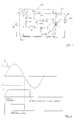
- FIG. 1 The diagram visible in Figure 1 represents the supply circuit of a coil 10, provided with a single winding 11, with an electromagnet for a device contactor type switch.
- the electromagnet includes the coil 10, a circuit fixed magnetic and a movable magnetic circuit intended to be attracted by the circuit magnetic fixed when the coil is energized.
- the movement of the mobile magnetic circuit is triggered by the crossing of the winding 11 of the coil, for a short time, by a current high current call from a high voltage power source alternative 30 disposed across the winding 11; keeping it in position attracted is achieved by the continuous supply of the coil by a current of maintenance, of intensity lower than that of the inrush current, delivered by a source of continuous low voltage 20 also arranged at the terminals of the winding 11, between a high line L1 and a low line L2.
- the alternative high-voltage power source 30 can be the electrical distribution network and continuous low voltage power source 20 can be a low voltage source of around 12 Volts intended for the power supply of electronic circuits and supplied for example by a transformer whose primary constitutes an element of a current path of a derived electrical circuit in which direct current flows.
- a diode D1 is preferably connected in series with the source at low voltage 20 to avoid when the coil is supplied by the high voltage source 30 the return of the high charging voltage to the source 20.
- a switching device 40 is mounted in series with the source to high voltage 30. It is capable of ensuring or blocking the supply of the winding 11 in high voltage.
- the device 40 comprises in series, between the high power source voltage 30 and winding 11, an on-off switch 41 and a thyristor 42 initiable by a control circuit 43 mounted in parallel to the thyristor between two connection points of anode A and cathode B and connected to its trigger G.
- control circuit 43 comprises in series a diode D2 the anode of which is connected to the connection point A, a normally closed switch 44 and an RC timing circuit comprising in series a variable resistor R connected to switch 44 and a capacitor C connected to connection point B.
- the control circuit 43 comprises a diode D3, of the Zener type or with controlled avalanche, located between the trigger G of thyristor 42 and a point of connection E between resistor R and capacitor C, and a freewheeling diode D4 whose cathode and anode are respectively connected to connection points E and B.
- the low DC voltage delivered by the source 20 is applied to winding 11 but it remains insufficient to produce the ampere-turns necessary to trigger the movement of the mobile magnetic circuit.
- Closing the switch 41 causes current to flow through the timing circuit RC, which causes the charging of capacitor C.
- the trigger G of the thyristor receives via the diode D3 a control pulse and the thyristor 42 then becomes passerby.
- the voltage V D3 is characteristic of the delay in the ignition of the thyristor 42 which represents the time elapsed between the closing of the switch 41 and the activation of the thyristor.
- the voltage V D3 depends on the charging time of the capacitor C, itself a function of the value of the resistance R which it is possible to vary.
- the delay in the ignition of the thyristor is adjustable as a function of the value of the resistance.
- the resistance R is adjusted so that the triggering of the trigger G of the thyristor takes place during the rise of a positive alternation of the voltage wave which must pass through the thyristor.
- the ignition of thyristor 42 is driven by detection means suitable for opening the switch 44 to avoid passing for a second positive altemance of voltage V in circuit 43.
- the thyristor 42 conducts and supplies the winding 11 which is sufficiently excited to generate movement of the mobile magnetic circuit.
- the capacitor C can discharge thanks to the freewheeling diode D4 when the voltage V becomes, in absolute value, greater than the value V D3 .
- the coil remains only powered by the source current at low DC voltage 20, which allows the circuit to be kept in the attracted position mobile magnetic.
- the supply of the coil by the source 20 is interrupted by a switching device 21, of the type mechanical or electrical, placed in series between source 20 and diode D1 ( Figure 1).
- the switch 21 can be placed in parallel with the winding 11, between the cathode of diode D1 and the low line L2 or alternatively, in series with the coil (not illustrated).
Landscapes
- Physics & Mathematics (AREA)
- Electromagnetism (AREA)
- Engineering & Computer Science (AREA)
- Power Engineering (AREA)
- Relay Circuits (AREA)
- Supply And Distribution Of Alternating Current (AREA)
Applications Claiming Priority (2)
| Application Number | Priority Date | Filing Date | Title |
|---|---|---|---|
| FR9614122A FR2756091B1 (fr) | 1996-11-18 | 1996-11-18 | Circuit d'alimentation d'une bobine pour electro-aimant |
| FR9614122 | 1996-11-18 |
Publications (2)
| Publication Number | Publication Date |
|---|---|
| EP0843324A1 true EP0843324A1 (de) | 1998-05-20 |
| EP0843324B1 EP0843324B1 (de) | 2001-03-14 |
Family
ID=9497790
Family Applications (1)
| Application Number | Title | Priority Date | Filing Date |
|---|---|---|---|
| EP97402718A Expired - Lifetime EP0843324B1 (de) | 1996-11-18 | 1997-11-13 | Stromversorgungsschaltung für Elektromagnet |
Country Status (5)
| Country | Link |
|---|---|
| US (1) | US5946182A (de) |
| EP (1) | EP0843324B1 (de) |
| DE (1) | DE69704251T2 (de) |
| ES (1) | ES2155974T3 (de) |
| FR (1) | FR2756091B1 (de) |
Families Citing this family (3)
| Publication number | Priority date | Publication date | Assignee | Title |
|---|---|---|---|---|
| US10357144B2 (en) | 2013-03-14 | 2019-07-23 | Given Imaging Ltd. | Method and circuit for muting electromagnetic interference during maneuvering of a device |
| US10070932B2 (en) | 2013-08-29 | 2018-09-11 | Given Imaging Ltd. | System and method for maneuvering coils power optimization |
| CN105811963B (zh) * | 2016-03-16 | 2019-01-01 | 西安电炉研究所有限公司 | 电子放大式晶闸管驱动器及其控制方法 |
Citations (4)
| Publication number | Priority date | Publication date | Assignee | Title |
|---|---|---|---|---|
| US4391236A (en) * | 1981-07-24 | 1983-07-05 | Outboard Marine Corporation | CD Ignition with automatic spark retard |
| EP0091648A1 (de) * | 1982-04-10 | 1983-10-19 | HONEYWELL and PHILIPS MEDICAL ELECTRONICS B.V. | Erregerschaltung für Magnetventile |
| JPS5914615A (ja) * | 1982-07-15 | 1984-01-25 | Matsushita Electric Works Ltd | 有極電磁石の交流駆動回路 |
| JPS5948903A (ja) * | 1982-09-14 | 1984-03-21 | Mitsubishi Electric Corp | 電磁石装置 |
Family Cites Families (5)
| Publication number | Priority date | Publication date | Assignee | Title |
|---|---|---|---|---|
| US4185315A (en) * | 1976-09-23 | 1980-01-22 | Honeywell Inc. | Apparatus with a single input connectable to electrical energizing sources of different character |
| US4112477A (en) * | 1977-06-06 | 1978-09-05 | General Motors Corporation | Circuit for energizing a fuel injector valve coil |
| JP2561453B2 (ja) * | 1983-02-07 | 1996-12-11 | 住友重機械工業株式会社 | 電気集塵機用パルス電源 |
| US4516185A (en) * | 1983-09-30 | 1985-05-07 | Siemens-Allis, Inc. | Time ratio control circuit for contactor or the like |
| US5734543A (en) * | 1996-03-27 | 1998-03-31 | Clemson University | Method and apparatus to improve the performance of AC solenoid devices during lapses in power quality |
-
1996
- 1996-11-18 FR FR9614122A patent/FR2756091B1/fr not_active Expired - Fee Related
-
1997
- 1997-11-13 DE DE69704251T patent/DE69704251T2/de not_active Expired - Fee Related
- 1997-11-13 EP EP97402718A patent/EP0843324B1/de not_active Expired - Lifetime
- 1997-11-13 ES ES97402718T patent/ES2155974T3/es not_active Expired - Lifetime
- 1997-11-18 US US08/972,326 patent/US5946182A/en not_active Expired - Fee Related
Patent Citations (4)
| Publication number | Priority date | Publication date | Assignee | Title |
|---|---|---|---|---|
| US4391236A (en) * | 1981-07-24 | 1983-07-05 | Outboard Marine Corporation | CD Ignition with automatic spark retard |
| EP0091648A1 (de) * | 1982-04-10 | 1983-10-19 | HONEYWELL and PHILIPS MEDICAL ELECTRONICS B.V. | Erregerschaltung für Magnetventile |
| JPS5914615A (ja) * | 1982-07-15 | 1984-01-25 | Matsushita Electric Works Ltd | 有極電磁石の交流駆動回路 |
| JPS5948903A (ja) * | 1982-09-14 | 1984-03-21 | Mitsubishi Electric Corp | 電磁石装置 |
Non-Patent Citations (2)
| Title |
|---|
| PATENT ABSTRACTS OF JAPAN vol. 008, no. 095 (E - 242) 2 May 1984 (1984-05-02) * |
| PATENT ABSTRACTS OF JAPAN vol. 008, no. 139 (E - 253) 28 June 1984 (1984-06-28) * |
Also Published As
| Publication number | Publication date |
|---|---|
| DE69704251D1 (de) | 2001-04-19 |
| FR2756091B1 (fr) | 1998-12-24 |
| DE69704251T2 (de) | 2001-07-12 |
| FR2756091A1 (fr) | 1998-05-22 |
| ES2155974T3 (es) | 2001-06-01 |
| EP0843324B1 (de) | 2001-03-14 |
| US5946182A (en) | 1999-08-31 |
Similar Documents
| Publication | Publication Date | Title |
|---|---|---|
| CA1047597A (fr) | Circuits d'alimentation d'electroaimants et electroaimants comprenant ces circuits | |
| FR2696062A1 (fr) | Commutateur électrique de puissance commandé et procédé de commutation d'un circuit électrique de puissance. | |
| CA2252622A1 (fr) | Dispositif de commande d'une charge inductive | |
| FR2517842A1 (fr) | Circuit de commande pour un outil motorise actionne electromagnetiquement | |
| FR2538942A1 (fr) | Dispositif de commande d'organe(s) electromagnetique(s) a actionnement rapide, tel(s) qu'electrovanne(s) ou injecteur(s) | |
| EP3288059A1 (de) | Steuerbarer auslöser für einen elektrischen trennschalter | |
| CH628423A5 (fr) | Circuit electrique pour l'allumage d'un detonateur. | |
| EP0166358A1 (de) | Bedienungsorgan für eine Verbindung eines elektrischen Stromkreises mit einem Netzwerk | |
| EP0843324B1 (de) | Stromversorgungsschaltung für Elektromagnet | |
| EP0836280B1 (de) | Elektronischer Schalter mit Zweidraht-Versorgung | |
| FR2786915A1 (fr) | Dispositif de commande d'un electro-aimant, avec detection d'un deplacement intempestif du noyau mobile de l'electro-aimant | |
| EP0093804B1 (de) | Elektrische Schaltung für die Zündung eines Detonators | |
| FR2618270A1 (fr) | Circuit et appareillage pour l'alimentation protegee d'une charge a l'aide d'interrupteurs statiques et electromecaniques. | |
| CH618273A5 (de) | ||
| FR2488476A1 (fr) | Circuits de commande et ensembles de commutation electrique comprenant de tels circuits | |
| FR2460088A1 (fr) | Circuit d'allumage pour tubes fluorescents et similaires avec chauffage preliminaire des filaments | |
| FR2579820A1 (fr) | Dispositif de commande d'organes electromagnetiques a actionnement rapide | |
| FR2513828A1 (fr) | Circuit economiseur d'energie | |
| EP0834975B1 (de) | Elektrisches Verteilungsanschlusselement mit hybridem Begrenzerblock | |
| EP0054445B1 (de) | Elektronische Induktionsheizvorrichtung | |
| CA2187662C (fr) | Circuit d'alimentation d'une bobine d'excitation d'un electro-aimant | |
| EP0025404B1 (de) | Kurzschlusselement für Serienschaltung | |
| FR2459321A1 (fr) | Dispositif de chauffage accelere du bain lessiviel d'une machine a laver le linge a tambour rotatif | |
| EP0026531A1 (de) | Zündgerät für Lampen, z.B. Leuchtstofflampen | |
| EP0994499A1 (de) | Elektronische Speisungseinrichtung für ein elektromagnetisches Schaltgerät |
Legal Events
| Date | Code | Title | Description |
|---|---|---|---|
| PUAI | Public reference made under article 153(3) epc to a published international application that has entered the european phase |
Free format text: ORIGINAL CODE: 0009012 |
|
| AK | Designated contracting states |
Kind code of ref document: A1 Designated state(s): DE ES FR GB IT |
|
| AX | Request for extension of the european patent |
Free format text: AL;LT;LV;MK;RO;SI |
|
| 17P | Request for examination filed |
Effective date: 19980605 |
|
| AKX | Designation fees paid |
Free format text: DE ES FR GB IT |
|
| RBV | Designated contracting states (corrected) |
Designated state(s): DE ES FR GB IT |
|
| RAP1 | Party data changed (applicant data changed or rights of an application transferred) |
Owner name: SCHNEIDER ELECTRIC INDUSTRIES SA |
|
| 17Q | First examination report despatched |
Effective date: 20000110 |
|
| RAP1 | Party data changed (applicant data changed or rights of an application transferred) |
Owner name: SCHNEIDER ELECTRIC INDUSTRIES SA |
|
| GRAG | Despatch of communication of intention to grant |
Free format text: ORIGINAL CODE: EPIDOS AGRA |
|
| GRAG | Despatch of communication of intention to grant |
Free format text: ORIGINAL CODE: EPIDOS AGRA |
|
| GRAH | Despatch of communication of intention to grant a patent |
Free format text: ORIGINAL CODE: EPIDOS IGRA |
|
| GRAH | Despatch of communication of intention to grant a patent |
Free format text: ORIGINAL CODE: EPIDOS IGRA |
|
| GRAA | (expected) grant |
Free format text: ORIGINAL CODE: 0009210 |
|
| AK | Designated contracting states |
Kind code of ref document: B1 Designated state(s): DE ES FR GB IT |
|
| ITF | It: translation for a ep patent filed | ||
| GBT | Gb: translation of ep patent filed (gb section 77(6)(a)/1977) |
Effective date: 20010314 |
|
| REF | Corresponds to: |
Ref document number: 69704251 Country of ref document: DE Date of ref document: 20010419 |
|
| REG | Reference to a national code |
Ref country code: ES Ref legal event code: FG2A Ref document number: 2155974 Country of ref document: ES Kind code of ref document: T3 |
|
| PG25 | Lapsed in a contracting state [announced via postgrant information from national office to epo] |
Ref country code: GB Free format text: LAPSE BECAUSE OF NON-PAYMENT OF DUE FEES Effective date: 20011113 |
|
| PG25 | Lapsed in a contracting state [announced via postgrant information from national office to epo] |
Ref country code: ES Free format text: LAPSE BECAUSE OF NON-PAYMENT OF DUE FEES Effective date: 20011114 |
|
| REG | Reference to a national code |
Ref country code: GB Ref legal event code: IF02 |
|
| PLBE | No opposition filed within time limit |
Free format text: ORIGINAL CODE: 0009261 |
|
| STAA | Information on the status of an ep patent application or granted ep patent |
Free format text: STATUS: NO OPPOSITION FILED WITHIN TIME LIMIT |
|
| 26N | No opposition filed | ||
| PG25 | Lapsed in a contracting state [announced via postgrant information from national office to epo] |
Ref country code: DE Free format text: LAPSE BECAUSE OF NON-PAYMENT OF DUE FEES Effective date: 20020702 |
|
| PG25 | Lapsed in a contracting state [announced via postgrant information from national office to epo] |
Ref country code: FR Free format text: LAPSE BECAUSE OF NON-PAYMENT OF DUE FEES Effective date: 20020730 |
|
| REG | Reference to a national code |
Ref country code: FR Ref legal event code: ST |
|
| REG | Reference to a national code |
Ref country code: FR Ref legal event code: ST |
|
| REG | Reference to a national code |
Ref country code: ES Ref legal event code: FD2A Effective date: 20021213 |
|
| PG25 | Lapsed in a contracting state [announced via postgrant information from national office to epo] |
Ref country code: IT Free format text: LAPSE BECAUSE OF NON-PAYMENT OF DUE FEES Effective date: 20051113 |