EP0843332A1 - Circuit breaker having a breaker block and modules for processing, calibration and indication - Google Patents
Circuit breaker having a breaker block and modules for processing, calibration and indication Download PDFInfo
- Publication number
- EP0843332A1 EP0843332A1 EP97410126A EP97410126A EP0843332A1 EP 0843332 A1 EP0843332 A1 EP 0843332A1 EP 97410126 A EP97410126 A EP 97410126A EP 97410126 A EP97410126 A EP 97410126A EP 0843332 A1 EP0843332 A1 EP 0843332A1
- Authority
- EP
- European Patent Office
- Prior art keywords
- circuit breaker
- module
- block
- calibration
- communication
- Prior art date
- Legal status (The legal status is an assumption and is not a legal conclusion. Google has not performed a legal analysis and makes no representation as to the accuracy of the status listed.)
- Granted
Links
- 238000004891 communication Methods 0.000 claims abstract description 71
- 238000002955 isolation Methods 0.000 claims abstract 2
- 230000003287 optical effect Effects 0.000 claims description 11
- 230000011664 signaling Effects 0.000 claims description 10
- 230000000295 complement effect Effects 0.000 claims description 7
- 210000000056 organ Anatomy 0.000 claims description 7
- 239000012528 membrane Substances 0.000 claims description 6
- 238000005259 measurement Methods 0.000 claims description 3
- 230000001131 transforming effect Effects 0.000 claims 1
- 230000006870 function Effects 0.000 description 12
- 239000004020 conductor Substances 0.000 description 9
- 230000002457 bidirectional effect Effects 0.000 description 5
- 230000006978 adaptation Effects 0.000 description 3
- 230000006872 improvement Effects 0.000 description 3
- 230000010354 integration Effects 0.000 description 3
- 230000003993 interaction Effects 0.000 description 3
- 238000010586 diagram Methods 0.000 description 2
- 230000004069 differentiation Effects 0.000 description 2
- 230000009131 signaling function Effects 0.000 description 2
- 230000009466 transformation Effects 0.000 description 2
- XEEYBQQBJWHFJM-UHFFFAOYSA-N Iron Chemical group [Fe] XEEYBQQBJWHFJM-UHFFFAOYSA-N 0.000 description 1
- 230000008859 change Effects 0.000 description 1
- 239000000470 constituent Substances 0.000 description 1
- 230000008878 coupling Effects 0.000 description 1
- 238000010168 coupling process Methods 0.000 description 1
- 238000005859 coupling reaction Methods 0.000 description 1
- 230000007423 decrease Effects 0.000 description 1
- 230000005520 electrodynamics Effects 0.000 description 1
- 239000003344 environmental pollutant Substances 0.000 description 1
- 239000007789 gas Substances 0.000 description 1
- 230000001939 inductive effect Effects 0.000 description 1
- 231100000719 pollutant Toxicity 0.000 description 1
Images



Classifications
-
- H—ELECTRICITY
- H01—ELECTRIC ELEMENTS
- H01H—ELECTRIC SWITCHES; RELAYS; SELECTORS; EMERGENCY PROTECTIVE DEVICES
- H01H71/00—Details of the protective switches or relays covered by groups H01H73/00 - H01H83/00
- H01H71/02—Housings; Casings; Bases; Mountings
- H01H71/0207—Mounting or assembling the different parts of the circuit breaker
- H01H71/0228—Mounting or assembling the different parts of the circuit breaker having provisions for interchangeable or replaceable parts
-
- H—ELECTRICITY
- H01—ELECTRIC ELEMENTS
- H01H—ELECTRIC SWITCHES; RELAYS; SELECTORS; EMERGENCY PROTECTIVE DEVICES
- H01H9/00—Details of switching devices, not covered by groups H01H1/00 - H01H7/00
- H01H9/18—Distinguishing marks on switches, e.g. for indicating switch location in the dark; Adaptation of switches to receive distinguishing marks
- H01H2009/188—Distinguishing marks on switches, e.g. for indicating switch location in the dark; Adaptation of switches to receive distinguishing marks with indication of rating
-
- H—ELECTRICITY
- H01—ELECTRIC ELEMENTS
- H01H—ELECTRIC SWITCHES; RELAYS; SELECTORS; EMERGENCY PROTECTIVE DEVICES
- H01H9/00—Details of switching devices, not covered by groups H01H1/00 - H01H7/00
- H01H9/30—Means for extinguishing or preventing arc between current-carrying parts
- H01H2009/305—Means for extinguishing or preventing arc between current-carrying parts including means for screening for arc gases as protection of mechanism against hot arc gases or for keeping arc gases in the arc chamber
-
- H—ELECTRICITY
- H01—ELECTRIC ELEMENTS
- H01H—ELECTRIC SWITCHES; RELAYS; SELECTORS; EMERGENCY PROTECTIVE DEVICES
- H01H71/00—Details of the protective switches or relays covered by groups H01H73/00 - H01H83/00
- H01H71/04—Means for indicating condition of the switching device
- H01H2071/042—Means for indicating condition of the switching device with different indications for different conditions, e.g. contact position, overload, short circuit or earth leakage
-
- H—ELECTRICITY
- H01—ELECTRIC ELEMENTS
- H01H—ELECTRIC SWITCHES; RELAYS; SELECTORS; EMERGENCY PROTECTIVE DEVICES
- H01H71/00—Details of the protective switches or relays covered by groups H01H73/00 - H01H83/00
- H01H71/08—Terminals; Connections
- H01H2071/086—Low power connections for auxiliary switches, e.g. shunt trip
-
- H—ELECTRICITY
- H01—ELECTRIC ELEMENTS
- H01H—ELECTRIC SWITCHES; RELAYS; SELECTORS; EMERGENCY PROTECTIVE DEVICES
- H01H71/00—Details of the protective switches or relays covered by groups H01H73/00 - H01H83/00
- H01H71/10—Operating or release mechanisms
- H01H71/12—Automatic release mechanisms with or without manual release
- H01H71/46—Automatic release mechanisms with or without manual release having means for operating auxiliary contacts additional to the main contacts
- H01H2071/467—Automatic release mechanisms with or without manual release having means for operating auxiliary contacts additional to the main contacts with history indication, e.g. of trip and/or kind of trip, number of short circuits etc.
-
- H—ELECTRICITY
- H01—ELECTRIC ELEMENTS
- H01H—ELECTRIC SWITCHES; RELAYS; SELECTORS; EMERGENCY PROTECTIVE DEVICES
- H01H2300/00—Orthogonal indexing scheme relating to electric switches, relays, selectors or emergency protective devices covered by H01H
- H01H2300/03—Application domotique, e.g. for house automation, bus connected switches, sensors, loads or intelligent wiring
-
- H—ELECTRICITY
- H01—ELECTRIC ELEMENTS
- H01H—ELECTRIC SWITCHES; RELAYS; SELECTORS; EMERGENCY PROTECTIVE DEVICES
- H01H71/00—Details of the protective switches or relays covered by groups H01H73/00 - H01H83/00
- H01H71/10—Operating or release mechanisms
- H01H71/12—Automatic release mechanisms with or without manual release
- H01H71/123—Automatic release mechanisms with or without manual release using a solid-state trip unit
-
- H—ELECTRICITY
- H01—ELECTRIC ELEMENTS
- H01H—ELECTRIC SWITCHES; RELAYS; SELECTORS; EMERGENCY PROTECTIVE DEVICES
- H01H71/00—Details of the protective switches or relays covered by groups H01H73/00 - H01H83/00
- H01H71/10—Operating or release mechanisms
- H01H71/12—Automatic release mechanisms with or without manual release
- H01H71/46—Automatic release mechanisms with or without manual release having means for operating auxiliary contacts additional to the main contacts
-
- H—ELECTRICITY
- H02—GENERATION; CONVERSION OR DISTRIBUTION OF ELECTRIC POWER
- H02H—EMERGENCY PROTECTIVE CIRCUIT ARRANGEMENTS
- H02H3/00—Emergency protective circuit arrangements for automatic disconnection directly responsive to an undesired change from normal electric working condition with or without subsequent reconnection ; integrated protection
- H02H3/006—Calibration or setting of parameters
-
- Y—GENERAL TAGGING OF NEW TECHNOLOGICAL DEVELOPMENTS; GENERAL TAGGING OF CROSS-SECTIONAL TECHNOLOGIES SPANNING OVER SEVERAL SECTIONS OF THE IPC; TECHNICAL SUBJECTS COVERED BY FORMER USPC CROSS-REFERENCE ART COLLECTIONS [XRACs] AND DIGESTS
- Y02—TECHNOLOGIES OR APPLICATIONS FOR MITIGATION OR ADAPTATION AGAINST CLIMATE CHANGE
- Y02B—CLIMATE CHANGE MITIGATION TECHNOLOGIES RELATED TO BUILDINGS, e.g. HOUSING, HOUSE APPLIANCES OR RELATED END-USER APPLICATIONS
- Y02B70/00—Technologies for an efficient end-user side electric power management and consumption
- Y02B70/30—Systems integrating technologies related to power network operation and communication or information technologies for improving the carbon footprint of the management of residential or tertiary loads, i.e. smart grids as climate change mitigation technology in the buildings sector, including also the last stages of power distribution and the control, monitoring or operating management systems at local level
-
- Y—GENERAL TAGGING OF NEW TECHNOLOGICAL DEVELOPMENTS; GENERAL TAGGING OF CROSS-SECTIONAL TECHNOLOGIES SPANNING OVER SEVERAL SECTIONS OF THE IPC; TECHNICAL SUBJECTS COVERED BY FORMER USPC CROSS-REFERENCE ART COLLECTIONS [XRACs] AND DIGESTS
- Y02—TECHNOLOGIES OR APPLICATIONS FOR MITIGATION OR ADAPTATION AGAINST CLIMATE CHANGE
- Y02B—CLIMATE CHANGE MITIGATION TECHNOLOGIES RELATED TO BUILDINGS, e.g. HOUSING, HOUSE APPLIANCES OR RELATED END-USER APPLICATIONS
- Y02B90/00—Enabling technologies or technologies with a potential or indirect contribution to GHG emissions mitigation
- Y02B90/20—Smart grids as enabling technology in buildings sector
-
- Y—GENERAL TAGGING OF NEW TECHNOLOGICAL DEVELOPMENTS; GENERAL TAGGING OF CROSS-SECTIONAL TECHNOLOGIES SPANNING OVER SEVERAL SECTIONS OF THE IPC; TECHNICAL SUBJECTS COVERED BY FORMER USPC CROSS-REFERENCE ART COLLECTIONS [XRACs] AND DIGESTS
- Y04—INFORMATION OR COMMUNICATION TECHNOLOGIES HAVING AN IMPACT ON OTHER TECHNOLOGY AREAS
- Y04S—SYSTEMS INTEGRATING TECHNOLOGIES RELATED TO POWER NETWORK OPERATION, COMMUNICATION OR INFORMATION TECHNOLOGIES FOR IMPROVING THE ELECTRICAL POWER GENERATION, TRANSMISSION, DISTRIBUTION, MANAGEMENT OR USAGE, i.e. SMART GRIDS
- Y04S20/00—Management or operation of end-user stationary applications or the last stages of power distribution; Controlling, monitoring or operating thereof
- Y04S20/14—Protecting elements, switches, relays or circuit breakers
-
- Y—GENERAL TAGGING OF NEW TECHNOLOGICAL DEVELOPMENTS; GENERAL TAGGING OF CROSS-SECTIONAL TECHNOLOGIES SPANNING OVER SEVERAL SECTIONS OF THE IPC; TECHNICAL SUBJECTS COVERED BY FORMER USPC CROSS-REFERENCE ART COLLECTIONS [XRACs] AND DIGESTS
- Y04—INFORMATION OR COMMUNICATION TECHNOLOGIES HAVING AN IMPACT ON OTHER TECHNOLOGY AREAS
- Y04S—SYSTEMS INTEGRATING TECHNOLOGIES RELATED TO POWER NETWORK OPERATION, COMMUNICATION OR INFORMATION TECHNOLOGIES FOR IMPROVING THE ELECTRICAL POWER GENERATION, TRANSMISSION, DISTRIBUTION, MANAGEMENT OR USAGE, i.e. SMART GRIDS
- Y04S20/00—Management or operation of end-user stationary applications or the last stages of power distribution; Controlling, monitoring or operating thereof
- Y04S20/20—End-user application control systems
Definitions
- the invention relates to a circuit breaker comprising a circuit breaker block, a removable module processing, comprising an electronic processing unit and mechanically connected and electrically to the circuit breaker block, a removable calibration module, comprising calibration means, mechanically fixed to the circuit breaker block and electrically connected to the processing unit, and communication means connected to a bus external communication.
- the invention aims to improve the interchangeability of triggers so as to meet the variety of demand, from basic protection to the datalogger.
- the circuit breaker comprises at least one removable communication module, separate from the processing and calibration modules, comprising said means of communication, mechanically fixed to the circuit breaker block and connected to the processing unit by galvanically isolated connecting means, optical preference, to circuit breaker block members representative of the state of the circuit breaker by means of mechanical connection and to the external communication bus by means input / output electrical connection.
- the communication module may include signaling means connected by the mechanical connection means to the circuit breaker block, and telemetry and / or remote control connected by the optical link means to the processing unit, the means signaling, telemetry and / or remote control connected to the bus external communication by means of electrical input / output link.
- the communication module includes control means. electrically connected to circuit breaker control auxiliaries, the means of control being connected to the external communication bus by the connecting means electrical input / output.
- the means of electrical input / output connection include in the communication module means suitable for a bus communication of predetermined type.
- the mechanical connection means of the module communication to the organs of the circuit breaker block representative of the state of the circuit breaker have microswitches, arranged in the communication module and having control elements projecting from one face of the communication module opposite the block circuit breaker, and in the circuit breaker block mechanical means for actuating said circuit breakers control elements, the communication module comprising means for transformation of mechanical signals from microswitches into electrical signals and means for signaling the state of the circuit breaker.
- the control bodies of microswitches each preferably have a waterproof, flexible membrane, covering the corresponding micro-contact.
- the arrangement of communication functions in a separate communication module processing and calibration modules make it possible to adapt the circuit breaker to different communication protocols without increasing the variety of processing modules. Moreover, the independence of the communication module and its direct connection, via a link mechanical, to organs of the circuit breaker block representative of the state of the circuit breaker allow the communication module to perform certain functions including signaling, autonomously as soon as it is physically connected to the circuit breaker block, even in the absence of a processing module.
- the circuit breaker block comprising means for current measurement constituted by Rogowski toroids whose output is connected to the processing module, the calibration module, removably mounted on the block circuit breaker, has a front panel with indications representative of the rating of the circuit breaker.
- the processing module comprising instant protection means ultimate analog connected to circuit breaker block current sensors and intended for compare a value representative of the current to a maximum instantaneous analog threshold supplied by current sensors
- the circuit breaker may include an additional module comprising means for adjusting said threshold as a function of the type of circuit breaker, said additional module being mechanically fixed on the circuit breaker block, so removable, electrically connected to the treatment module and having one face with indications representative of the breaking capacity of the circuit breaker.
- the circuit breaker includes means for mounting the calibration module and the additional module, said mounting means comprising an interface integral with the circuit breaker block and comprising guide means and fixing means complementary to guide means and means for fixing the calibration module and of the additional module.
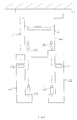
- Figure 1 illustrates, schematically, the arrangement of the different modules component of a circuit breaker according to the invention.
- Figure 2 shows the electrical and optical connections between the different modules of the circuit breaker according to figure 1.
- Figure 3 illustrates, in exploded form, the positioning of the different modules in a particular embodiment.
- FIG. 4 represents, in the form of a block diagram, a particular embodiment of the circuit breaker communication module according to Figures 1 to 3.
- Figures 5 and 6 show a variant of an embodiment of the connection mechanical between the circuit breaker block and the communication module, respectively breaker opening and closing position.
- Figures 7 and 8 illustrate, respectively in perspective and in exploded top view, a particular embodiment of an interface, a calibration module and a module additional of a circuit breaker according to the invention.
- FIG. 9 represents, in the form of a block diagram, the interactions between the module of processing, the calibration module and the additional module of a particular mode of realization of a circuit breaker according to the invention.
- the circuit breaker comprises a block circuit breaker 1, a processing module 2, a calibration module 3 and a communication 4.
- FIG. 2 only the parts of the circuit breaker block essential for understanding the invention have been shown.
- the conductors L1, L2, L3 to be protected cross the circuit breaker block and can be interrupted by breaking contacts 5.
- Current sensors 6 are arranged on each conductor.
- a reel of trigger 7 controls the opening of contacts 5.
- Processing module 2 is electrically connected to the circuit breaker block 1 which supplies it, at the output of the current 6, signals representative of the currents flowing through the conductors L1, L2 and L3.
- the circuit breaker unit can also include voltage sensors 8 so as to supply module 2 with the values of the voltages between conductors L1, L2 and L3.
- the coil trigger 7 causes the opening of contacts 5 when it receives signals from triggering of the processing module 2.
- Additional electrical connectors shown schematically at 9 and 10 in FIG. 2 and arranged respectively on the circuit breaker block and on the processing module, provide these electrical connections when the processing module treatment is mechanically connected to the circuit breaker block.
- the calibration module 3 is mechanically connected to the circuit breaker block by any means of suitable fixing shown diagrammatically in FIG. 1 by a fixing pin A1.
- the module calibration does not have an electrical connection with circuit breaker block 1. However, it is electrically connected ( Figure 2) to the processing module 2, so as to provide this information representative of the rating of the circuit breaker.
- the communication module 4 is mechanically fixed to the circuit breaker block 1 by any suitable fixing means, shown diagrammatically in FIG. 1 by a fixing pin A2. It is physically completely independent of the other modules and is not connected to the treatment 2 only by optical coupling. It is bidirectional and has additional transmitter / receiver optical elements 11 in each of the modules 2 and 4.
- the communication module 4 is connected to an external communication bus 12, bidirectional. It can also be electrically connected, by an electrical link 13, auxiliaries 14 for controlling the circuit breaker. Conventionally, such auxiliaries, constituted for example by opening and / or closing coils of the circuit breaker, are arranged on the circuit breaker block 1. This direct electrical connection between the module communication and the auxiliaries ensures control of the circuit breaker, by via bus 12, communication module 4, electrical connection 13 and auxiliaries 14, even in the absence of the processing module 2.
- the communication module 4 is connected by connection means mechanical, which will be described in more detail with reference to FIGS. 5 and 6, to organs of the circuit breaker block 1 which are representative of the state of the circuit breaker.
- the block of communication 4 can thus carry out functions for signaling the state of the circuit breaker, independently, even in the absence of the processing module.
- the relative positioning of the different modules is illustrated schematically on the Figure 1, and exploded, in the particular embodiment of Figure 3.
- the communication module 4 is disposed between a face 16 of the circuit breaker block and the face rear 17 of a part 18 of lesser thickness of the processing module 2.
- the positioning of the optical link between the transceivers 11 complementary to the communication 4 and processing 2 modules is provided by guide means 19 and 20 provided respectively on the treatment and communication.
- the front face 21 of the processing module 2 constitutes the visible face of the trigger when it is mounted on the circuit breaker block.
- the treatment module rests by its part lower 22, wider, on a base. In a preferred embodiment ( Figures 3 and 7), this consists of an interface 23 to which the module is fixed 3 and the additional module 15.
- the base generally in the form of a square, comprises a first substantially flat part, on which the lower face 24 rests of the processing module, and a second part, perpendicular to the first, intended for be fixed (fixing lugs 26) to the face 16 of the circuit breaker block.
- the second part of the base includes connectors 25 and 9 intended to cooperate with connectors correspondents of the processing module 2, so as to make the electrical connections required between the processing module 2 and the calibration module 3, the module 15 or the circuit breaker block 1 via the interface 23.
- the electrical connectors (9, 25) connecting the processing module 2 to the base and the guide means 19, 20, also constitute means for mechanically fixing the processing module 2 on the circuit breaker block when the interface 23 and the communication 4 are attached to it.
- additional fixing means can be provided.
- FIG 3 such means are shown schematically by a fixing lug 27.
- the electrical connection of the module communication to the bus 12 and to the auxiliaries 14 by the conductor 13 is carried out by means a connector 28 located at the top of the module 4.
- the communication module 4 of FIG. 4 is adapted to a bus 12 of predetermined type. It comprises a line interface 29, connected to the bus 12 and a control circuit 30, connected by a bidirectional link to the line interface 29, both suitable for a bus of predetermined type.
- the other components of the communication module are standard and only circuit 30 and interface 29 must be adapted to the type of bus chosen.
- the bus can be of the BatiBUS, FIP, JBUS type, etc.
- the module 4 includes a control circuit 31 connected, by the link bidirectional optic, to the processing module and constituting an interface for communication with the processing unit.
- the optical transceiver 11 of module 4 belongs to control circuit 31.
- Control circuits 30 and 31 are both connected, by bidirectional links, to a random access memory 32 (RAM), which is thus shared between the communication module and the processing module.
- RAM random access memory
- the communication module 4 is also connected to organs of the circuit breaker block 1 which are representative of the state of the circuit breaker. This mechanical connection (see Figures 5 and 6) is shown at 33 in Figure 4. It actuates a circuit 34 of signaling of the state of the circuit breaker and an operation counter 35. These two circuits, 34 and 35, are connected to the control circuit 30, thus allowing the transfer of these directions on bus 12.
- the communication module 4 further comprises a circuit 36 for controlling the circuit breaker, comprising an input, connected to an output of the control circuit 30, and an output connected by the conductor 13 to the auxiliaries 14 and allowing the control to distance from the circuit breaker.
- the communication module 4 can thus fulfill three independent functions, namely signaling functions (33, 34, 35, 30, 29, 12), circuit breaker control (12, 29, 30, 36, 13) and telemetry and remote control (11, 31, 32, 30, 29, 12).
- This structure of Communication module ensures the independence of the various functions. So the circuit breaker signaling and control functions are provided by the communication even in the absence of the processing unit.
- the communication module is standard for most of its constituents, but adapted, by circuits 29 and 30, to bus type 12 to which the customer wishes to connect the circuit breaker.
- the transformation, in the communication module 4, via circuits 29 and 30, of the protocol adapted to bus 12 in one standardized protocol and vice versa allows the adaptation of the circuit breaker to the different bus types, without increasing the variety of processing modules. This adaptation can be carried out by the end customer who can fix the communication module on the block himself circuit breaker.
- FIG. 5 A particular embodiment of the mechanical connection 33 is shown in Figures 5 and 6.
- the mechanical connection is made by means of microswitches 37, of which only one is shown in section in the figures in the form of a push button mounted on a printed circuit board 38.
- the position not pressed microswitch 37 (fig. 5) is representative of the open state of the breaker breaker, while its pressed position (fig 6) is representative of their state closed.
- the pole shaft 39 of the circuit breaker, linked to the breaking contacts 5, actuates, by via links 40, with return spring, microswitches 37.
- a membrane flexible 41 covers the microswitch 37.
- the flexible membrane has a part 42 permanently forming a tight seal, inside the module 4 housing, around the opening formed in the housing of the module 4 for the passage of the membrane 41.
- the flexible membrane transmits the movement of the rods 40 to the microswitch 37 while maintaining the seal inside the communication module, so as to avoid the entry into module 4 of breaking gases, pollutants, coming from the block circuit breaker 1.
- the force generated by the link system on the microswitches can be measured.
- Others microswitches controlled in a similar way from the circuit breaker block by a system of rods with return springs, allow to signal different mechanical states of the circuit breaker. It is thus possible not only to report the open / closed states of the circuit breaker, but also the armed / disarmed states of the circuit breaker, the fact that the opening has was caused by a fault detected by the processing module, or the state of a locking. All these mechanical states of the circuit breaker are thus transmitted, independently, to the communication module 4, where they are transformed into signals electric and can be signaled either locally or remotely by bus 12.
- a preferred embodiment of the base, comprising the interface 23, the module calibration 3 and the additional module 15, is shown in Figures 7 and 8.
- the module calibration 3 is removably mounted on the base.
- the module 3 and the interface 23 have complementary guide members. preferably also include keying means.
- the organs of guide consist of a guide pin 43, integral with the calibration module, and a complementary guide orifice 44 of the interface 23.
- the fixing of the module calibration can be done by any means allowing easy assembly and disassembly and accessible by the customer after dismantling the treatment module. Such means of fixing may consist of screws and are shown diagrammatically in FIGS. 7 and 8 by the fixing axis A1.
- the additional module 15 also includes guide members complementary to corresponding interface guide members and formed on the Figure 8 by a guide pin 45 complementary to a guide hole 46 of the interface.
- the mounting of the additional module 15 on the interface 23 is carried out in the factory.
- the additional module must not be removable by the customer and the fixing means should be chosen accordingly.
- the additional module is fixed at the interface, and consequently to the circuit breaker block, by clipping. Such fixing allows possibly a disassembly in the factory if necessary.
- FIG. 9 represents their interactions with the module of processing 1. Only the elements of processing module 2 necessary for understanding of these interactions are represented in FIG. 9.
- the current sensors 6 represented in FIG. 2 are constituted by Rogowski toroids providing signals representative of the derivative of the currents with respect to time. These signals are integrated into module 2 by an integration circuit 47, which can be type RC, the output signals of which are representative of the currents in the conductors protect.
- the output of the integration circuit is connected in series to a multiplexer 48, a amplifier 49, an analog / digital converter 50 and a processing circuit microprocessor 51.
- the module calibration 3 avoids the differentiation of the processing module 1 according to the circuit breaker rating.
- the calibration module 3 allows the gain of amplifier 49 depending on the rating chosen by the customer.
- the processing module takes then automatically takes into account the caliber chosen when performing the functions of protection and / or measurement.
- the calibration module 3 includes a resistor R1 which is connected between ground and a input G for gain control of amplifier 49. Input G is connected to voltage V1 via an R2 resistor.
- Resistors R1 and R2 thus form a bridge divider and the value of the resistance R1 of the calibration module fixes the value of the gain of amplifier G, representative of the rating of the circuit breaker.
- the calibration module 3 has a front face 54 with indications representative of the circuit breaker rating (In). These indications remain visible on the front panel when the module is mounted on the interface 23.
- a caliber change is possible by the customer. You just have to dismantle the processing module 2 and replace the old one. calibration module with a new one having the desired caliber. This new caliber, visible in front panel, will be automatically taken into account by the processing module when it will have been replaced.
- the additional module 15 is intended to supply the processing module with the threshold level maximum analog instantaneous, or ultimate instantaneous protection level, of the circuit breaker.
- This level is independent of the type of processing module and the rating of the circuit breaker. he depends on the type of circuit breaker only so as to adapt to the withstand circuit breaker electrodynamics.
- This level linked to the circuit breaker is, for example, fixed by resistors R3, R4 arranged in the additional module.
- Figure 9 provides a better understanding of the role of the additional module 15.
- the outputs of the integration circuit 47 are connected to a rectification 55.
- An analog circuit, ensuring the instantaneous tripping function essentially comprises a comparison circuit 56. This compares a value of threshold S and a signal I, supplied by the rectifying circuit 55 and representative of the current maximum traversing the conductors to be protected.
- the microprocessor 51 detects a fault in the conductors to be protected, it provides a trigger signal. In the event of an instant fault, the fault is detected by the comparison 56 of the analog circuit which produces a trigger signal.
- the signals trigger whether they come from microprocessor 51 or circuit 56, are applied, via an OR circuit 57, to the control electrode of a electronic switch. In FIG. 9, this consists of a thyristor T whose trigger is connected to the output of the OR circuit 57. Its source is connected to ground and its drain is connected, in series with a polarized or reverse diode D, to the voltage V2.
- the drain of thyristor T and voltage V2 are connected to output terminals 58 of the processing connected to the circuit breaker block so as to control the coil trigger 7.
- the threshold S is obtained by a voltage divider, constituted in FIG. 9, by two resistors R5 and R6 arranged in series between voltage V1 and earth. Resistors R3 and R4 of the additional module 15 are connected in parallel on the resistor R5, defining thus the threshold S. This threshold can easily be modified. By eliminating one of the resistors R3 or R4, the threshold S decreases. With two resistors in an additional module, it is easy get four different threshold values.
- the calibration module and the additional module are not limited to the modes particular embodiments of FIG. 9. It is in particular possible to provide a more large number of resistors, so as to increase the number of intermediate thresholds or possible gain values. It is also possible to put two or more resistors in series and not in parallel in a module and shorting the resistors desired.
- the additional module 15 has a front face 59 with indications representative of the breaking capacity of the circuit breaker.
- This power to break representative of the ultimate instantaneous threshold, is generally expressed by a code.
- the normal breaking capacity is represented by the letter N.
- a reinforced breaking capacity can be represented by the letter H and a breaking capacity cut very high by the letter L.
- the calibration module 3 and the additional module 15 are arranged symmetrically with respect to the interface 23.
- the link described above between the communication module 4 and the processing module 2 is an optical link.
- the invention is not limited to this type of connection and extends to any type of galvanically isolated connection, in particular to a connection of the type inductive.
Landscapes
- Breakers (AREA)
- Remote Monitoring And Control Of Power-Distribution Networks (AREA)
- Emergency Protection Circuit Devices (AREA)
- Driving Mechanisms And Operating Circuits Of Arc-Extinguishing High-Tension Switches (AREA)
- Small-Scale Networks (AREA)
- Operating, Guiding And Securing Of Roll- Type Closing Members (AREA)
Abstract
Description
L'invention concerne un disjoncteur comportant un bloc disjoncteur, un module amovible de traitement, comportant une unité de traitement électronique et connecté mécaniquement et électriquement au bloc disjoncteur, un module amovible de calibrage, comportant des moyens de calibrage, fixé mécaniquement au bloc disjoncteur et connecté électriquement à l'unité de traitement, et des moyens de communication connectés à un bus de communication externe.The invention relates to a circuit breaker comprising a circuit breaker block, a removable module processing, comprising an electronic processing unit and mechanically connected and electrically to the circuit breaker block, a removable calibration module, comprising calibration means, mechanically fixed to the circuit breaker block and electrically connected to the processing unit, and communication means connected to a bus external communication.
Il est connu d'utiliser un disjoncteur avec différents types de déclencheurs électroniques. Ceux-ci sont donc généralement amovibles et ne sont montés dans le disjoncteur que lors de l'installation de celui-ci.It is known to use a circuit breaker with different types of electronic trip devices. These are therefore generally removable and are only fitted in the circuit breaker when installing it.
L'invention a pour but d'améliorer l'interchangeabilité des déclencheurs de manière à satisfaire la variété de la demande, allant de la protection de base à la centrale de mesure.The invention aims to improve the interchangeability of triggers so as to meet the variety of demand, from basic protection to the datalogger.
Selon l'invention, ce but est atteint par le fait que le disjoncteur comporte au moins un module amovible de communication, distinct des modules de traitement et de calibrage, comportant lesdits moyens de communication, fixé mécaniquement au bloc disjoncteur et connecté à l'unité de traitement par des moyens de liaison à isolement galvanique, de préférence optique, à des organes du bloc disjoncteur représentatifs de l'état du disjoncteur par des moyens de liaison mécanique et au bus de communication externe par des moyens de liaison électrique d'entrée/sortie.According to the invention, this object is achieved by the fact that the circuit breaker comprises at least one removable communication module, separate from the processing and calibration modules, comprising said means of communication, mechanically fixed to the circuit breaker block and connected to the processing unit by galvanically isolated connecting means, optical preference, to circuit breaker block members representative of the state of the circuit breaker by means of mechanical connection and to the external communication bus by means input / output electrical connection.
Le module de communication peut comporter des moyens de signalisation connectés par les moyens de liaison mécanique au bloc disjoncteur, et des moyens de télémesure et/ou de téléréglage connectés par les moyens de liaison optique à l'unité de traitement, les moyens de signalisation, de télémesure et/ou de téléréglage étant connectés au bus de communication externe par les moyens de liaison électrique d'entrée / sortie. The communication module may include signaling means connected by the mechanical connection means to the circuit breaker block, and telemetry and / or remote control connected by the optical link means to the processing unit, the means signaling, telemetry and / or remote control connected to the bus external communication by means of electrical input / output link.
Il est aussi possible que le module de communication comporte des moyens de commande connectés électriquement à des auxiliaires de commande du disjoncteur, les moyens de commande étant connectés au bus de communication externe par les moyens de liaison électrique d'entrée/sortie.It is also possible that the communication module includes control means. electrically connected to circuit breaker control auxiliaries, the means of control being connected to the external communication bus by the connecting means electrical input / output.
Selon un perfectionnement de l'invention, les moyens de liaison électrique d'entrée/sortie comportent dans le module de communication des moyens adaptés à un bus de communication de type prédéterminé.According to an improvement of the invention, the means of electrical input / output connection include in the communication module means suitable for a bus communication of predetermined type.
Selon un autre perfectionnement, les moyens de liaison mécanique du module de communication aux organes du bloc disjoncteur représentatifs de l'état du disjoncteur comportent des microcontacts, disposés dans le module de communication et ayant des organes de commande en saillie sur une face du module de communication opposée au bloc disjoncteur, et dans le bloc disjoncteur des moyens mécaniques d'actionnement desdits organes de commande, le module de communication comportant des moyens de transformation des signaux mécaniques des microcontacts en signaux électriques et des moyens de signalisation de l'état du disjoncteur. Les organes de commande des microcontacts comportent, de préférence, chacun une membrane, étanche, souple, recouvrant le micro-contact correspondant.According to another improvement, the mechanical connection means of the module communication to the organs of the circuit breaker block representative of the state of the circuit breaker have microswitches, arranged in the communication module and having control elements projecting from one face of the communication module opposite the block circuit breaker, and in the circuit breaker block mechanical means for actuating said circuit breakers control elements, the communication module comprising means for transformation of mechanical signals from microswitches into electrical signals and means for signaling the state of the circuit breaker. The control bodies of microswitches each preferably have a waterproof, flexible membrane, covering the corresponding micro-contact.
La disposition des fonctions de communication dans un module de communication distinct des modules de traitement et de calibrage permet d'adapter le disjoncteur à différents protocoles de communication sans multiplier la variété des modules de traitement. De plus, l'indépendance du module de communication et sa connexion directe, par une liaison mécanique, à des organes du bloc disjoncteur représentatifs de l'état du disjoncteur permettent au module de communication d'assurer certaines fonctions notamment de signalisation, de façon autonome dès qu'il est connecté physiquement au bloc disjoncteur, même en l'absence de module de traitement.The arrangement of communication functions in a separate communication module processing and calibration modules make it possible to adapt the circuit breaker to different communication protocols without increasing the variety of processing modules. Moreover, the independence of the communication module and its direct connection, via a link mechanical, to organs of the circuit breaker block representative of the state of the circuit breaker allow the communication module to perform certain functions including signaling, autonomously as soon as it is physically connected to the circuit breaker block, even in the absence of a processing module.
Selon un perfectionnement de l'invention, le bloc disjoncteur comportant des moyens de mesure de courant constitués par des tores de Rogowski dont la sortie est connectée au module de traitement, le module de calibrage, monté de manière amovible sur le bloc disjoncteur, comporte une face avant avec des indications représentatives du calibre du disjoncteur.According to an improvement of the invention, the circuit breaker block comprising means for current measurement constituted by Rogowski toroids whose output is connected to the processing module, the calibration module, removably mounted on the block circuit breaker, has a front panel with indications representative of the rating of the circuit breaker.
Par ailleurs, le module de traitement comportant des moyens de protection instantanée analogique ultime connectés à des capteurs de courant du bloc disjoncteur et destinés à comparer à un seuil instantané analogique maximal une valeur représentative du courant fournie par les capteurs de courant, le disjoncteur peut comporter un module additionnel comportant des moyens de réglage dudit seuil en fonction du type du disjoncteur, ledit module additionnel étant fixé mécaniquement sur le bloc disjoncteur, de manière non amovible, connecté électriquement au module de traitement et comportant une face comportant des indications représentatives du pouvoir de coupure du disjoncteur.Furthermore, the processing module comprising instant protection means ultimate analog connected to circuit breaker block current sensors and intended for compare a value representative of the current to a maximum instantaneous analog threshold supplied by current sensors, the circuit breaker may include an additional module comprising means for adjusting said threshold as a function of the type of circuit breaker, said additional module being mechanically fixed on the circuit breaker block, so removable, electrically connected to the treatment module and having one face with indications representative of the breaking capacity of the circuit breaker.
Selon une variante, le disjoncteur comporte des moyens de montage du module de calibrage et du module additionnel, lesdits moyens de montage comportant une interface solidaire du bloc disjoncteur et comportant des moyens de guidage et des moyens de fixation complémentaires de moyens de guidage et de moyens de fixation du module de calibrage et du module additionnel.Alternatively, the circuit breaker includes means for mounting the calibration module and the additional module, said mounting means comprising an interface integral with the circuit breaker block and comprising guide means and fixing means complementary to guide means and means for fixing the calibration module and of the additional module.
D'autres avantages et caractéristiques ressortiront plus clairement de la description suivante des différents modes de réalisation, donnés à titre d'exemples non limitatifs et représentés par les dessins annexés dans lesquels :Other advantages and characteristics will emerge more clearly from the following description different embodiments, given by way of nonlimiting examples and represented by the appended drawings in which:
La figure 1 illustre, de manière schématique, la disposition des différents modules composant un disjoncteur selon l'invention.Figure 1 illustrates, schematically, the arrangement of the different modules component of a circuit breaker according to the invention.
La figure 2 représente les liaisons électriques et optiques entre les différents modules du disjoncteur selon la figure 1.Figure 2 shows the electrical and optical connections between the different modules of the circuit breaker according to figure 1.
La figure 3 illustre, sous forme éclatée, le positionnement des différents modules dans un mode de réalisation particulier. Figure 3 illustrates, in exploded form, the positioning of the different modules in a particular embodiment.
La figure 4 représente, sous forme de schéma bloc, un mode particulier de réalisation du module de communication du disjoncteur selon les figures 1 à 3.FIG. 4 represents, in the form of a block diagram, a particular embodiment of the circuit breaker communication module according to Figures 1 to 3.
Les figures 5 et 6 représentent une variante d'un détail de réalisation de la liaison mécanique entre le bloc disjoncteur et le module de communication, respectivement en position d'ouverture et de fermeture du disjoncteur.Figures 5 and 6 show a variant of an embodiment of the connection mechanical between the circuit breaker block and the communication module, respectively breaker opening and closing position.
Les figures 7 et 8 illustrent, respectivement en perspective et en vue de dessus éclatée, un mode de réalisation particulier d'une interface, d'un module de calibrage et d'un module additionnel d'un disjoncteur selon l'invention.Figures 7 and 8 illustrate, respectively in perspective and in exploded top view, a particular embodiment of an interface, a calibration module and a module additional of a circuit breaker according to the invention.
La figure 9 représente, sous forme de schéma bloc, les interactions entre le module de traitement, le module de calibrage et le module additionnel d'un mode particulier de réalisation d'un disjoncteur selon l'invention.FIG. 9 represents, in the form of a block diagram, the interactions between the module of processing, the calibration module and the additional module of a particular mode of realization of a circuit breaker according to the invention.
Comme représenté sur les figures 1 et 2, le disjoncteur selon l'invention comporte un bloc
disjoncteur 1, un module de traitement 2, un module de calibrage 3 et un module de
communication 4.As shown in Figures 1 and 2, the circuit breaker according to the invention comprises a block
circuit breaker 1, a
Sur la figure 2, seules les parties du bloc disjoncteur indispensables à la compréhension de
l'invention ont été représentées. De manière connue, les conducteurs L1, L2, L3 à protéger
traversent le bloc disjoncteur et peuvent être interrompus par des contacts de coupure 5.
Des capteurs de courant 6 sont disposés sur chaque conducteur. Une bobine de
déclenchement 7 commande l'ouverture des contacts 5. Le module de traitement 2 est
connecté électriquement au bloc disjoncteur 1 qui lui fournit, à la sortie des capteurs de
courant 6, des signaux représentatifs des courants parcourant les conducteurs L1, L2 et L3.
Le bloc disjoncteur peut également comporter des capteurs de tension 8 de manière à
fournir au module 2 les valeurs des tensions entre les conducteurs L1, L2 et L3. La bobine
de déclenchement 7 provoque l'ouverture des contacts 5 lorsqu'elle reçoit des signaux de
déclenchement du module de traitement 2. Des connecteurs électriques complémentaires,
schématisés en 9 et 10 sur la figure 2 et disposés respectivement sur le bloc disjoncteur et
sur le module de traitement, assurent ces connexions électriques lorsque le module de
traitement est connecté mécaniquement au bloc disjoncteur.In FIG. 2, only the parts of the circuit breaker block essential for understanding
the invention have been shown. In known manner, the conductors L1, L2, L3 to be protected
cross the circuit breaker block and can be interrupted by breaking
Le module de calibrage 3 est connecté mécaniquement au bloc disjoncteur par tout moyen
de fixation approprié schématisé sur la figure 1 par un axe de fixation A1. Le module de
calibrage ne comporte pas de connexion électrique avec le bloc disjoncteur 1. Par contre, il
est connecté électriquement (figure 2) au module de traitement 2, de manière à fournir à
celui-ci des informations représentatives du calibre du disjoncteur.The
Le module de communication 4 est fixé mécaniquement au bloc disjoncteur 1 par tout
moyen de fixation approprié, schématisé sur la figure 1 par un axe de fixation A2. Il est
physiquement totalement indépendant des autres modules et n'est relié au module de
traitement 2 que par un couplage optique. Celui-ci est bidirectionnel et comporte des
éléments optiques émetteurs/récepteurs 11 complémentaires dans chacun des modules 2
et 4. Le module de communication 4 est connecté à un bus de communication externe 12,
bidirectionnel. Il peut également être connecté électriquement, par une liaison électrique 13,
à des auxiliaires 14 de commande du disjoncteur. De manière classique, de tels auxiliaires,
constitués par exemple par des bobines d'ouverture et/ou de fermeture du disjoncteur, sont
disposés sur le bloc disjoncteur 1. Cette connexion électrique directe entre le module de
communication et les auxiliaires permet d'assurer la commande du disjoncteur, par
l'intermédiaire du bus 12, du module de communication 4, de la liaison électrique 13 et des
auxiliaires 14, même en l'absence du module de traitement 2.The
Par ailleurs, le module de communication 4 est connecté par des moyens de liaison
mécanique, qui seront décrits plus en détail en regard des figures 5 et 6, à des organes du
bloc disjoncteur 1 qui sont représentatifs de l'état du disjoncteur. Le bloc de
communication 4 peut ainsi réaliser des fonctions de signalisation de l'état du disjoncteur,
de façon autonome, même en l'absence du module de traitement.Furthermore, the
Un module additionnel 15, physiquement solidaire du bloc disjoncteur 1 est représenté à la
figure 2. Sa nature et sa fonction seront décrites plus en détail au regard des figures 7 à 9. An
Le positionnement relatif des différents modules est illustré de manière schématique sur la
figure 1, et de façon éclatée, dans le mode de réalisation particulier de la figure 3. Le
module de communication 4 est disposé entre une face 16 du bloc disjoncteur et la face
arrière 17 d'une partie 18 de moindre épaisseur du module de traitement 2. Le
positionnement de la liaison optique entre les émetteurs-récepteurs 11 complémentaires des
modules de communication 4 et de traitement 2 est assuré par des moyens de guidage
complémentaires 19 et 20 prévus respectivement sur les modules de traitement et de
communication.The relative positioning of the different modules is illustrated schematically on the
Figure 1, and exploded, in the particular embodiment of Figure 3. The
La face avant 21 du module de traitement 2 constitue la face visible du déclencheur lorsqu'il
est monté sur le bloc disjoncteur. Le module de traitement repose par sa partie
inférieure 22, plus large, sur une embase. Dans un mode de réalisation préférentiel
(figures 3 et 7), celle-ci est constituée par une interface 23 à laquelle sont fixés le module
de calibrage 3 et le module additionnel 15. L'embase, en forme générale d'équerre,
comporte une première partie sensiblement plane, sur laquelle repose la face inférieure 24
du module de traitement, et une seconde partie, perpendiculaire à la première, destinée à
être fixée (pattes de fixation 26) à la face 16 du bloc disjoncteur. La seconde partie de
l'embase comporte des connecteurs 25 et 9 destinés à coopérer avec des connecteurs
correspondants du module de traitement 2, de manière à réaliser les connexions électriques
nécessaires entre le module de traitement 2 et le module de calibrage 3, le module
additionnel 15 ou le bloc disjoncteur 1 par l'intermédiaire de l'interface 23.The
Les connecteurs électriques (9, 25) reliant le module de traitement 2 à l'embase et les
moyens de guidage 19, 20, constituent également des moyens de fixation mécanique du
module de traitement 2 sur le bloc disjoncteur lorsque l'interface 23 et le module de
communication 4 sont fixés à celui-ci. Pour assurer une bonne stabilité mécanique des
moyens additionnels de fixation peuvent être prévus. Sur la figure 3 de tels moyens sont
schématisés par une patte de fixation 27. The electrical connectors (9, 25) connecting the
Dans le mode de réalisation particulier de la figure 3, la connexion électrique du module de
communication au bus 12 et aux auxiliaires 14 par le conducteur 13 est réalisée au moyen
d'un connecteur 28 situé à la partie supérieure du module 4.In the particular embodiment of Figure 3, the electrical connection of the module
communication to the
Le module de communication 4 de la figure 4 est adapté à un bus 12 de type prédéterminé.
Il comporte une interface de ligne 29, connectée au bus 12 et un circuit de commande 30,
connecté par une liaison bidirectionnelle à l'interface de ligne 29, tous deux adaptés à un
bus de type prédéterminé. Les autres composants du module de communication sont
standards et seuls le circuit 30 et l'interface 29 doivent être adaptés au type de bus choisi.
A titre d'exemples non limitatifs le bus peut être du type BatiBUS, FIP, JBUS, etc...The
Par ailleurs, le module 4 comporte un circuit de commande 31 connecté, par la liaison
optique bidirectionnelle, au module de traitement et constituant une interface de
communication avec l'unité de traitement. L'émetteur-récepteur optique 11 du module 4
appartient au circuit de commande 31. Les circuits de commande 30 et 31 sont tous deux
connectés, par des liaisons bidirectionnelles, à une mémoire vive 32 (RAM), qui est ainsi
partagée entre le module de communication et le module de traitement. On obtient ainsi,
par l'intermédiaire du module de communication 4 et de la liaison optique, une
communication entre le bus 12 et le module de traitement 2. Il est ainsi possible de lire et
d'écrire des données dans le module de traitement et de réaliser des fonctions de télémesure
(du module de traitement vers le bus), de téléréglage (du bus vers le module de traitement),
d'indication des causes d'un déclenchement (du module de traitement vers le bus), etc...Furthermore, the
Le module de communication 4 est également connecté à des organes du bloc disjoncteur 1
qui sont représentatifs de l'état du disjoncteur. Cette liaison, de type mécanique (voir
figures 5 et 6) est représentée en 33 à la figure 4. Elle permet d'actionner un circuit 34 de
signalisation de l'état du disjoncteur et un compteur de manoeuvres 35. Ces deux circuits,
34 et 35, sont connectés au circuit de commande 30, permettant ainsi le transfert de ces
indications sur le bus 12. The
Le module de communication 4 comporte, de plus, un circuit 36 de commande du
disjoncteur, comportant une entrée, connectée à une sortie du circuit de commande 30, et
une sortie connectée par le conducteur 13 aux auxiliaires 14 et permettant la commande à
distance du disjoncteur.The
Le module de communication 4 peut ainsi remplir trois fonctions indépendantes, à savoir
des fonctions de signalisation (33, 34, 35, 30, 29, 12), de commande du disjoncteur (12,
29, 30, 36, 13) et de télémesure et téléréglage (11, 31, 32, 30, 29, 12). Cette structure du
module de communication assure l'indépendance des différentes fonctions. Ainsi, les
fonctions de signalisation et de commande du disjoncteur sont assurées par le module de
communication même en l'absence de l'unité de traitement. Le module de communication
est standard pour l'essentiel de ses constituants, mais adapté, par les circuits 29 et 30, au
type de bus 12 auquel le client désire connecter le disjoncteur. La transformation, dans le
module de communication 4, par les circuits 29 et 30, du protocole adapté au bus 12 en un
protocole standardisé et réciproquement permet l'adaptation du disjoncteur aux différents
types de bus, sans multiplier la variété des modules de traitement. Cette adaptation peut être
réalisée par le client final qui peut fixer lui-même le module de communication sur le bloc
disjoncteur.The
Un mode de réalisation particulier de la liaison mécanique 33 est représenté aux figures 5
et 6. La liaison mécanique s'effectue par l'intermédiaire de microcontacts 37, dont un seul
est représenté, en coupe, sur les figures sous la forme d'un bouton-poussoir monté sur une
carte 38 de circuit imprimé. Dans le module de communication 4 représenté, la position
non appuyée du microcontact 37 (fig. 5) est représentative de l'état ouvert des contacts de
coupure du disjoncteur, tandis que sa position appuyée (fig 6) est représentative de leur état
fermé. L'arbre des pôles 39 du disjoncteur, lié aux contacts de coupure 5, actionne, par
l'intermédiaire de biellettes 40, avec ressort de rappel, les microcontacts 37. Une membrane
souple 41 encapuchonne le microcontact 37. La membrane souple comporte une partie 42
formant en permanence un joint étanche, à l'intérieur du boítier du module 4, autour de
l'ouverture formée dans le boítier du module 4 pour le passage de la membrane 41. La
membrane souple transmet le mouvement des biellettes 40 au microcontact 37 tout en
maintenant l'étanchéité à l'intérieur du module de communication, de manière à éviter
l'entrée dans le module 4 de gaz de coupure, polluants, en provenance du bloc
disjoncteur 1.A particular embodiment of the
L'effort engendré par le système de biellettes sur les microcontacts peut être dosé. D'autres
microcontacts, commandés de manière analogue à partir du bloc disjoncteur par un système
de biellettes avec ressorts de rappel, permettent de signaler différents états mécaniques du
disjoncteur. Il est ainsi possible non seulement de signaler les états ouvert/fermé du
disjoncteur, mais également les états armé/désarmé du disjoncteur, le fait que l'ouverture a
été provoquée par un défaut détecté par le module de traitement, ou l'état d'un organe de
verrouillage. Tous ces états mécaniques du disjoncteur sont ainsi transmis,
indépendamment, au module de communication 4, où ils sont transformés en signaux
électriques et peuvent être signalés soit localement, soit à distance par le bus 12.The force generated by the link system on the microswitches can be measured. Others
microswitches, controlled in a similar way from the circuit breaker block by a system
of rods with return springs, allow to signal different mechanical states of the
circuit breaker. It is thus possible not only to report the open / closed states of the
circuit breaker, but also the armed / disarmed states of the circuit breaker, the fact that the opening has
was caused by a fault detected by the processing module, or the state of a
locking. All these mechanical states of the circuit breaker are thus transmitted,
independently, to the
L'utilisation d'une liaison mécanique 33 entre le bloc disjoncteur et le module de
communication pour effectuer les fonctions de signalisation permet en outre, de limiter la
filerie indépendante du module de traitement.The use of a
Un mode de réalisation préférentiel de l'embase, comportant l'interface 23, le module de
calibrage 3 et le module additionnel 15, est représenté aux figures 7 et 8. Le module de
calibrage 3 est monté de manière amovible sur l'embase. Pour faciliter le montage, le
module 3 et l'interface 23 comportent des organes de guidage complémentaires.Ils
comportent aussi, de préférence, des moyens de détrompage. Sur la figure 8, les organes de
guidage sont constitués par une broche de guidage 43, solidaire du module de calibrage, et
un orifice de guidage complémentaire 44 de l'interface 23. La fixation du module de
calibrage peut se faire par tout moyen permettant un montage et un démontage aisés et
accessibles par le client après démontage du module de traitement. De tels moyens de
fixation peuvent être constitués par des vis et sont schématisés sur les figures 7 et 8 par
l'axe de fixation A1. Le module additionnel 15 comporte également des organes de guidage
complémentaires d'organes de guidage correspondants de l'interface et constitués sur la
figure 8 par une broche de guidage 45 complémentaire d'un orifice de guidage 46 de
l'interface. Le montage du module additionnel 15 sur l'interface 23 est réalisé en usine. Le
module additionnel ne doit pas être démontable par le client et les moyens de fixation
doivent être choisis en conséquence. A titre d'exemple, le module additionnel est fixé à
l'interface, et en conséquence au bloc disjoncteur, par clipsage. Une telle fixation permet
éventuellement un démontage en usine si nécessaire.A preferred embodiment of the base, comprising the
Les fonctions du module de calibrage et du module additionnel vont être explicitées plus en
détail au regard de la figure 9 qui représente leurs interactions avec le module de
traitement 1. Seuls les éléments du module de traitement 2 nécessaires à la compréhension
de ces interactions sont représentés sur la figure 9. Dans ce mode de réalisation, les
capteurs de courant 6 représentés à la figure 2 sont constitués par des tores de Rogowski
fournissant des signaux représentatifs de la dérivée des courants par rapport au temps. Ces
signaux sont intégrés dans le module 2 par un circuit d'intégration 47, qui peut être de
type RC, dont les signaux de sortie sont représentatifs des courants dans les conducteurs à
protéger. La sortie du circuit d'intégration est connectée en série à un multiplexeur 48, un
amplificateur 49, un convertisseur analogique/numérique 50 et un circuit de traitement à
microprocesseur 51. Lorsque les capteurs de courant 6 sont des tores de Rogowski , la
puissance fournie est généralement insuffisante pour alimenter le module de traitement. On
ajoute alors des capteurs de courant 52 à noyau fer, dans le bloc disjoncteur, connectés à un
circuit d'alimentation 53 du module de traitement 2 qui fournit notamment des tensions V1
et V2 d'alimentation par rapport à la masse. La tension V1 est destinée à l'alimentation des
circuits électroniques du module 2, tandis que la tension V2, plus élevée, est destinée à
l'alimentation de la bobine de déclenchement en cas de déclenchement.The functions of the calibration module and the additional module will be explained in more detail.
detail with regard to FIG. 9 which represents their interactions with the module of
processing 1. Only the elements of
Lorsque les capteurs de courant sont constitués par des tores de Rogoswki, ceux-ci sont
identiques quel que soit le calibre du disjoncteur. Dans les disjoncteurs connus utilisant ce
type de capteur de courant, le calibre est fixé par le déclencheur. Il est alors nécessaire de
prévoir des déclencheurs différents pour les différents calibres du disjoncteur. Le module de
calibrage 3 permet d'éviter la différenciation du module de traitement 1 en fonction du
calibre du disjoncteur. Le module de calibrage 3 permet de modifier le gain de
l'amplificateur 49 en fonction du calibre choisi par le client. Le module de traitement prend
alors automatiquement en compte le calibre choisi lors de la réalisation des fonctions de
protection et /ou de mesure. Dans le mode de réalisation représenté sur la figure 9, le
module de calibrage 3 comporte une résistance R1 qui est connectée entre la masse et une
entrée G de contrôle de gain de l'amplificateur 49. L'entrée G est connectée à la tension V1
par l'intermédiaire d'une résistance R2. Les résistances R1 et R2 forment ainsi un pont
diviseur et la valeur de la résistance R1 du module de calibrage fixe la valeur du gain de
l'amplificateur G, représentatif du calibre du disjoncteur. Comme représenté à la figure 7,
le module de calibrage 3 comporte une face avant 54 avec des indications représentatives du
calibre (In) du disjoncteur. Ces indications restent visibles en face avant lorsque le module
de traitement est monté sur l'interface 23. Un changement de calibre est possible par le
client. Il suffit pour cela de démonter le module de traitement 2 et de remplacer l'ancien
module de calibrage par un nouveau ayant le calibre désiré. Ce nouveau calibre, visible en
face avant, sera automatiquement pris en compte par le module de traitement lorsque celui-ci
aura été remis en place.When the current sensors consist of Rogoswki toroids, these are
identical regardless of the size of the circuit breaker. In known circuit breakers using this
type of current sensor, the rating is fixed by the trigger. It is then necessary to
provide different trip units for the different ratings of the circuit breaker. The
Le module additionnel 15 est destiné à fournir au module de traitement le niveau du seuil
instantané analogique maximal, ou niveau de protection instantanée ultime, du disjoncteur.
Ce niveau est indépendant du type de module de traitement et du calibre du disjoncteur. Il
est fonction du type de disjoncteur uniquement de manière à s'adapter à la tenue
électrodynamique du disjoncteur. Ce niveau lié au disjoncteur, est, par exemple, fixé par
des résistances R3, R4 disposées dans le module additionnel.The
La figure 9 permet de mieux comprendre le rôle du module additionnel 15. Dans le module
de traitement 2, les sorties du circuit d'intégration 47 sont connectées à un circuit de
redressement 55. Un circuit analogique, assurant la fonction de déclenchement instantané
comporte essentiellement un circuit de comparaison 56. Celui-ci compare une valeur de
seuil S et un signal I, fourni par le circuit de redressement 55 et représentatif du courant
maximum parcourant les conducteurs à protéger.Figure 9 provides a better understanding of the role of the
Si le microprocesseur 51 détecte un défaut dans les conducteurs à protéger, il fournit un
signal de déclenchement. En cas de défaut instantané, le défaut est détecté par le circuit de
comparaison 56 du circuit analogique qui produit un signal de déclenchement. Les signaux
de déclenchement, qu'ils proviennent du microprocesseur 51 ou du circuit 56, sont
appliqués, par l'intermédiaire d'un circuit OU 57, à l'électrode de commande d'un
commutateur électronique. Sur la figure 9, celui-ci est constitué par un thyristor T dont la
gâchette est connectée à la sortie du circuit OU 57. Sa source est connectée à la masse et
son drain est connecté, en série avec une diode D polarisée ou inverse, à la tension V2. Le
drain du thyristor T et la tension V2 sont connectés à des bornes de sortie 58 du module de
traitement connecté au bloc disjoncteur de manière à commander la bobine de
déclenchement 7.If the
Le seuil S est obtenu par un diviseur de tension, constitué sur la figure 9, par deux
résistances R5 et R6 disposées en série entre la tension V1 et la masse. Les résistance R3 et
R4 du module additionnel 15 sont connectées en parallèle sur la résistance R5, définissant
ainsi le seuil S. Ce seuil peut facilement être modifié. En éliminant l'une des résistances R3
ou R4, le seuil S diminue. Avec deux résistances dans un module additionnel, il est facile
d'obtenir quatre valeurs différentes du seuil.The threshold S is obtained by a voltage divider, constituted in FIG. 9, by two
resistors R5 and R6 arranged in series between voltage V1 and earth. Resistors R3 and
R4 of the
Bien entendu, le module de calibrage et le module additionnel ne sont pas limités aux modes de réalisation particuliers de la figure 9. Il est en particulier possible de prévoir un plus grand nombre de résistances, de manière à augmenter le nombre de seuils intermédiaires ou de valeurs de gain possibles. Il est également possible de mettre deux ou plusieurs résistances en série et non en parallèle dans un module et de court-circuiter les résistances désirées.Of course, the calibration module and the additional module are not limited to the modes particular embodiments of FIG. 9. It is in particular possible to provide a more large number of resistors, so as to increase the number of intermediate thresholds or possible gain values. It is also possible to put two or more resistors in series and not in parallel in a module and shorting the resistors desired.
Comme représenté à la figure 7, le module additionnel 15 comporte une face avant 59 avec
des indications représentatives du pouvoir de coupure du disjoncteur. Ce pouvoir de
coupure, représentatif du seuil instantané ultime, est généralement exprimé par un code. A
titre d'exemple, sur la figure 7, le pouvoir de coupure normal est représenté par la lettre N.
Un pouvoir de coupure renforcé peut être représenté par la lettre H et un pouvoir de
coupure très haut par la lettre L. As shown in FIG. 7, the
Sur les figures 7 et 8, le module de calibrage 3 et le module additionnel 15 sont disposés
symétriquement par rapport à l'interface 23.In FIGS. 7 and 8, the
L'utilisation d'un interface 23, liée au bloc disjoncteur, et portant le module additionnel 15
et le module de calibrage 3 permet l'interchangeabilité des modules de traitement.
L'utilisation des modules permet une différenciation tardive des variantes d'un même
disjoncteur, et une adaptation simple aux besoins des clients.The use of an
La liaison décrite ci-dessus entre le module de communication 4 et le module de traitement
2 est une liaison optique. Cependant, l'invention n'est pas limitée à ce type de liaison et
s'étend à tout type de liaison à isolement galvanique, notamment à une liaison de type
inductif.The link described above between the
Claims (12)
Applications Claiming Priority (2)
| Application Number | Priority Date | Filing Date | Title |
|---|---|---|---|
| FR9614171A FR2756095B1 (en) | 1996-11-15 | 1996-11-15 | CIRCUIT BREAKER WITH A CIRCUIT BREAKER AND PROCESSING, CALIBRATION AND COMMUNICATION MODULES |
| FR9614171 | 1996-11-15 |
Publications (2)
| Publication Number | Publication Date |
|---|---|
| EP0843332A1 true EP0843332A1 (en) | 1998-05-20 |
| EP0843332B1 EP0843332B1 (en) | 2005-01-05 |
Family
ID=9497827
Family Applications (1)
| Application Number | Title | Priority Date | Filing Date |
|---|---|---|---|
| EP97410126A Expired - Lifetime EP0843332B1 (en) | 1996-11-15 | 1997-11-06 | Circuit breaker having a breaker block and modules for processing, calibration and indication |
Country Status (28)
| Country | Link |
|---|---|
| US (1) | US5877691A (en) |
| EP (1) | EP0843332B1 (en) |
| JP (1) | JP3768342B2 (en) |
| KR (1) | KR100475219B1 (en) |
| CN (1) | CN1074191C (en) |
| AR (1) | AR008694A1 (en) |
| AT (1) | ATE286621T1 (en) |
| AU (1) | AU729161B2 (en) |
| BR (1) | BR9705721B1 (en) |
| CA (1) | CA2217835C (en) |
| CZ (1) | CZ292580B6 (en) |
| DE (1) | DE69732171T2 (en) |
| EA (1) | EA000997B1 (en) |
| EG (1) | EG21182A (en) |
| ES (1) | ES2236787T3 (en) |
| FR (1) | FR2756095B1 (en) |
| HU (1) | HU222290B1 (en) |
| ID (1) | ID18935A (en) |
| MY (1) | MY117008A (en) |
| NO (1) | NO314737B1 (en) |
| OA (1) | OA10633A (en) |
| PL (1) | PL188958B1 (en) |
| PT (1) | PT843332E (en) |
| SG (1) | SG63768A1 (en) |
| TR (1) | TR199701361A2 (en) |
| TW (1) | TW358253B (en) |
| UA (1) | UA41450C2 (en) |
| ZA (1) | ZA9710185B (en) |
Cited By (19)
| Publication number | Priority date | Publication date | Assignee | Title |
|---|---|---|---|---|
| EP1034590A4 (en) * | 1998-06-23 | 2004-03-17 | Gen Electric | Modular protective relay with submodules |
| WO2007128421A1 (en) * | 2006-05-04 | 2007-11-15 | Moeller Gmbh | Circuit breaker for motor protection and/or line protection |
| CZ300119B6 (en) * | 2006-01-25 | 2009-02-11 | Oez, S. R. O. | Electric apparatus system, particularly of power circuit breaker and additional modules |
| WO2010000394A1 (en) * | 2008-07-02 | 2010-01-07 | Moeller Gmbh | Electric protective switch device having control electronics |
| EP2423933A1 (en) * | 2010-08-30 | 2012-02-29 | Siemens Aktiengesellschaft | Circuit breaker holder module |
| WO2013190001A1 (en) * | 2012-06-22 | 2013-12-27 | Abb Ag | Auxiliary switch |
| FR3007902A1 (en) * | 2013-06-26 | 2015-01-02 | Schneider Electric Ind Sas | REMOVABLE DEVICE FOR ELECTRONIC TRIGGER, METHOD FOR SUPPLYING SUCH A DEVICE, AND ASSEMBLY COMPRISING AN ELECTRONIC TRIGGER AND SUCH A REMOVABLE DEVICE |
| EP2731121A3 (en) * | 2012-11-02 | 2015-11-25 | Rockwell Automation Technologies, Inc. | Modular Overload relay assembly with preformed coil interface |
| FR3026192A1 (en) * | 2014-09-23 | 2016-03-25 | Schneider Electric Ind Sas | METHOD FOR TESTING THE ENTIRE PROTECTIVE CHAIN IN A MEDIUM VOLTAGE ELECTRICAL PROTECTION EQUIPMENT, AND APPARATUS FOR IMPLEMENTING SUCH A METHOD |
| EP3018691A1 (en) | 2014-11-10 | 2016-05-11 | Schneider Electric Industries SAS | Tripping unit for electrical switching device, and electrical switching device comprising such an unit |
| FR3028661A1 (en) * | 2014-11-19 | 2016-05-20 | Schneider Electric Ind Sas | ELECTRIC CIRCUIT BREAKER INCLUDING A TRIGGER BLOCK |
| WO2018109414A1 (en) * | 2016-12-16 | 2018-06-21 | Hager-Electro Sas | Assembly of a switch and an auxiliary unit |
| CN109904040A (en) * | 2019-03-13 | 2019-06-18 | 北京京人电器有限公司 | A kind of buckle releaser and electrical switchgear |
| EP4080539A1 (en) * | 2021-04-23 | 2022-10-26 | Siemens Aktiengesellschaft | Protective switch with overload protection |
| EP4625642A2 (en) | 2024-03-28 | 2025-10-01 | Schneider Electric Industries Sas | Battery module for a control unit of an electrical circuit breaker, associated control unit and electrical circuit breaker |
| EP4625460A1 (en) | 2024-03-28 | 2025-10-01 | Schneider Electric Industries Sas | Control unit for an electric circuit breaker and associated electric circuit breaker |
| EP4625459A1 (en) | 2024-03-28 | 2025-10-01 | Schneider Electric Industries Sas | Control unit for an electric circuit breaker and associated electric circuit breaker |
| EP4625461A1 (en) | 2024-03-28 | 2025-10-01 | Schneider Electric Industries Sas | Control unit for an electric circuit breaker and associated electric circuit breaker |
| EP4625465A1 (en) | 2024-03-28 | 2025-10-01 | Schneider Electric Industries Sas | Control unit for an electrical circuit breaker and associated electrical circuit breaker |
Families Citing this family (63)
| Publication number | Priority date | Publication date | Assignee | Title |
|---|---|---|---|---|
| FR2751501B1 (en) * | 1996-07-16 | 1999-04-30 | Schneider Electric Sa | ELECTRICAL APPARATUS COMPRISING A COMMUNICATION DEVICE |
| US6094044A (en) * | 1998-05-07 | 2000-07-25 | Airpax Corporation, Llc | AC current sensor having high accuracy and large bandwidth |
| US6169651B1 (en) * | 1998-06-05 | 2001-01-02 | General Electric Company | Protective relay with modular control panel |
| NL1011843C2 (en) | 1999-04-20 | 2000-11-06 | Capax B V | Improved power tool switch. |
| DE19927029A1 (en) * | 1999-06-04 | 2001-02-08 | Siemens Ag | Method for operating an electronic overcurrent release of a circuit breaker |
| US6295190B1 (en) * | 1999-10-26 | 2001-09-25 | Electric Boat Corporation | Circuit breaker arrangement with integrated protection, control and monitoring |
| ITBG20030005A1 (en) * | 2003-01-28 | 2004-07-29 | Abb Service Srl | LOW VOLTAGE SWITCH INCLUDING AN INTERFACE UNIT. |
| FR2858133B1 (en) * | 2003-07-25 | 2006-02-03 | Michel Combier | INTELLIGENT ELECTRICAL SWITCHING DEVICE FOR SECURING ELECTRICITY DISTRIBUTION MEANS |
| US6956452B2 (en) | 2003-09-24 | 2005-10-18 | General Electric Company | Apparatus and method for circuit breaker trip unit adjustment |
| US6980071B2 (en) | 2003-09-24 | 2005-12-27 | General Electric Company | Apparatus and method for circuit breaker trip unit adjustment |
| US8355230B2 (en) * | 2003-12-08 | 2013-01-15 | Siemens Industry, Inc. | Extended instantaneous protection |
| GB2411960B8 (en) * | 2004-03-11 | 2006-11-30 | Transense Technologies Plc | Method and apparatus for electronic storing of calibration/identification data for a wirelss linear passive sensor |
| US7324005B2 (en) * | 2004-04-28 | 2008-01-29 | Stoof Ronald M | Modular surge protection |
| AT501217B1 (en) * | 2004-07-21 | 2007-09-15 | Moeller Gebaeudeautomation Kg | SWITCHING DEVICE |
| KR100760331B1 (en) * | 2006-03-30 | 2007-09-20 | 신성산전주식회사 | High speed failure section automatic shut-off device |
| US8116054B2 (en) * | 2006-12-29 | 2012-02-14 | General Electric Company | Universal rating plug for electronic trip unit |
| US7916508B2 (en) * | 2007-12-05 | 2011-03-29 | General Electric Company | Systems and methods involving thyristors |
| US7859384B2 (en) * | 2008-01-29 | 2010-12-28 | Siemens Industry, Inc. | Devices, systems, and methods for managing a circuit breaker |
| US20090257163A1 (en) * | 2008-04-15 | 2009-10-15 | General Electric Company | Current gain control of circuit breaker trip unit |
| DE102008050753A1 (en) * | 2008-10-07 | 2010-04-08 | Siemens Aktiengesellschaft | Method for detecting a physical quantity by a circuit breaker |
| JP5225234B2 (en) * | 2009-08-19 | 2013-07-03 | 三菱電機株式会社 | Electronic protective relay |
| GB2476448B (en) * | 2009-09-17 | 2015-07-15 | Sean Christopher Ganley | An interchangeable add-on device to fit on the front part of a ciruit protection device for bi-directional data transfer and remote set and reset |
| DE102010026246A1 (en) * | 2010-07-01 | 2011-06-22 | Siemens Aktiengesellschaft, 80333 | Multipolar circuit-breaker for low-voltage for interrupting phase stream flowing through conductor by electronic trigger unit, has multiplexer providing voltage to input of amplifier whose output is connected with trigger unit |
| CN102568939A (en) * | 2010-12-15 | 2012-07-11 | 浙江天正电气股份有限公司 | Automatic calibration method of circuit breaker |
| IT1403511B1 (en) * | 2011-02-03 | 2013-10-31 | Abb Spa | ELECTRIC SWITCHING DEVICE. |
| JP5980557B2 (en) * | 2012-04-27 | 2016-08-31 | 河村電器産業株式会社 | Power measuring device |
| US9559513B2 (en) * | 2012-11-02 | 2017-01-31 | Rockwell Automation Technologies, Inc. | Voltage sensor contact for an electronic device |
| CN104733242A (en) * | 2012-12-31 | 2015-06-24 | 胡小青 | Intelligent circuit breaker with communication protocol converter |
| CN104733239B (en) * | 2012-12-31 | 2017-05-24 | 国网安徽省电力公司铜陵供电公司 | Intelligent circuit breaker with communication protocol converter easily disassembled and assembled |
| CN104992881A (en) * | 2012-12-31 | 2015-10-21 | 胡小青 | Intelligent molded case circuit breaker capable of easily positioning communication protocol converter |
| CN103135483A (en) * | 2012-12-31 | 2013-06-05 | 人民电器集团有限公司 | Protocol conversion module and intelligent circuit breaker of Profibus and Modbus |
| CN103135484A (en) * | 2012-12-31 | 2013-06-05 | 人民电器集团有限公司 | Protocol conversion module and intelligent circuit breaker of Devicenet and Modbus |
| CN103021743B (en) * | 2012-12-31 | 2015-12-23 | 国网浙江海宁市供电公司 | smart circuit breaker |
| CN104733238B (en) * | 2012-12-31 | 2016-11-30 | 国网山东省电力公司菏泽供电公司 | A kind of intelligent breaker with Modbus protocol interface socket |
| CN103092111B (en) * | 2012-12-31 | 2017-03-08 | 人民电器集团有限公司 | There is the intelligent breaker of the protocol conversion module of Can and Modbus |
| CN104733244A (en) * | 2012-12-31 | 2015-06-24 | 吴红平 | Intelligent moulded-case circuit breaker |
| CN104733240A (en) * | 2012-12-31 | 2015-06-24 | 胡小青 | Intelligent circuit breaker with detachable communication protocol converter |
| CN104733235B (en) * | 2012-12-31 | 2017-01-18 | 国网山东省电力公司蒙阴县供电公司 | Intelligent circuit breaker with Modbus protocol interface socket |
| CN104979138A (en) * | 2012-12-31 | 2015-10-14 | 苏州君丰辰电子科技有限公司 | Smart molded case circuit breaker with easily detachable communication protocol converter |
| CN104733236B (en) * | 2012-12-31 | 2016-09-14 | 国网山东省电力公司曲阜市供电公司 | A kind of intelligent breaker with detachable communication protocols converter |
| CN103107049A (en) * | 2013-01-01 | 2013-05-15 | 苏州君丰辰电子科技有限公司 | Intelligent plastic-case switch |
| MX352856B (en) | 2013-09-26 | 2017-12-13 | Schneider Electric Usa Inc | Load center monitor with optical waveguide sheet. |
| CA2925222C (en) * | 2013-10-09 | 2023-09-05 | Schneider Electric USA, Inc. | Self-contained branch circuit monitor |
| WO2015080693A1 (en) | 2013-11-26 | 2015-06-04 | Schneider Electric USA, Inc. | Wireless batteryless data processing unit |
| WO2015084387A1 (en) | 2013-12-06 | 2015-06-11 | Schneider Electric USA, Inc. | Temperature sensor for bolted connections |
| WO2015152874A1 (en) | 2014-03-31 | 2015-10-08 | Schneider Electric USA, Inc. | Live load indicator with door interlock |
| GB2530498A (en) * | 2014-09-23 | 2016-03-30 | Martin Bills | A diagnostic and communication device for circuit breakers |
| US9658264B2 (en) | 2014-12-30 | 2017-05-23 | Energybox Ltd. | Energy metering system with self-powered sensors |
| US9995815B2 (en) | 2014-12-30 | 2018-06-12 | Energybox Ltd. | Energy metering system and method for its calibration |
| US10467354B2 (en) | 2014-12-30 | 2019-11-05 | Energybox Ltd. | Visualization of electrical loads |
| US9715796B2 (en) * | 2015-10-13 | 2017-07-25 | Schneider Electric USA, Inc. | Communicating circuit breaker architecture with automatic load center position identification |
| KR20170098062A (en) * | 2016-02-19 | 2017-08-29 | 엘에스산전 주식회사 | Fault detector for anti-parallel thyristor |
| CN106158519A (en) * | 2016-08-29 | 2016-11-23 | 孟玲 | A kind of intelligent moulded case circuit breaker maintenance system |
| FR3055420B1 (en) * | 2016-08-31 | 2018-09-28 | Schneider Electric Industries Sas | CONTROL UNIT OF AN ELECTRIC CIRCUIT BREAKER AND CIRCUIT BREAKER COMPRISING SUCH A CONTROL UNIT |
| BR112020000644A2 (en) * | 2017-07-10 | 2020-07-14 | Berker Gmbh & Co. Kg | electrical equipment and associated additional functional module |
| AU2017423231B2 (en) * | 2017-07-10 | 2021-07-29 | Berker Gmbh & Co. Kg | Electrical equipment and additional functional module associated therewith |
| US11393645B2 (en) * | 2017-07-10 | 2022-07-19 | Berker Gmbh & Co. Kg | Electrical equipment and additional functional module associated therewith |
| US11211786B2 (en) * | 2017-11-08 | 2021-12-28 | Abb Schweiz Ag | Smart module for a circuit breaker |
| EP3633707B1 (en) | 2018-10-04 | 2022-08-24 | ABB S.p.A. | Accessory device for low and medium voltage switching devices |
| US11139131B2 (en) | 2018-12-21 | 2021-10-05 | Abb Schweiz Ag | Electromechanical relay with data collection cover |
| US11271383B2 (en) * | 2019-12-17 | 2022-03-08 | Schneider Electric USA, Inc. | Auto wire-size detection in branch circuit breakers |
| KR102485881B1 (en) * | 2020-05-04 | 2023-01-06 | 엘에스일렉트릭(주) | Solid State Circuit Breaker |
| GB2616890A (en) * | 2022-03-24 | 2023-09-27 | Eaton Intelligent Power Ltd | Improved data interface for a circuit breaker and system with such a circuit breaker |
Citations (4)
| Publication number | Priority date | Publication date | Assignee | Title |
|---|---|---|---|---|
| FR2583569A1 (en) * | 1985-06-12 | 1986-12-19 | Merlin Gerin | Circuit breaker with electronic trip having a range of exchangeable units for changing the rating |
| DE9105489U1 (en) * | 1991-05-03 | 1992-09-03 | Klöckner-Moeller GmbH, 5300 Bonn | Circuit breakers for power distribution systems |
| FR2703506A1 (en) * | 1993-04-01 | 1994-10-07 | Merlin Gerin | Circuit breaker including a trip connection device |
| EP0641055A1 (en) * | 1993-08-24 | 1995-03-01 | Xerox Corporation | Modular,distributed equipment leakage circuit interrupter |
Family Cites Families (6)
| Publication number | Priority date | Publication date | Assignee | Title |
|---|---|---|---|---|
| US3529292A (en) * | 1966-10-31 | 1970-09-15 | Howard Aiken Ind Inc | Remotely controlled load controlling and protection system with supervision |
| US4358810A (en) * | 1981-01-21 | 1982-11-09 | Westinghouse Electric Corp. | Circuit breaker with alarm |
| FR2602610B1 (en) * | 1986-08-08 | 1994-05-20 | Merlin Et Gerin | STATIC TRIGGER OF AN ELECTRIC CIRCUIT BREAKER WITH CONTACT WEAR INDICATOR |
| FR2602618B1 (en) * | 1986-08-08 | 1995-03-31 | Merlin Gerin | SELF-MONITORED STATIC DIGITAL TRIGGER |
| US5502435A (en) * | 1994-04-06 | 1996-03-26 | Ralston; Douglas E. | Method and system for monitoring circuit breaker gas pressure |
| US5555456A (en) * | 1994-08-02 | 1996-09-10 | Itt Corporation | Reconfigurable fault control apparatus |
-
1996
- 1996-11-15 FR FR9614171A patent/FR2756095B1/en not_active Expired - Fee Related
-
1997
- 1997-10-23 US US08/955,703 patent/US5877691A/en not_active Expired - Lifetime
- 1997-10-27 CA CA002217835A patent/CA2217835C/en not_active Expired - Fee Related
- 1997-10-28 SG SG1997003893A patent/SG63768A1/en unknown
- 1997-10-29 NO NO19974987A patent/NO314737B1/en not_active IP Right Cessation
- 1997-11-04 TW TW086116319A patent/TW358253B/en not_active IP Right Cessation
- 1997-11-06 AT AT97410126T patent/ATE286621T1/en not_active IP Right Cessation
- 1997-11-06 JP JP30423897A patent/JP3768342B2/en not_active Expired - Fee Related
- 1997-11-06 DE DE69732171T patent/DE69732171T2/en not_active Expired - Lifetime
- 1997-11-06 PT PT97410126T patent/PT843332E/en unknown
- 1997-11-06 EP EP97410126A patent/EP0843332B1/en not_active Expired - Lifetime
- 1997-11-06 ES ES97410126T patent/ES2236787T3/en not_active Expired - Lifetime
- 1997-11-10 ID IDP973638A patent/ID18935A/en unknown
- 1997-11-12 KR KR1019970059492A patent/KR100475219B1/en not_active Expired - Fee Related
- 1997-11-12 ZA ZA9710185A patent/ZA9710185B/en unknown
- 1997-11-13 AU AU45158/97A patent/AU729161B2/en not_active Ceased
- 1997-11-13 MY MYPI97005436A patent/MY117008A/en unknown
- 1997-11-13 PL PL97323092A patent/PL188958B1/en unknown
- 1997-11-14 UA UA97115489A patent/UA41450C2/en unknown
- 1997-11-14 AR ARP970105351A patent/AR008694A1/en active IP Right Grant
- 1997-11-14 BR BRPI9705721-5A patent/BR9705721B1/en not_active IP Right Cessation
- 1997-11-14 HU HU9702033A patent/HU222290B1/en not_active IP Right Cessation
- 1997-11-14 TR TR97/01361A patent/TR199701361A2/en unknown
- 1997-11-14 EA EA199700320A patent/EA000997B1/en not_active IP Right Cessation
- 1997-11-14 OA OA70127A patent/OA10633A/en unknown
- 1997-11-15 CN CN97122839A patent/CN1074191C/en not_active Expired - Lifetime
- 1997-11-15 EG EG121197A patent/EG21182A/en active
- 1997-11-17 CZ CZ19973636A patent/CZ292580B6/en not_active IP Right Cessation
Patent Citations (4)
| Publication number | Priority date | Publication date | Assignee | Title |
|---|---|---|---|---|
| FR2583569A1 (en) * | 1985-06-12 | 1986-12-19 | Merlin Gerin | Circuit breaker with electronic trip having a range of exchangeable units for changing the rating |
| DE9105489U1 (en) * | 1991-05-03 | 1992-09-03 | Klöckner-Moeller GmbH, 5300 Bonn | Circuit breakers for power distribution systems |
| FR2703506A1 (en) * | 1993-04-01 | 1994-10-07 | Merlin Gerin | Circuit breaker including a trip connection device |
| EP0641055A1 (en) * | 1993-08-24 | 1995-03-01 | Xerox Corporation | Modular,distributed equipment leakage circuit interrupter |
Cited By (39)
| Publication number | Priority date | Publication date | Assignee | Title |
|---|---|---|---|---|
| EP1034590A4 (en) * | 1998-06-23 | 2004-03-17 | Gen Electric | Modular protective relay with submodules |
| CZ300119B6 (en) * | 2006-01-25 | 2009-02-11 | Oez, S. R. O. | Electric apparatus system, particularly of power circuit breaker and additional modules |
| WO2007128421A1 (en) * | 2006-05-04 | 2007-11-15 | Moeller Gmbh | Circuit breaker for motor protection and/or line protection |
| US8873222B2 (en) | 2008-07-02 | 2014-10-28 | Eaton Industries Gmbh | Electric protective switching device with control electronics |
| CN102084450A (en) * | 2008-07-02 | 2011-06-01 | 伊顿工业有限公司 | Electrical protective switchgear with control electronics |
| CN102084450B (en) * | 2008-07-02 | 2013-11-06 | 伊顿工业有限公司 | Electrical protective switchgear with control electronics |
| WO2010000394A1 (en) * | 2008-07-02 | 2010-01-07 | Moeller Gmbh | Electric protective switch device having control electronics |
| EP2423933A1 (en) * | 2010-08-30 | 2012-02-29 | Siemens Aktiengesellschaft | Circuit breaker holder module |
| CN102386566A (en) * | 2010-08-30 | 2012-03-21 | 西门子公司 | Circuit breaker holder module |
| CN102386566B (en) * | 2010-08-30 | 2017-03-01 | 西门子公司 | Circuit breaker holder module |
| WO2013190001A1 (en) * | 2012-06-22 | 2013-12-27 | Abb Ag | Auxiliary switch |
| EP2731121A3 (en) * | 2012-11-02 | 2015-11-25 | Rockwell Automation Technologies, Inc. | Modular Overload relay assembly with preformed coil interface |
| FR3007902A1 (en) * | 2013-06-26 | 2015-01-02 | Schneider Electric Ind Sas | REMOVABLE DEVICE FOR ELECTRONIC TRIGGER, METHOD FOR SUPPLYING SUCH A DEVICE, AND ASSEMBLY COMPRISING AN ELECTRONIC TRIGGER AND SUCH A REMOVABLE DEVICE |
| EP2822018A1 (en) * | 2013-06-26 | 2015-01-07 | Schneider Electric Industries SAS | Removable device for electronic tripping device, method for supplying such a device and assembly comprising an electronic tripping device and such a removable device |
| US9576763B2 (en) | 2013-06-26 | 2017-02-21 | Schneider Electric Industries Sas | Removable device for an electronic trip unit, power supply method of such a device and assembly comprising an electronic trip unit and one such removable device |
| EP3029476A1 (en) * | 2014-09-23 | 2016-06-08 | Schneider Electric Industries SAS | Method for testing the whole of the protection chain in a medium-voltage electrical protection appliance, and appliance for the implementation of such a method. |
| FR3026192A1 (en) * | 2014-09-23 | 2016-03-25 | Schneider Electric Ind Sas | METHOD FOR TESTING THE ENTIRE PROTECTIVE CHAIN IN A MEDIUM VOLTAGE ELECTRICAL PROTECTION EQUIPMENT, AND APPARATUS FOR IMPLEMENTING SUCH A METHOD |
| RU2686666C2 (en) * | 2014-11-10 | 2019-04-30 | Шнейдер Электрик Эндюстри Сас | Release mechanism for electrical switching device and electrical switching device containing such release mechanism |
| US10475613B2 (en) | 2014-11-10 | 2019-11-12 | Schneider Electric Industries Sas | Trip for electrical switching device and electrical switching device comprising such a trip |
| FR3028348A1 (en) * | 2014-11-10 | 2016-05-13 | Schneider Electric Ind Sas | TRIGGER FOR ELECTRIC SWITCHING DEVICE AND ELECTRICAL SWITCHING DEVICE COMPRISING SUCH A TRIGGER |
| EP3018691A1 (en) | 2014-11-10 | 2016-05-11 | Schneider Electric Industries SAS | Tripping unit for electrical switching device, and electrical switching device comprising such an unit |
| US9691568B2 (en) | 2014-11-19 | 2017-06-27 | Schneider Electric Industries Sas | Electrical circuit breaker including a trip block |
| FR3028661A1 (en) * | 2014-11-19 | 2016-05-20 | Schneider Electric Ind Sas | ELECTRIC CIRCUIT BREAKER INCLUDING A TRIGGER BLOCK |
| EP3024008A1 (en) | 2014-11-19 | 2016-05-25 | Schneider Electric Industries SAS | Electric circuit breaker including a triggering unit |
| WO2018109414A1 (en) * | 2016-12-16 | 2018-06-21 | Hager-Electro Sas | Assembly of a switch and an auxiliary unit |
| FR3060836A1 (en) * | 2016-12-16 | 2018-06-22 | Hager-Electro Sas | ASSEMBLY OF A SWITCH AND AN AUXILIARY UNIT |
| CN109904040A (en) * | 2019-03-13 | 2019-06-18 | 北京京人电器有限公司 | A kind of buckle releaser and electrical switchgear |
| EP4080539A1 (en) * | 2021-04-23 | 2022-10-26 | Siemens Aktiengesellschaft | Protective switch with overload protection |
| EP4625459A1 (en) | 2024-03-28 | 2025-10-01 | Schneider Electric Industries Sas | Control unit for an electric circuit breaker and associated electric circuit breaker |
| EP4625460A1 (en) | 2024-03-28 | 2025-10-01 | Schneider Electric Industries Sas | Control unit for an electric circuit breaker and associated electric circuit breaker |
| EP4625642A2 (en) | 2024-03-28 | 2025-10-01 | Schneider Electric Industries Sas | Battery module for a control unit of an electrical circuit breaker, associated control unit and electrical circuit breaker |
| EP4625461A1 (en) | 2024-03-28 | 2025-10-01 | Schneider Electric Industries Sas | Control unit for an electric circuit breaker and associated electric circuit breaker |
| EP4625465A1 (en) | 2024-03-28 | 2025-10-01 | Schneider Electric Industries Sas | Control unit for an electrical circuit breaker and associated electrical circuit breaker |
| FR3160808A1 (en) | 2024-03-28 | 2025-10-03 | Schneider Electric Industries Sas | Control unit for an electrical circuit breaker and associated electrical circuit breaker |
| FR3160804A1 (en) | 2024-03-28 | 2025-10-03 | Schneider Electric Industries Sas | Control unit for an electrical circuit breaker and associated electrical circuit breaker |
| FR3160806A1 (en) | 2024-03-28 | 2025-10-03 | Schneider Electric Industries Sas | Control unit for an electrical circuit breaker and associated electrical circuit breaker |
| FR3160807A1 (en) | 2024-03-28 | 2025-10-03 | Schneider Electric Industries Sas | Control unit for an electrical circuit breaker and associated electrical circuit breaker |
| FR3160805A1 (en) | 2024-03-28 | 2025-10-03 | Schneider Electric Industries Sas | Battery module for a control unit of an electrical circuit breaker, associated control unit and electrical circuit breaker |
| EP4625642A3 (en) * | 2024-03-28 | 2025-10-29 | Schneider Electric Industries Sas | Battery module for a control unit of an electrical circuit breaker, associated control unit and electrical circuit breaker |
Also Published As
Similar Documents
| Publication | Publication Date | Title |
|---|---|---|
| EP0843332B1 (en) | Circuit breaker having a breaker block and modules for processing, calibration and indication | |
| EP0493272B1 (en) | Circuit breaker containing an interface card with a trip device | |
| CA2463779C (en) | Control and protection module of an interrupter apparatus | |
| EP0537084B1 (en) | Circuit breaker with selective locking | |
| EP3267461B1 (en) | Interconnect module of a circuit breaker and of a contactor for an electrical assembly comprising a voltage sensor | |
| EP0923185B1 (en) | Electrical interruption device with a communication module | |
| EP0264314A1 (en) | Multipole differential circuit breaker with a modular assembly | |
| EP3267462A1 (en) | Interconnect module of a circuit breaker and of a contactor for an electrical assembly | |
| EP0199612B1 (en) | Multiphase interrupting device with remote control | |
| EP3470856B1 (en) | Module for detecting an electrical defect for an electrical protection assembly and electrical protection assembly comprising such a detection module | |
| EP3809441B1 (en) | Device for protecting an alternating current electrical installation | |
| EP1455462B1 (en) | Integrable branching unit in a submarine telecommunications system, submarine system and method for reconfiguring | |
| FR3063397B1 (en) | DEVICE FOR CONTROLLING THE CONTACTS OF AN ELECTRIC SWITCH | |
| EP3050176B1 (en) | Electrical device comprising an electrical outlet comprising a magnet and cut-off means, and associated electrical assembly | |
| FR2633093A1 (en) | ELECTRICAL MEASURING TRANSFORMER | |
| FR2820210A1 (en) | Movable unit with supply of electric power with power removal point and with indicating meter-recording unit which includes a count pulse transmitter which makes work connection | |
| EP0320409A1 (en) | Static release with external supply | |
| EP0088684B1 (en) | Device for applying two-state logic test signals to the input of a logic circuit and its application to the automatic testing of a plurality of logic circuits | |
| FR2817972A1 (en) | SYSTEM FOR DETECTING A CABLE FAILURE IN A TREE NETWORK | |
| EP1958298A2 (en) | Interruption device for a data communication line | |
| EP4348692B1 (en) | Assembly comprising an electronic tripping device and a contact module | |
| EP1259828A2 (en) | Electric test connector, equipment and system using same | |
| EP2693585B1 (en) | System for protecting a plurality of electrical outlets against short circuits, and electrical facility comprising such a protective system | |
| EP0755107A1 (en) | Communication circuit for fault indication and test module used therewith | |
| FR2675318A1 (en) | SYSTEM FOR PROTECTING ELECTRIC CIRCUITS. |
Legal Events
| Date | Code | Title | Description |
|---|---|---|---|
| PUAI | Public reference made under article 153(3) epc to a published international application that has entered the european phase |
Free format text: ORIGINAL CODE: 0009012 |
|
| AK | Designated contracting states |
Kind code of ref document: A1 Designated state(s): AT BE CH DE ES FI FR GB IT LI NL PT SE |
|
| AX | Request for extension of the european patent |
Free format text: AL;LT;LV;MK;RO;SI |
|
| 17P | Request for examination filed |
Effective date: 19981110 |
|
| AKX | Designation fees paid |
Free format text: AT BE CH DE ES FI FR GB IT LI NL PT SE |
|
| RBV | Designated contracting states (corrected) |
Designated state(s): AT BE CH DE ES FI FR GB IT LI NL PT SE |
|
| RAP1 | Party data changed (applicant data changed or rights of an application transferred) |
Owner name: SCHNEIDER ELECTRIC INDUSTRIES SA |
|
| RAP1 | Party data changed (applicant data changed or rights of an application transferred) |
Owner name: SCHNEIDER ELECTRIC INDUSTRIES SA |
|
| RAP1 | Party data changed (applicant data changed or rights of an application transferred) |
Owner name: SCHNEIDER ELECTRIC INDUSTRIES SAS |
|
| GRAP | Despatch of communication of intention to grant a patent |
Free format text: ORIGINAL CODE: EPIDOSNIGR1 |
|
| GRAS | Grant fee paid |
Free format text: ORIGINAL CODE: EPIDOSNIGR3 |
|
| GRAA | (expected) grant |
Free format text: ORIGINAL CODE: 0009210 |
|
| AK | Designated contracting states |
Kind code of ref document: B1 Designated state(s): AT BE CH DE ES FI FR GB IT LI NL PT SE |
|
| REG | Reference to a national code |
Ref country code: GB Ref legal event code: FG4D Free format text: NOT ENGLISH |
|
| REG | Reference to a national code |
Ref country code: CH Ref legal event code: EP |
|
| REF | Corresponds to: |
Ref document number: 69732171 Country of ref document: DE Date of ref document: 20050210 Kind code of ref document: P |
|
| GBT | Gb: translation of ep patent filed (gb section 77(6)(a)/1977) |
Effective date: 20050321 |
|
| REG | Reference to a national code |
Ref country code: SE Ref legal event code: TRGR |
|
| REG | Reference to a national code |
Ref country code: PT Ref legal event code: SC4A Free format text: AVAILABILITY OF NATIONAL TRANSLATION Effective date: 20050304 |
|
| REG | Reference to a national code |
Ref country code: ES Ref legal event code: FG2A Ref document number: 2236787 Country of ref document: ES Kind code of ref document: T3 |
|
| PLBE | No opposition filed within time limit |
Free format text: ORIGINAL CODE: 0009261 |
|
| STAA | Information on the status of an ep patent application or granted ep patent |
Free format text: STATUS: NO OPPOSITION FILED WITHIN TIME LIMIT |
|
| 26N | No opposition filed |
Effective date: 20051006 |
|
| REG | Reference to a national code |
Ref country code: GB Ref legal event code: FG4D Free format text: NOT ENGLISH |
|
| PGFP | Annual fee paid to national office [announced via postgrant information from national office to epo] |
Ref country code: FI Payment date: 20081112 Year of fee payment: 12 Ref country code: AT Payment date: 20081112 Year of fee payment: 12 |
|
| PG25 | Lapsed in a contracting state [announced via postgrant information from national office to epo] |
Ref country code: FI Free format text: LAPSE BECAUSE OF NON-PAYMENT OF DUE FEES Effective date: 20091106 Ref country code: AT Free format text: LAPSE BECAUSE OF NON-PAYMENT OF DUE FEES Effective date: 20091106 |
|
| REG | Reference to a national code |
Ref country code: DE Ref legal event code: R084 Ref document number: 69732171 Country of ref document: DE Effective date: 20111228 |
|
| PGFP | Annual fee paid to national office [announced via postgrant information from national office to epo] |
Ref country code: SE Payment date: 20131112 Year of fee payment: 17 Ref country code: PT Payment date: 20130507 Year of fee payment: 17 Ref country code: CH Payment date: 20131112 Year of fee payment: 17 |
|
| PGFP | Annual fee paid to national office [announced via postgrant information from national office to epo] |
Ref country code: NL Payment date: 20141108 Year of fee payment: 18 |
|
| REG | Reference to a national code |
Ref country code: PT Ref legal event code: MM4A Free format text: LAPSE DUE TO NON-PAYMENT OF FEES Effective date: 20150506 |
|
| REG | Reference to a national code |
Ref country code: FR Ref legal event code: PLFP Year of fee payment: 19 |
|
| REG | Reference to a national code |
Ref country code: CH Ref legal event code: PL Ref country code: SE Ref legal event code: EUG |
|
| PG25 | Lapsed in a contracting state [announced via postgrant information from national office to epo] |
Ref country code: LI Free format text: LAPSE BECAUSE OF NON-PAYMENT OF DUE FEES Effective date: 20141130 Ref country code: SE Free format text: LAPSE BECAUSE OF NON-PAYMENT OF DUE FEES Effective date: 20141107 Ref country code: PT Free format text: LAPSE BECAUSE OF NON-PAYMENT OF DUE FEES Effective date: 20150506 Ref country code: CH Free format text: LAPSE BECAUSE OF NON-PAYMENT OF DUE FEES Effective date: 20141130 |
|
| PGFP | Annual fee paid to national office [announced via postgrant information from national office to epo] |
Ref country code: FR Payment date: 20150625 Year of fee payment: 19 |
|
| PGFP | Annual fee paid to national office [announced via postgrant information from national office to epo] |
Ref country code: DE Payment date: 20151109 Year of fee payment: 19 Ref country code: GB Payment date: 20151104 Year of fee payment: 19 Ref country code: IT Payment date: 20151124 Year of fee payment: 19 |
|
| PGFP | Annual fee paid to national office [announced via postgrant information from national office to epo] |
Ref country code: BE Payment date: 20151111 Year of fee payment: 19 Ref country code: ES Payment date: 20151014 Year of fee payment: 19 |
|
| REG | Reference to a national code |
Ref country code: NL Ref legal event code: MM Effective date: 20151201 |
|
| PG25 | Lapsed in a contracting state [announced via postgrant information from national office to epo] |
Ref country code: NL Free format text: LAPSE BECAUSE OF NON-PAYMENT OF DUE FEES Effective date: 20151201 |
|
| PG25 | Lapsed in a contracting state [announced via postgrant information from national office to epo] |
Ref country code: BE Free format text: LAPSE BECAUSE OF NON-PAYMENT OF DUE FEES Effective date: 20161130 |
|
| REG | Reference to a national code |
Ref country code: DE Ref legal event code: R119 Ref document number: 69732171 Country of ref document: DE |
|
| GBPC | Gb: european patent ceased through non-payment of renewal fee |
Effective date: 20161106 |
|
| REG | Reference to a national code |
Ref country code: FR Ref legal event code: ST Effective date: 20170731 |
|
| PG25 | Lapsed in a contracting state [announced via postgrant information from national office to epo] |
Ref country code: IT Free format text: LAPSE BECAUSE OF NON-PAYMENT OF DUE FEES Effective date: 20161106 Ref country code: FR Free format text: LAPSE BECAUSE OF NON-PAYMENT OF DUE FEES Effective date: 20161130 |
|
| PG25 | Lapsed in a contracting state [announced via postgrant information from national office to epo] |
Ref country code: GB Free format text: LAPSE BECAUSE OF NON-PAYMENT OF DUE FEES Effective date: 20161106 Ref country code: DE Free format text: LAPSE BECAUSE OF NON-PAYMENT OF DUE FEES Effective date: 20170601 |
|
| REG | Reference to a national code |
Ref country code: BE Ref legal event code: MM Effective date: 20161130 |
|
| REG | Reference to a national code |
Ref country code: ES Ref legal event code: FD2A Effective date: 20180507 |
|
| PG25 | Lapsed in a contracting state [announced via postgrant information from national office to epo] |
Ref country code: ES Free format text: LAPSE BECAUSE OF FAILURE TO SUBMIT A TRANSLATION OF THE DESCRIPTION OR TO PAY THE FEE WITHIN THE PRESCRIBED TIME-LIMIT Effective date: 20050105 |
|
| PG25 | Lapsed in a contracting state [announced via postgrant information from national office to epo] |
Ref country code: ES Free format text: LAPSE BECAUSE OF FAILURE TO SUBMIT A TRANSLATION OF THE DESCRIPTION OR TO PAY THE FEE WITHIN THE PRESCRIBED TIME-LIMIT Effective date: 20161107 |
|
| RIC2 | Information provided on ipc code assigned after grant |
Ipc: H01H 71/02 20060101AFI19980123BHEP |