EP0843405B1 - Elektrische Maschine - Google Patents
Elektrische Maschine Download PDFInfo
- Publication number
- EP0843405B1 EP0843405B1 EP97308814A EP97308814A EP0843405B1 EP 0843405 B1 EP0843405 B1 EP 0843405B1 EP 97308814 A EP97308814 A EP 97308814A EP 97308814 A EP97308814 A EP 97308814A EP 0843405 B1 EP0843405 B1 EP 0843405B1
- Authority
- EP
- European Patent Office
- Prior art keywords
- current
- electric machine
- circuit
- energisable
- voltage
- Prior art date
- Legal status (The legal status is an assumption and is not a legal conclusion. Google has not performed a legal analysis and makes no representation as to the accuracy of the status listed.)
- Expired - Lifetime
Links
- 239000003990 capacitor Substances 0.000 claims description 28
- 238000000034 method Methods 0.000 claims description 10
- 238000004804 winding Methods 0.000 description 55
- 230000003287 optical effect Effects 0.000 description 5
- 230000004907 flux Effects 0.000 description 4
- 230000000694 effects Effects 0.000 description 2
- 230000005669 field effect Effects 0.000 description 2
- 230000037452 priming Effects 0.000 description 2
- 238000005406 washing Methods 0.000 description 2
- XUIMIQQOPSSXEZ-UHFFFAOYSA-N Silicon Chemical compound [Si] XUIMIQQOPSSXEZ-UHFFFAOYSA-N 0.000 description 1
- 230000005534 acoustic noise Effects 0.000 description 1
- 230000001419 dependent effect Effects 0.000 description 1
- 238000010586 diagram Methods 0.000 description 1
- 230000005284 excitation Effects 0.000 description 1
- 230000017525 heat dissipation Effects 0.000 description 1
- 238000010348 incorporation Methods 0.000 description 1
- 238000005259 measurement Methods 0.000 description 1
- 229910044991 metal oxide Inorganic materials 0.000 description 1
- 150000004706 metal oxides Chemical class 0.000 description 1
- 229910052710 silicon Inorganic materials 0.000 description 1
- 239000010703 silicon Substances 0.000 description 1
Images



Classifications
-
- G—PHYSICS
- G01—MEASURING; TESTING
- G01P—MEASURING LINEAR OR ANGULAR SPEED, ACCELERATION, DECELERATION, OR SHOCK; INDICATING PRESENCE, ABSENCE, OR DIRECTION, OF MOVEMENT
- G01P3/00—Measuring linear or angular speed; Measuring differences of linear or angular speeds
- G01P3/42—Devices characterised by the use of electric or magnetic means
- G01P3/44—Devices characterised by the use of electric or magnetic means for measuring angular speed
- G01P3/48—Devices characterised by the use of electric or magnetic means for measuring angular speed by measuring frequency of generated current or voltage
- G01P3/481—Devices characterised by the use of electric or magnetic means for measuring angular speed by measuring frequency of generated current or voltage of pulse signals
-
- H—ELECTRICITY
- H02—GENERATION; CONVERSION OR DISTRIBUTION OF ELECTRIC POWER
- H02P—CONTROL OR REGULATION OF ELECTRIC MOTORS, ELECTRIC GENERATORS OR DYNAMO-ELECTRIC CONVERTERS; CONTROLLING TRANSFORMERS, REACTORS OR CHOKE COILS
- H02P25/00—Arrangements or methods for the control of AC motors characterised by the kind of AC motor or by structural details
- H02P25/02—Arrangements or methods for the control of AC motors characterised by the kind of AC motor or by structural details characterised by the kind of motor
- H02P25/08—Reluctance motors
- H02P25/092—Converters specially adapted for controlling reluctance motors
- H02P25/0925—Converters specially adapted for controlling reluctance motors wherein the converter comprises only one switch per phase
-
- H—ELECTRICITY
- H02—GENERATION; CONVERSION OR DISTRIBUTION OF ELECTRIC POWER
- H02P—CONTROL OR REGULATION OF ELECTRIC MOTORS, ELECTRIC GENERATORS OR DYNAMO-ELECTRIC CONVERTERS; CONTROLLING TRANSFORMERS, REACTORS OR CHOKE COILS
- H02P6/00—Arrangements for controlling synchronous motors or other dynamo-electric motors using electronic commutation dependent on the rotor position; Electronic commutators therefor
- H02P6/14—Electronic commutators
- H02P6/16—Circuit arrangements for detecting position
Definitions
- the invention relates to an electric machine and in particular to a position detector for an electric machine.
- the invention is particularly, although not exclusively, applicable to switched reluctance (SR) machines.
- SR switched reluctance
- the switched reluctance drive is a variable-speed drive system comprising a switched reluctance machine supplied from a power-electronic converter under the control of low-power control electronics.
- the motor has salient poles on both the stator and the rotor, typically with an excitation coil around each stator pole. These stator coils are grouped to form one or more phase windings. The electrical currents in the windings are typically switched on and off by power-electronic switches. It will be appreciated that the reluctance machine can be operated equally well as a motor or a generator.
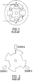
- Fig. 1 shows a schematic diagram of a typical 3-phase SR machine, which has six stator poles and four rotor poles.
- the radially opposed poles carrying windings A and A' (phase A) have opposite magnetic polarisation determined by the arrangement of the windings.
- Phases B and C are formed similarly.
- the timing of the switching of the currents in the windings is controlled according to the relative angular positions of the stator and rotor poles.
- This relative position may be detected by a rotor position transducer (RPT) consisting of a rotating member and stationary sensors which supply signals to the control electronics.
- RPT rotor position transducer
- Fig. 2 illustrates a typical system consisting of a rotating slotted disc and three optical sensors which are switched by the rotation of the disc.
- the RPT typically consists of a vane on the rotor which interrupts one or more slotted optical switches each comprising a light emitting diode (LED) and a phototransistor. Typically, it is necessary to supply the LED with current of the order of 10-20mA in order for the slotted switch to operate.
- LED light emitting diode
- FIG. 3 shows part of a typical converter circuit for a switched reluctance machine.
- the rectifier bridge 8 supplies the dc link 6 from a single phase alternating current supply 4.
- a dc link capacitor 5 acts to smooth the voltage of the dc link.
- FIG. 3 One known arrangement for supplying current to the LED is also-shown in Fig. 3.
- the arrangement shown is of the "resistive dropper" type commonly used in drives which are designed for cost-sensitive applications such as washing machines, vacuum cleaners, dishwashers etc.
- a slotted optical switch is shown generally at 10 and includes an LED 12 and a cooperating phototransistor 14.
- the phototransistor 14 outputs a signal along lines 16 to a control system of any suitable known type to control the switching of the currents in the windings according to the RPT signal.
- the LED 12 supply current is provided by a resistor, or plurality of resistors 18, connected in series to the DC bus.
- the other circuit may comprise an element, or all, of a position sensor for sensing the position of the moving part relative to the stator part.
- a dedicated independent supply is not required for the position sensor.
- Voltage maintaining means for example a capacitor or a capacitor and a resistor in series, may be provided in parallel with the voltage setting means.
- the voltage setting means may comprise a zener diode. The zener diode, when conducting, provides a constant reference voltage for the position sensor. When the zener diode is off, the capacitor substantially maintains the constant voltage until the zener diode conducts again.
- the electric machine may comprise a multi-phase electric machine having respective current energisable means associated with each phase, wherein the current drivable component of the position sensor is provided in a common current path with each current energisable means.
- the position sensor is energised by successive phases, allowing use of a capacitor of reduced value.
- the method may comprise switching the current energisable means to a free-wheeling state and switching a portion of the free-wheeling current to the current drivable means.
- a portion of the stored energy in the energisable means - for example a motor winding - is used.
- the method steps may be carried out during an initial start-up phase of the machine.
- the present invention solves the problems associated with the prior art arrangements by using a proportion of the stored energy in the motor winding that would either circulate in the free wheel loop or return to the DC bus during the energy return phase of operation of an SR machine to power the LED.
- Fig. 4 shows a conventional "two switch per phase” power converter circuit for one phase winding 20 of a switched reluctance motor.
- the circuit comprises the phase winding 20 in series with a "top” switch 28 and a “bottom” switch 24 connected across the dc link.
- a current measurement resistor 30 may be included, typically adjacent to the OV rail, to provide a low-cost method for measuring current.
- Diodes 22 and 26 are connected between the ends of the phase winding and the opposite rail of the DC link. When both switches 28 and 24 are closed, voltage is applied to the phase winding. Flux, which is the time integral of the applied voltage, begins to increase in the magnetic circuit associated with the phase winding, and current is drawn from the supply to support this flux.
- Switches 24,28 can, for example, be power transistors, such as bipolar transistors, insulated gate field effect transistors, power metal oxide silicon field effect transistors etc., controlled by any one of a large number of known methods.
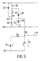
- Fig. 5 shows a power converter circuit according to the invention in which components additional to Fig. 4 have been incorporated to provide a power supply for the LED 12.
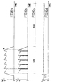
- a typical winding current profile obtainable using the circuit of Fig. 4 for the phase winding 20 is shown.
- the winding 20 is energised rapidly to the value, for example, of 4A by closing both switches 24 and 28 to establish a direct current path through the winding 20 from the positive voltage line to the zero volt line.
- the current, i w rises rapidly to the 4A value.
- the chopping operation comprises repeatedly opening and closing one or other of the switches 24,28 - for example switch 28.
- the circuit allows a proportion of the energy in the winding 20 to power the LED 12 during energy return of free-wheeling portions of the cycle.
- similar reference numerals have been used as in Fig. 4.
- the circuit includes various additional components as described in more detail below connected between the second diode 26 and the zero volt line.
- the additional components include a zener diode 40 (in this example, rated at 5V) connected between the second diode 26 and the zero volt supply line. Also connected between the second diode 26 and the zero volt supply line, in parallel with the zener diode 40, is a series combination of a resistor R1 (in this example 10 ohms) and a capacitor C. The LED 12 and a resistor R2 (in this example 220 ohms) in series therewith are also connected between resistor R1 and the zero volt supply line in parallel with the capacitor C. The value of the capacitor C in this example is 1000 ⁇ F.
- diode 26 prevents current from flowing through the LED and associated components.
- switch 28 When switch 28 is opened, the current flows in the free-wheeling state through resistor 30 and diode 26.
- the zener diode 40 is reverse biased and thus holds the voltage at a point between the zener diode 40 and the second diode 26 at the constant value, in the present example 5V.
- Capacitor C is thus charged to that value through resistor R1 and current simultaneously runs through LED 12 via resistors R1 and R2 such that the LED 12 operates at the desired current level.
- switch 28 When switch 28 is closed once again the current through the zener diode and diode 26 drops to zero.
- the capacitor C acts as a hold-up capacitor which partially discharges across the LED and maintains the LED current.
- the zener diode current drops to zero when the switch 28 is closed once again and the winding current rises, and the pattern repeats at the next chopping step.
- both switches 24,28 are opened, at point M, and the current through the winding 20 begins to decay rapidly through diodes 22 and 26 and the zener diode.
- the on-off period of the winding current pulse is shown in the example of Fig. 6C as being on for 4ms and off for 8ms so that the zener diode 40 conducts for almost 1 / 3 of the time.
- the corresponding LED supply voltage, V c is shown in Fig. 6d.
- the LED supply voltage is maintained substantially at the maximum value of 5V whilst the winding is energised, the hold-up capacitor C maintaining the LED supply voltage when the zener diode current drops to zero briefly during chopping.
- the LED supply voltage decays only slowly because of the capacitor C.
- the supply voltage drops by approximately 0.2V before the winding is energised again. It will be seen, therefore, that once the motor is in operation, the LED supply voltage is maintained at substantially 5V.
- resistor R1 in Figure 5 the main function of resistor R1 in Figure 5 is to limit the initial surge of current into the capacitor. If the capacitor is of sufficient rating, then R1 may be omitted. However it will generally be found that the incorporation of R1 is cost-effective in that it allows a significant reduction in the cost of the capacitor.
- the motor can now operate conventionally, the current to the LED 12 being maintained by periodically topping up the reservoir capacitor each time the winding is being de-energised as discussed above.
- the system can also be used to provide a negative supply voltage (as a result of the bias of the zener diode) for any circuit that may require it,for example,analogue comparators.
- the connection 44 in Figure 5 shows where such other circuits could be connected.
- the winding current profile shown in Fig. 6a is typical, for example, of a washing machine drive operating at medium speed, e.g., in wash mode.
- Figs. 7a to 7c show operation at high speed, in which the zener diode 40 conducts for approximately 33% of the time.
- the zener diode current, i z shown in Fig. 7b remains at zero. In this mode no chopping takes place and switches 24,28 are simply opened again once the desired rotor position is reached and the winding current decays to zero once more.
- the winding is energised for approximately 0.2ms and the current decays to zero once more in an equal period of 0.2ms.
- the winding current remains at zero for a further 0.2ms before the winding 20 is re-energised.
- the zener diode current switches on after 0.2ms and decays with the winding current back down to zero after a further 0.2ms.
- the zener diode voltage is maintained at a constant 5V while current flows in the zener diode.
- the LED supply voltage (V c ) is maintained at 5V whilst current flows through the zener diode 40 and decays slowly when the zener diode current is zero because of the capacitor C until current flows once again through the zener diode 40.
- the voltage decays by approximately 8mV whilst the zener diode current is zero, remaining therefore at a sufficient level to maintain suitable current flow through the LED 12.
- a 3-phase motor is shown including windings 20a, 20b and 20c.
- each winding 20a,b,c is also associated with a respective zener diode 40a,b,c and resistor R1a,b,c.
- Each of the phases is connected via R1 to a common LED 12, resistor R2 and parallel capacitor C such that the current in each winding 20a,b,c is used in turn to power the LED 12.
- the capacitor C need only be of a high enough value to maintain the LED at a suitable voltage during chopping in each phase and need not sustain a suitable voltage for the time during which a given phase is off.
- this system is achieved at the expense of additional components such as the zener diodes 40b,c and the resistors R1b,c.
- Further diodes 50a,b,c are connected between each resistor R1a,b,c and the resistor R2 and capacitor C to prevent current flow between windings 20a,b,c.
- zener diode 40 and capacitor C arrangement discussed above could be replaced by any appropriate circuitry.
- the particular effect of the zener diode 40 is that it maintains constant the voltage across the LED 12 and resistors R1 and R2, allowing controllable constant current flow through the LED.
- the particular effect of the capacitor C is that of holding the voltage substantially constant at these times where the zener diode 40 is off.
- the present invention is applicable to inverted machines in which the stator is in the centre of the machine and the rotor is arranged to rotate around the outside of the stator.
- the invention is applicable to linear machines as well as rotary ones.
- the term rotor is often used in relation to linear machines to describe the moving member.
- the term rotor used herein is intended to embrace such moving members of linear machines.
Landscapes
- Engineering & Computer Science (AREA)
- Power Engineering (AREA)
- Physics & Mathematics (AREA)
- General Physics & Mathematics (AREA)
- Control Of Electric Motors In General (AREA)
- Brushless Motors (AREA)
- Connection Of Motors, Electrical Generators, Mechanical Devices, And The Like (AREA)
Claims (11)
- Elektrische Maschine, mit einem Statorteil und einem bewegten Teil, durch Strom erregbare Mittel (20), welche an dem einen oder dem anderen Teil vorgesehen sind, wobei die Mittel erregbar sind, um den bewegten Teil relativ zum Statorteil anzutreiben, einen ersten Kreis, der die durch Strom erregbaren Mittel und Spannungseinstellmittel (40) enthält, welche in einem gemeinsamen Strompfad mit den durch Strom erregbaren Mitteln angeordnet sind, wobei beim Betrieb der elektrischen Maschine Strom in dem ersten Kreis fließt, dadurch gekennzeichnet, daß die elektrische Maschine des weiteren einen anderen Kreis enthält, welcher durch den ersten Kreis mit einer im wesentlichen konstanten Spannung (Vz) gespeist wird, die in diesem durch die Spannungseinstellmittel herbeigeführt wird.
- Elektrische Maschine nach Anspruch 1, wobei der andere Kreis alle oder ein Element (12) eines Positionssensors (10) zum Erfassen der Position des bewegten Teils relativ zum Statorteil enthält.
- Elektrische Maschine nach Anspruch 1, wobei Spannungserhaltungsmittel (C) parallel zu den Spannungseinstellmitteln vorgesehen sind.
- Elektrische Maschine nach Anspruch 1, 2 oder 3, wobei die Spannungseinstellmittel eine Zener-Diode (40) enthalten.
- Elektrische Maschine nach Anspruch 3, wobei die Spannungserhaltungsmittel einen Kondensator (C) oder einen in Serie geschalteten Kondensator und Widerstand (R1) enthalten.
- Elektrische Maschine nach einem der vorangehenden Ansprüche, umfassend eine mehrphasige elektrische Maschine, welche entsprechende durch Strom erregbare Mittel (20a;b;c) aufweist, die der jeweiligen Phase zugeordnet sind, wobei die Spannungseinstellmittel (40a;b;c) in einem gemeinsamen Strompfad mit jedem durch Strom erregbaren Mittel vorgesehen sind.
- Elektrische Maschine nach einem der Ansprüche 1 bis 6, die einen Zwei-Schalter-pro-Phase-Schaltkreis aufweist, welcher zu einer Freilaufschleife konfiguriert werden kann, die die durch Strom erregbaren Mittel und die Spannungseinstellmittel enthält.
- Verfahren zum Liefern von Strom an einen anderen Kreis in einer elektrischen Maschine, wobei die elektrische Maschine einen Statorteil und einen beweglichen Teil und durch Strom erregbare Mittel (20) aufweist, welche an dem einen Teil öder dem anderen Teil vorgesehen sind, wobei die Mittel erregbar sind, um den beweglichen Teil relativ zum Statorteil anzutreiben, wobei die durch Strom erregbaren Mittel Teil eines ersten Kreises sind, gemeinsam mit den Spannungseinstellmitteln (40), die in einem gemeinsamen Strompfad damit angeordnet sind, wobei während des Betriebs der elektrischen Maschine Strom in dem ersten Kreis fließt, wobei das Verfahren gekennzeichnet ist durch:das Speisen des anderen Kreises durch den ersten Kreis mit einer im wesentlichen konstanten Spannung (Vz), welche durch die Spannungseinstellmittel in diesem herbeigeführt wird.
- Verfahren nach Anspruch 8, wobei der andere Kreis alle oder ein Element (12) eines Positionssensors (10) zum Erfassen der Position des beweglichen Teils relativ zum Statorteil enthält.
- Verfahren nach Anspruch 8 oder 9, weiters umfassend das Schalten der durch Strom erregbaren Mittel in einen Freilaufzustand und Ableiten des Stroms von dem Freilaufstrom für den anderen Kreis.
- Verfahren nach einem der Ansprüche 8 bis 10, wobei der Strom während einer anfänglichen Hochfahrphase der Maschine abgeleitet wird.
Applications Claiming Priority (2)
| Application Number | Priority Date | Filing Date | Title |
|---|---|---|---|
| GBGB9623865.4A GB9623865D0 (en) | 1996-11-15 | 1996-11-15 | An electric machine |
| GB9623865 | 1996-11-15 |
Publications (3)
| Publication Number | Publication Date |
|---|---|
| EP0843405A2 EP0843405A2 (de) | 1998-05-20 |
| EP0843405A3 EP0843405A3 (de) | 1999-04-28 |
| EP0843405B1 true EP0843405B1 (de) | 2002-05-29 |
Family
ID=10803052
Family Applications (1)
| Application Number | Title | Priority Date | Filing Date |
|---|---|---|---|
| EP97308814A Expired - Lifetime EP0843405B1 (de) | 1996-11-15 | 1997-11-03 | Elektrische Maschine |
Country Status (6)
| Country | Link |
|---|---|
| US (1) | US5894211A (de) |
| EP (1) | EP0843405B1 (de) |
| CN (1) | CN1069793C (de) |
| DE (1) | DE69712854T2 (de) |
| GB (1) | GB9623865D0 (de) |
| TW (1) | TW347607B (de) |
Cited By (1)
| Publication number | Priority date | Publication date | Assignee | Title |
|---|---|---|---|---|
| US7201244B2 (en) | 2003-10-03 | 2007-04-10 | Letourneau, Inc. | Vehicle for materials handling and other industrial uses |
Families Citing this family (8)
| Publication number | Priority date | Publication date | Assignee | Title |
|---|---|---|---|---|
| GB0113776D0 (en) * | 2001-06-06 | 2001-07-25 | Switched Reluctance Drives Ltd | Excitation of switched reluctance motors |
| JP4150623B2 (ja) * | 2003-04-04 | 2008-09-17 | 株式会社デンソー | 回転体制御装置 |
| GB0310491D0 (en) * | 2003-05-07 | 2003-06-11 | Switched Reluctance Drives Ltd | Excitation of switched reluctance motors |
| US7633259B2 (en) * | 2006-07-31 | 2009-12-15 | General Electric Company | Method and apparatus for operating electrical machines |
| GB2503670B (en) | 2012-07-03 | 2014-12-10 | Dyson Technology Ltd | Method of preheating a brushless motor |
| GB2503671B (en) * | 2012-07-03 | 2014-12-17 | Dyson Technology Ltd | Control of a brushless motor |
| EP2712075B1 (de) * | 2012-09-20 | 2018-03-07 | Perkins Engines Company Limited | Verfahren zur Steuerung einer geschalteten Reluktanzmaschine |
| RU181759U1 (ru) * | 2017-09-26 | 2018-07-26 | Общество с ограниченной ответственностью "ПромЭлКом" | Индукторный привод вспомогательных машин тягового подвижного состава |
Family Cites Families (13)
| Publication number | Priority date | Publication date | Assignee | Title |
|---|---|---|---|---|
| US4500824A (en) * | 1984-05-21 | 1985-02-19 | General Electric Company | Method of commutation and converter circuit for switched reluctance motors |
| US5075610A (en) * | 1991-03-28 | 1991-12-24 | Honeywell Inc. | Switched reluctance motor control circuit with energy recovery capability |
| GB9120404D0 (en) * | 1991-09-25 | 1991-11-06 | Switched Reluctance Drives Ltd | Control of switched reluctance machines |
| US5252907A (en) * | 1992-04-20 | 1993-10-12 | Honeywell, Inc. | Circuit arrangement for mitigating power switch capacitance |
| US5287372A (en) * | 1992-04-24 | 1994-02-15 | Hughes Aircraft Company | Quasi-resonant diode drive current source |
| US5280421A (en) * | 1992-06-17 | 1994-01-18 | General Electric Company | Current regulator for a four-legged three-phase inverter |
| US5424624A (en) * | 1993-02-08 | 1995-06-13 | Dana Corporation | Driver circuit for electric actuator |
| US5381081A (en) * | 1993-05-27 | 1995-01-10 | General Electric Company | Switched reluctance generator for generating AC power |
| GB9311694D0 (en) * | 1993-06-07 | 1993-07-21 | Switched Reluctance Drives Ltd | Electric machine rotor prosition encoder |
| US5489831A (en) * | 1993-09-16 | 1996-02-06 | Honeywell Inc. | Pulse width modulating motor controller |
| US5433283A (en) * | 1993-10-27 | 1995-07-18 | Sgs-Thomson Microelectronics, Inc. | Apparatus for controlling a throttle plate of a carburetor of an internal combustion engine in response to loss of traction by a driving wheel, or other similar condition |
| GB9414005D0 (en) * | 1994-07-12 | 1994-08-31 | Switched Reluctance Drives Ltd | Switched electric machine controller |
| US5742146A (en) * | 1996-12-03 | 1998-04-21 | Magnetek, Inc. | Drive circuit for a switched reluctance motor with improved energy recovery using a common dump capacitor and recovering phase circuit |
-
1996
- 1996-11-15 GB GBGB9623865.4A patent/GB9623865D0/en active Pending
-
1997
- 1997-11-03 EP EP97308814A patent/EP0843405B1/de not_active Expired - Lifetime
- 1997-11-03 DE DE69712854T patent/DE69712854T2/de not_active Expired - Fee Related
- 1997-11-13 TW TW086116892A patent/TW347607B/zh active
- 1997-11-14 CN CN97122673A patent/CN1069793C/zh not_active Expired - Fee Related
- 1997-11-14 US US08/970,516 patent/US5894211A/en not_active Expired - Lifetime
Cited By (2)
| Publication number | Priority date | Publication date | Assignee | Title |
|---|---|---|---|---|
| US7201244B2 (en) | 2003-10-03 | 2007-04-10 | Letourneau, Inc. | Vehicle for materials handling and other industrial uses |
| US7318580B2 (en) | 2003-10-03 | 2008-01-15 | Letourneau Technologies, Inc. | Vehicle for materials handling and other industrial uses |
Also Published As
| Publication number | Publication date |
|---|---|
| DE69712854T2 (de) | 2002-11-14 |
| GB9623865D0 (en) | 1997-01-08 |
| US5894211A (en) | 1999-04-13 |
| DE69712854D1 (de) | 2002-07-04 |
| CN1069793C (zh) | 2001-08-15 |
| EP0843405A3 (de) | 1999-04-28 |
| CN1182971A (zh) | 1998-05-27 |
| TW347607B (en) | 1998-12-11 |
| EP0843405A2 (de) | 1998-05-20 |
Similar Documents
| Publication | Publication Date | Title |
|---|---|---|
| AU719478B2 (en) | Brushless DC motor control | |
| US6014003A (en) | Method and apparatus for controlling a switched reluctance machine | |
| EP0851570B1 (de) | Vorrichtung zur Steuerung eines Synchronomotors mit einem Dauermagnetläufer | |
| EP1208643B1 (de) | Ansteuerung einer elektrischen reluktanzmaschine | |
| US4961038A (en) | Torque estimator for switched reluctance machines | |
| EP1471629B1 (de) | Bestimmung der Rotorlage in einem Reluktanzmotor | |
| US5491398A (en) | Repulsion motor | |
| KR100400516B1 (ko) | 스위치 릴럭턴스 기계용 콘트롤러 | |
| US3969658A (en) | Motor and control system having cyclic reversal and unidirectional capabilities | |
| WO2009023190A1 (en) | Single switch controlled switched reluctance machine | |
| EP1530283B1 (de) | Betreiben einer elektrischen Maschine | |
| EP0843405B1 (de) | Elektrische Maschine | |
| US6049187A (en) | Speed control for brushless repulsion motor | |
| US20020190684A1 (en) | Control strategy for switched reluctance drive systems | |
| CA2232888C (en) | Simplified control for running a switched reluctance motor | |
| US5793169A (en) | Method and apparatus for controlling static electronic components for phase switching in a three-phase brushless electric motor | |
| JPS644439B2 (de) | ||
| EP0387358B1 (de) | Gleichstrommotor | |
| WO2005062457A1 (en) | Three-wire reversing system | |
| WO1995022195A1 (en) | Brushless d.c. motor | |
| JPS6220788B2 (de) | ||
| HK1024112B (en) | Brushless dc motor control | |
| KR20000005399A (ko) | 스위치식 자기 저항 기계를 제어하기 위한 증진된 방법 및 장치 | |
| JPH07118942B2 (ja) | ブラシレスモ−タのコイル焼損防止装置 | |
| JPS61295894A (ja) | 無整流子電動機の駆動装置 |
Legal Events
| Date | Code | Title | Description |
|---|---|---|---|
| PUAI | Public reference made under article 153(3) epc to a published international application that has entered the european phase |
Free format text: ORIGINAL CODE: 0009012 |
|
| AK | Designated contracting states |
Kind code of ref document: A2 Designated state(s): DE FR GB IT |
|
| PUAL | Search report despatched |
Free format text: ORIGINAL CODE: 0009013 |
|
| AK | Designated contracting states |
Kind code of ref document: A3 Designated state(s): AT BE CH DE DK ES FI FR GB GR IE IT LI LU MC NL PT SE |
|
| 17P | Request for examination filed |
Effective date: 19990906 |
|
| AKX | Designation fees paid |
Free format text: AT BE CH DE LI |
|
| RBV | Designated contracting states (corrected) |
Designated state(s): DE FR GB IT |
|
| 17Q | First examination report despatched |
Effective date: 20000711 |
|
| GRAG | Despatch of communication of intention to grant |
Free format text: ORIGINAL CODE: EPIDOS AGRA |
|
| GRAG | Despatch of communication of intention to grant |
Free format text: ORIGINAL CODE: EPIDOS AGRA |
|
| GRAH | Despatch of communication of intention to grant a patent |
Free format text: ORIGINAL CODE: EPIDOS IGRA |
|
| GRAG | Despatch of communication of intention to grant |
Free format text: ORIGINAL CODE: EPIDOS AGRA |
|
| GRAH | Despatch of communication of intention to grant a patent |
Free format text: ORIGINAL CODE: EPIDOS IGRA |
|
| GRAA | (expected) grant |
Free format text: ORIGINAL CODE: 0009210 |
|
| AK | Designated contracting states |
Kind code of ref document: B1 Designated state(s): DE FR GB IT |
|
| REG | Reference to a national code |
Ref country code: GB Ref legal event code: FG4D |
|
| REF | Corresponds to: |
Ref document number: 69712854 Country of ref document: DE Date of ref document: 20020704 |
|
| ET | Fr: translation filed | ||
| PLBE | No opposition filed within time limit |
Free format text: ORIGINAL CODE: 0009261 |
|
| STAA | Information on the status of an ep patent application or granted ep patent |
Free format text: STATUS: NO OPPOSITION FILED WITHIN TIME LIMIT |
|
| 26N | No opposition filed |
Effective date: 20030303 |
|
| PGFP | Annual fee paid to national office [announced via postgrant information from national office to epo] |
Ref country code: DE Payment date: 20061026 Year of fee payment: 10 |
|
| PGFP | Annual fee paid to national office [announced via postgrant information from national office to epo] |
Ref country code: FR Payment date: 20061108 Year of fee payment: 10 |
|
| PGFP | Annual fee paid to national office [announced via postgrant information from national office to epo] |
Ref country code: IT Payment date: 20061130 Year of fee payment: 10 |
|
| PG25 | Lapsed in a contracting state [announced via postgrant information from national office to epo] |
Ref country code: DE Free format text: LAPSE BECAUSE OF NON-PAYMENT OF DUE FEES Effective date: 20080603 |
|
| REG | Reference to a national code |
Ref country code: FR Ref legal event code: ST Effective date: 20080930 |
|
| PG25 | Lapsed in a contracting state [announced via postgrant information from national office to epo] |
Ref country code: FR Free format text: LAPSE BECAUSE OF NON-PAYMENT OF DUE FEES Effective date: 20071130 |
|
| PG25 | Lapsed in a contracting state [announced via postgrant information from national office to epo] |
Ref country code: IT Free format text: LAPSE BECAUSE OF NON-PAYMENT OF DUE FEES Effective date: 20071103 |
|
| PGFP | Annual fee paid to national office [announced via postgrant information from national office to epo] |
Ref country code: GB Payment date: 20151103 Year of fee payment: 19 |
|
| GBPC | Gb: european patent ceased through non-payment of renewal fee |
Effective date: 20161103 |
|
| PG25 | Lapsed in a contracting state [announced via postgrant information from national office to epo] |
Ref country code: GB Free format text: LAPSE BECAUSE OF NON-PAYMENT OF DUE FEES Effective date: 20161103 |