EP0843502A1 - Circuit de détection et prévention d'effet Larsen et un système de haut-parleur utilisant celui-ci - Google Patents
Circuit de détection et prévention d'effet Larsen et un système de haut-parleur utilisant celui-ci Download PDFInfo
- Publication number
- EP0843502A1 EP0843502A1 EP97119800A EP97119800A EP0843502A1 EP 0843502 A1 EP0843502 A1 EP 0843502A1 EP 97119800 A EP97119800 A EP 97119800A EP 97119800 A EP97119800 A EP 97119800A EP 0843502 A1 EP0843502 A1 EP 0843502A1
- Authority
- EP
- European Patent Office
- Prior art keywords
- howling
- section
- frequency band
- identifying
- prevention circuit
- Prior art date
- Legal status (The legal status is an assumption and is not a legal conclusion. Google has not performed a legal analysis and makes no representation as to the accuracy of the status listed.)
- Granted
Links
Images


Classifications
-
- H—ELECTRICITY
- H04—ELECTRIC COMMUNICATION TECHNIQUE
- H04R—LOUDSPEAKERS, MICROPHONES, GRAMOPHONE PICK-UPS OR LIKE ACOUSTIC ELECTROMECHANICAL TRANSDUCERS; ELECTRIC HEARING AIDS; PUBLIC ADDRESS SYSTEMS
- H04R3/00—Circuits for transducers
- H04R3/02—Circuits for transducers for preventing acoustic reaction, i.e. acoustic oscillatory feedback
Definitions
- This invention relates to a howling detection and prevention circuit and a loudspeaker system employing this circuit.
- a loud sound produced by the loudspeker is sometimes accompanied by howling.
- a user manipulates a volume control while confirming presence or absence of howling to set the entire gain of radiation of acoustic power to a level at which howling is not produced or sets the entire gain after decreasing the gain of a particular frequency region by using a graphic equalizer or a notch filter. Adjustment of the gain is made relying upon the user's hearing.
- the user usually hurries to the loudspeaker system and stops howling by lowering the volume level. In such a case, it takes time before howling stops and the user cannot avoid unpleasantness caused by howling during this time.
- an object of the invention to provide a howling detection and prevention circuit capable of automatically detecting and preventing howling and a loudspeaker system employing the same circuit.
- a howling detection and prevention circuit which receives an output of a microphone as its input signal and detects howling therein comprising a computing section which divides frequency of the input signal into a plurality of frequency bands on the basis of a predetermined sampling period and computes power of each of the frequency bands, an identifying section which sequentially shifts the frequency band and identifies whether howling exists or not in accordance with a predetermined condition by employing value of the computed power of each frequency band, and a gain adjusting section which, when howling has been detected as a result of the identifying, adjusts gain of the frequency band in which the howling has been detected to prevent the howling.
- an input signal is
- the condition of howling is searched by sequentially changing the frequency band and, when there is a frequency band which satisfies the howling condition, this band is detected as a howling frequency band and prevention of howling is performed.
- a loudspeaker system and a PA (public address) system using a microphone howling which occurs when sound volume is raised above a certain value can be automatically detected.
- the howling can be prevented by automatically adjusting gain of the frequency band. Accordingly, howling can be automatically prevented without requiring a user's manipulation.
- the howling detection and prevention circuit further comprises an entire gain adjusting section which adjusts entire gain of all of the frequency bands in accordance with the result of the identifying by the identifying section to prevent the howling.
- said computing section computes power of each frequency band by computing moving averages with respect to each of the frequency bands which has been provided by frequency division on the basis of the predetermined sampling period.
- said identifying section identifies presence or absence of howling on the basis difference between an absolute value of a power in the frequency band under identifying and a power of the frequency band in the vicinity thereof.
- a loudspeaker system comprising a microphone, a howling detection and prevention circuit described above which receives a signal from the microphone as its input signal, an amplifying section which amplifies an output signal of the howling detection and prevention circuit, and a loudspeaker which is driven by an output of the amplifying section.
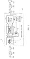
- Fig. 1 shows an embodiment of a howling detection and prevention circuit according to the invention and a loudspeaker system incorporating this circuit.
- a loudspeaker system 100 includes a microphone 101, a microphone amplifier 102 which amplifies an output signal of the microphone 101, an analog-to-digital converter 103 which converts the analog output signal of the microphone amplifier 102 to a digital signal, a howling detection and prevention circuit 1 which receives the digital output of the analog-to-digital converter 103 as an input signal, processes this input signal and supplies the result of processing to a digital-to-analog converter 104, a power amplifier 105 which amplifies the output signal of the digital-to-analog converter 104 in accordance with a gain which has been set at a desired value by an operator, and a loudspeaker 106 which is driven by the output signal of the power amplifier 105.
- the howling detection and prevention circuit 1 includes various circuits such as a microcomputer, a signal processing chip, a memory and a timer. In Fig. 1, the internal structure of the circuit 1 is illustrated by blocks representing respective functions of the circuit 1.
- a digital signal provided from the analog-to-digital converter 103 is applied to a band dividing filter section 11 of the howling detection and prevention circuit 1.
- the band dividing filter section 11 consists of M (an integer including 2 and over) FIR (finite impulse response) bandpass filters or IIR (infinite impulse response) bandpass filters whose center frequencies are sequentially shifted.
- the band dividing filter section 11 divides the input signal from the analog-to-digital converter 103 into signals of M frequency bands and, after imparting a predetermined gain to these signals, supplies these signals as signals F1, F2, Across FM to both an each band power computing section 12 and an adding section 13.
- the each band power computing section 12 computes power values P1, P2, Across PM of the signals F1, F2, .
- the adding section 13 adds the signals F1, F2, Across FM of the M bands together to obtain the signal of the entire bands and supplies the result of the addition to an entire gain control section 15.
- the howling identifying section 14 identifies the state of occurrence of howling on the basis the power values P1, P2, Across PM of the signals in the respective bands and establishes, on the basis of the result of the identifying, a gain of each band which is used in the band dividing filter section 11 and also establishes a gain G for the signal of the entire bands which is used in the entire gain control section 15.
- the entire gain control section 15 multiplies the sum signal of the entire bands with the gain G and supplies the result of the computation to the digital-to-analog converter 104.
- the howling detection and prevention circuit 1 reduces, on the basis of the result of the identifying as to howling, a gain of a band in which howling has occurred or is likely to occur and thereby prevents occurrence of howling. In a case where howling remains unstopped despite the set gain for the band has been reduced, the howling can be stopped by reducing the entire gain G. By this arrangement, howling can be completely prevented even when an excessive gain has been set by the user.
- the circuit block shown in Fig. 2 is a structure for computing a power of one frequency band in the each band power computing section 12 and the each band power computing section 12 has M blocks of the same construction.
- the squarer 121a computes square value X0 2 of the input signal X0 and supplies the result X0 2 to the adder-subtractor 121b and to each input terminal of the N-tap shift memory 122.
- the adder-subtractor 121b adds a computed value P obtained in the preceding sampling period k-1 and the square value X0 2 provided by the squarer 121a together and subtracts from the sum of this addition a value XN 2 (A) of the last stage of the N-tap shift memory 122 before shifting the memory (i.e., the output of the N-th tap) thereby to obtain a new computed value P.
- the N-tap shift memory 122 sequentially shifts stored values of N memories and stores, as a value X1 2 (B), result of computation X0 2 of the squarer 121a in the current sampling period k.
- Fig. 3 is a diagram showing a circuit block in the howling identifying section 14 for identifying whether howling has occurred or not or howling is likely to occur or not.
- the howling identifying section 14 has, in addition to this circuit block, a circuit for selecting an input signal and a circuit for setting gains used in the band dividing filter section 11 and the entire gain control section 15 on the basis of the result of the identifying.
- input signals Pm, Pm-1, Pm+1, Pm-2 and Pm+2 represent five signals consisting of a power signal Pm of a desired band in the power values P1, P2, Across PM of Fig.
- comparison circuits 144, 145, 146, 147 and 148 perform comparison as to whether or not conditions Pm > TL1, Pm - Pm-1 >D1F1, Pm - Pm+1 > D1F1, Pm - Pm-2 > D1F2 and Pm - Pm+2 > D1F2 exist and output a result of comparison "0" (the condition is not satisfied) or "1" (the condition is satisfied).
- TL1, D1F1 and D1F2 are reference values which are used for the comparison and set in conformity with actual conditions of use of the loudspeaker system.
- An AND circuit 149 seeks a logical sum of results of comparison of all comparison circuits 144 to 148 and, when all of the conditions of comparison have been satisfied, outputs a signal "1" which represents the result of identifying that howling has occurred or is likely to occur.
- Fig. 4 is a diagram which schematically shows an example of relation between the comparison reference values TL1, D1F1 and D1F2 and the input signals Pm, Pm-1, Pm-2, Pm+1 and Pm+2.
- the example of Fig. 4 is illustrated on the assumption that the power signal Pm of the center frequency band has satisfied the above condition of identifying and therefore a howling states exists.
- a signal of a frequency band in which howling has occurred or howling is likely to occur has a larger power than signals of frequency bands in the vicinity thereof and this relation is as illustrated in Fig. 4.
- the signal which has satisfied the condition i.e., the power signal Pm of the center frequency band
- the power signal Pm of the center frequency band has a peak with respect to signals of frequency bands in the vicinity thereof or not
- the reference values D1F1 and D1F2 are normally set so that D1F1 becomes larger than D1F2.
- D1F1 and D1F2 are normally set so that D1F1 becomes larger than D1F2.
- This condition can be judged by comparing the power signal Pm with the reference value TL1, i.e., using not only identifying of difference value but also identifying of the absolute value.
- both identifying of the absolute value i.e., as to whether the power signal Pm is larger than the reference value TL1 or not and identifying of the difference value, i.e., as to whether the power signal Pm is larger than the reference values D1F1 and F1F2 or not are made and, when both conditions are satisfied, it is judged that frequency band of the power signal Pm is in a howling state.
- the howling identifying section 14 shifts the center frequency sequentially and performs judgment as to whether there is a frequency band which satisfies the howling condition and determines a band which satisfies the howling condition as the howling frequency band.
- the howling identifying section 14 reduces the value of the gain used in the entire gain control section 15. By this operation, occurrence of howling which cannot be prevented by reducing the gain of the divided frequency band can be completely prevented.
- identifying of howling can be made in real time and gain of each frequency band or entire gain can be adjusted automatically, so that prevention of howling which relied mainly upon the user's operation can be automatically performed.
- the invention relates to a howling detection and prevention circuit which receives an output of a microphone as its input signal and detects howling therein comprising: a computing section; an identifying section; and a gain adjusting section.
Landscapes
- Health & Medical Sciences (AREA)
- General Health & Medical Sciences (AREA)
- Otolaryngology (AREA)
- Physics & Mathematics (AREA)
- Engineering & Computer Science (AREA)
- Acoustics & Sound (AREA)
- Signal Processing (AREA)
- Circuit For Audible Band Transducer (AREA)
- Control Of Amplification And Gain Control (AREA)
- Reverberation, Karaoke And Other Acoustics (AREA)
Applications Claiming Priority (2)
| Application Number | Priority Date | Filing Date | Title |
|---|---|---|---|
| JP302194/96 | 1996-11-13 | ||
| JP30219496A JP3152160B2 (ja) | 1996-11-13 | 1996-11-13 | ハウリング検出防止回路及びそれを用いた拡声装置 |
Publications (2)
| Publication Number | Publication Date |
|---|---|
| EP0843502A1 true EP0843502A1 (fr) | 1998-05-20 |
| EP0843502B1 EP0843502B1 (fr) | 2007-10-10 |
Family
ID=17906077
Family Applications (1)
| Application Number | Title | Priority Date | Filing Date |
|---|---|---|---|
| EP97119800A Expired - Lifetime EP0843502B1 (fr) | 1996-11-13 | 1997-11-12 | Circuit de détection et prévention d'effet Larsen et un système de haut-parleur utilisant celui-ci |
Country Status (4)
| Country | Link |
|---|---|
| US (1) | US6252969B1 (fr) |
| EP (1) | EP0843502B1 (fr) |
| JP (1) | JP3152160B2 (fr) |
| DE (1) | DE69738193T2 (fr) |
Cited By (8)
| Publication number | Priority date | Publication date | Assignee | Title |
|---|---|---|---|---|
| WO2001003466A3 (fr) * | 1999-07-02 | 2001-05-17 | Koninkl Philips Electronics Nv | Systeme de protection de haut-parleur contenant une commande de puissance audio a selection de bande de frequences |
| GB2414370A (en) * | 2004-03-30 | 2005-11-23 | Yamaha Corp | Howling frequency component emphasis |
| WO2006063624A1 (fr) * | 2004-12-16 | 2006-06-22 | Widex A/S | Audiophone avec estimation de gain modele d'effet larsen |
| EP1903833A1 (fr) * | 2006-09-21 | 2008-03-26 | Phonic Ear Incorporated | Suppression de rétroaction dans un système sonore |
| WO2011090386A1 (fr) * | 2010-01-19 | 2011-07-28 | Squarehead Technology As | Annulation de rétroaction qui dépend de l'emplacement |
| WO2018048678A1 (fr) * | 2016-09-08 | 2018-03-15 | Continental Automotive Systems, Inc. | Prévention du sifflement de communication dans un véhicule |
| CN113316074A (zh) * | 2021-05-11 | 2021-08-27 | 紫光展锐(重庆)科技有限公司 | 一种啸叫检测方法、装置及电子设备 |
| WO2025241138A1 (fr) * | 2024-05-23 | 2025-11-27 | Harman International Industries , Incorporated | Procédé et appareil de traitement audio |
Families Citing this family (30)
| Publication number | Priority date | Publication date | Assignee | Title |
|---|---|---|---|---|
| JP3968612B2 (ja) | 1998-01-27 | 2007-08-29 | 三菱電機株式会社 | 全真空断熱箱体及びその全真空断熱箱体を用いた冷蔵庫並びにその全真空断熱箱体の製造方法及び解体方法 |
| US6665411B2 (en) * | 2001-02-21 | 2003-12-16 | Digisonix Llc | DVE system with instability detection |
| AUPR604201A0 (en) * | 2001-06-29 | 2001-07-26 | Hearworks Pty Ltd | Telephony interface apparatus |
| JP4681163B2 (ja) * | 2001-07-16 | 2011-05-11 | パナソニック株式会社 | ハウリング検出抑圧装置、これを備えた音響装置、及び、ハウリング検出抑圧方法 |
| JP2003204596A (ja) * | 2002-01-04 | 2003-07-18 | Matsushita Electric Ind Co Ltd | 拡声放送システムおよび拡声放送装置 |
| JP3973929B2 (ja) * | 2002-03-05 | 2007-09-12 | 松下電器産業株式会社 | ハウリング検出装置 |
| US7590250B2 (en) * | 2002-03-22 | 2009-09-15 | Georgia Tech Research Corporation | Analog audio signal enhancement system using a noise suppression algorithm |
| US8271279B2 (en) * | 2003-02-21 | 2012-09-18 | Qnx Software Systems Limited | Signature noise removal |
| US8326621B2 (en) | 2003-02-21 | 2012-12-04 | Qnx Software Systems Limited | Repetitive transient noise removal |
| US7949522B2 (en) | 2003-02-21 | 2011-05-24 | Qnx Software Systems Co. | System for suppressing rain noise |
| US7885420B2 (en) * | 2003-02-21 | 2011-02-08 | Qnx Software Systems Co. | Wind noise suppression system |
| US7895036B2 (en) * | 2003-02-21 | 2011-02-22 | Qnx Software Systems Co. | System for suppressing wind noise |
| US7725315B2 (en) * | 2003-02-21 | 2010-05-25 | Qnx Software Systems (Wavemakers), Inc. | Minimization of transient noises in a voice signal |
| US8073689B2 (en) * | 2003-02-21 | 2011-12-06 | Qnx Software Systems Co. | Repetitive transient noise removal |
| US7912228B2 (en) * | 2003-07-18 | 2011-03-22 | Volkswagen Ag | Device and method for operating voice-supported systems in motor vehicles |
| JP4767166B2 (ja) | 2004-06-16 | 2011-09-07 | パナソニック株式会社 | ハウリング抑圧装置、プログラム、集積回路、およびハウリング抑圧方法 |
| EP1684543A1 (fr) * | 2005-01-19 | 2006-07-26 | Success Chip Ltd. | Procédé à l'affaiblissement de rétroaction électro-acoustique |
| US20060217066A1 (en) * | 2005-03-25 | 2006-09-28 | Siemens Communications, Inc. | Wireless microphone system |
| WO2006123495A1 (fr) * | 2005-05-18 | 2006-11-23 | Matsushita Electric Industrial Co., Ltd. | Appareil d'elimination de sifflement et appareil acoustique |
| JP4596273B2 (ja) * | 2006-06-09 | 2010-12-08 | ヤマハ株式会社 | ハウリングキャンセラおよびプログラム |
| JP4743018B2 (ja) * | 2006-06-23 | 2011-08-10 | ヤマハ株式会社 | ハウリング除去装置 |
| JP4936128B2 (ja) * | 2007-06-07 | 2012-05-23 | 横河電機株式会社 | 損失補償回路 |
| JP4697267B2 (ja) * | 2008-07-01 | 2011-06-08 | ソニー株式会社 | ハウリング検出装置およびハウリング検出方法 |
| DE102010044917B4 (de) * | 2010-09-09 | 2015-01-08 | Iav Gmbh Ingenieurgesellschaft Auto Und Verkehr | Verfahren zur Vermeidung akustischer Rückkopplungen |
| WO2014094242A1 (fr) | 2012-12-18 | 2014-06-26 | Motorola Solutions, Inc. | Procédé et appareil pour atténuer une rétroaction dans un récepteur radio numérique |
| DK2835985T3 (en) | 2013-08-08 | 2017-08-07 | Oticon As | Hearing aid and feedback reduction method |
| JP7159438B2 (ja) * | 2018-07-18 | 2022-10-24 | グーグル エルエルシー | エコー検出 |
| US11350204B2 (en) * | 2020-08-14 | 2022-05-31 | Bose Corporation | Wearable audio device feedforward instability detection |
| CN113225657B (zh) * | 2021-04-16 | 2022-09-30 | 深圳木芯科技有限公司 | 基于双麦克风架构的多通道啸叫抑制方法 |
| JP7713230B2 (ja) * | 2021-11-19 | 2025-07-25 | initiaTec株式会社 | ハウリング検出方法、ハウリング抑制装置 |
Citations (4)
| Publication number | Priority date | Publication date | Assignee | Title |
|---|---|---|---|---|
| JPS59161995A (ja) * | 1983-03-07 | 1984-09-12 | Matsushita Electric Ind Co Ltd | ハウリング抑圧装置 |
| JPS60126998A (ja) * | 1983-12-13 | 1985-07-06 | Matsushita Electric Ind Co Ltd | ハウリング抑圧装置 |
| JPS60176313A (ja) * | 1984-02-21 | 1985-09-10 | Matsushita Electric Ind Co Ltd | ハウリング抑圧装置 |
| US4783819A (en) * | 1986-02-18 | 1988-11-08 | U.S. Philips Corporation | Automatically controlled amplifier arrangement |
Family Cites Families (2)
| Publication number | Priority date | Publication date | Assignee | Title |
|---|---|---|---|---|
| US5442712A (en) * | 1992-11-25 | 1995-08-15 | Matsushita Electric Industrial Co., Ltd. | Sound amplifying apparatus with automatic howl-suppressing function |
| JP3235925B2 (ja) * | 1993-11-19 | 2001-12-04 | 松下電器産業株式会社 | ハウリング抑制装置 |
-
1996
- 1996-11-13 JP JP30219496A patent/JP3152160B2/ja not_active Expired - Fee Related
-
1997
- 1997-11-12 US US08/968,248 patent/US6252969B1/en not_active Expired - Lifetime
- 1997-11-12 DE DE69738193T patent/DE69738193T2/de not_active Expired - Lifetime
- 1997-11-12 EP EP97119800A patent/EP0843502B1/fr not_active Expired - Lifetime
Patent Citations (4)
| Publication number | Priority date | Publication date | Assignee | Title |
|---|---|---|---|---|
| JPS59161995A (ja) * | 1983-03-07 | 1984-09-12 | Matsushita Electric Ind Co Ltd | ハウリング抑圧装置 |
| JPS60126998A (ja) * | 1983-12-13 | 1985-07-06 | Matsushita Electric Ind Co Ltd | ハウリング抑圧装置 |
| JPS60176313A (ja) * | 1984-02-21 | 1985-09-10 | Matsushita Electric Ind Co Ltd | ハウリング抑圧装置 |
| US4783819A (en) * | 1986-02-18 | 1988-11-08 | U.S. Philips Corporation | Automatically controlled amplifier arrangement |
Non-Patent Citations (4)
| Title |
|---|
| BOUDY J ET AL: "HANDS-FREE RADIOTELEPHONES FOR CAR APPLICATIONS", PROCEEDINGS OF THE NORDIC SEMINAR ON DIGITAL MOBILE RADIO COMMUNICATIONS, HELSINKI, DEC. 1 - 3, 1992, no. SEMINAR 5, 1 December 1992 (1992-12-01), TELECOM FINLAND, pages 247 - 253, XP000458658 * |
| PATENT ABSTRACTS OF JAPAN vol. 009, no. 015 (E - 291) 22 January 1985 (1985-01-22) * |
| PATENT ABSTRACTS OF JAPAN vol. 009, no. 284 (E - 357) 12 November 1985 (1985-11-12) * |
| PATENT ABSTRACTS OF JAPAN vol. 010, no. 016 (E - 375) 22 January 1986 (1986-01-22) * |
Cited By (14)
| Publication number | Priority date | Publication date | Assignee | Title |
|---|---|---|---|---|
| KR100886575B1 (ko) * | 1999-07-02 | 2009-03-05 | 코닌클리케 필립스 일렉트로닉스 엔.브이. | 주파수 대역 선택적 오디오 전력 제어부를 갖는 확성기 보호 시스템 |
| WO2001003466A3 (fr) * | 1999-07-02 | 2001-05-17 | Koninkl Philips Electronics Nv | Systeme de protection de haut-parleur contenant une commande de puissance audio a selection de bande de frequences |
| GB2414370A (en) * | 2004-03-30 | 2005-11-23 | Yamaha Corp | Howling frequency component emphasis |
| GB2414370B (en) * | 2004-03-30 | 2006-06-14 | Yamaha Corp | Howling frequency component emphasis method and apparatus |
| US7574005B2 (en) | 2004-03-30 | 2009-08-11 | Yamaha Corporation | Howling frequency component emphasis method and apparatus |
| WO2006063624A1 (fr) * | 2004-12-16 | 2006-06-22 | Widex A/S | Audiophone avec estimation de gain modele d'effet larsen |
| US8019104B2 (en) | 2004-12-16 | 2011-09-13 | Widex A/S | Hearing aid with feedback model gain estimation |
| EP1903833A1 (fr) * | 2006-09-21 | 2008-03-26 | Phonic Ear Incorporated | Suppression de rétroaction dans un système sonore |
| WO2011090386A1 (fr) * | 2010-01-19 | 2011-07-28 | Squarehead Technology As | Annulation de rétroaction qui dépend de l'emplacement |
| WO2018048678A1 (fr) * | 2016-09-08 | 2018-03-15 | Continental Automotive Systems, Inc. | Prévention du sifflement de communication dans un véhicule |
| US9959882B2 (en) | 2016-09-08 | 2018-05-01 | Continental Automotive Systems, Inc. | In-car communication howling prevention |
| CN113316074A (zh) * | 2021-05-11 | 2021-08-27 | 紫光展锐(重庆)科技有限公司 | 一种啸叫检测方法、装置及电子设备 |
| CN113316074B (zh) * | 2021-05-11 | 2022-07-05 | 紫光展锐(重庆)科技有限公司 | 一种啸叫检测方法、装置及电子设备 |
| WO2025241138A1 (fr) * | 2024-05-23 | 2025-11-27 | Harman International Industries , Incorporated | Procédé et appareil de traitement audio |
Also Published As
| Publication number | Publication date |
|---|---|
| EP0843502B1 (fr) | 2007-10-10 |
| DE69738193D1 (de) | 2007-11-22 |
| JPH10145888A (ja) | 1998-05-29 |
| US6252969B1 (en) | 2001-06-26 |
| DE69738193T2 (de) | 2008-07-10 |
| JP3152160B2 (ja) | 2001-04-03 |
Similar Documents
| Publication | Publication Date | Title |
|---|---|---|
| EP0843502A1 (fr) | Circuit de détection et prévention d'effet Larsen et un système de haut-parleur utilisant celui-ci | |
| JP4402977B2 (ja) | 補聴器における動的圧縮 | |
| US7133529B2 (en) | Howling detecting and suppressing apparatus, method and computer program product | |
| JP3235925B2 (ja) | ハウリング抑制装置 | |
| EP1121834B1 (fr) | Protheses auditives fonctionnant d'apres des modeles de compression cochleaire | |
| JP2773656B2 (ja) | ハウリング防止装置 | |
| US7110557B2 (en) | Level adjustment circuit | |
| EP2209326A1 (fr) | Appareil de correction de sensibilité auditive | |
| US8583717B2 (en) | Signal processing circuit | |
| JP2992294B2 (ja) | ノイズ除去方法 | |
| US6362764B1 (en) | Digital to analog conversion apparatus and method with cross-fading between new and old data | |
| EP1343352B1 (fr) | Appareil de microphone/haut-parleur | |
| JP2003501914A (ja) | 補聴器用デジタル・フィルタ | |
| NL1015993C2 (nl) | Werkwijze en inrichting voor het omzetten van een analoog ingangssignaal in een digitaal uitgangssignaal. | |
| JP3109389B2 (ja) | 適応フィルタシステム | |
| JP3683978B2 (ja) | 飽和信号処理装置 | |
| JP3067409B2 (ja) | ハウリング防止プロセッサ | |
| JPH0819088A (ja) | 音響処理方法 | |
| JP3681559B2 (ja) | コンプレッション処理方法および装置 | |
| JP2009200761A (ja) | Agc装置 | |
| JPH0611631Y2 (ja) | ディジタルイコライザ | |
| JP3055559B2 (ja) | デジタルフィルタのフィルタ係数変更方法 | |
| KR100466484B1 (ko) | 신호 처리 장치 | |
| DE202011107988U1 (de) | Automatische Verstärkungsregelung | |
| JP2006203459A (ja) | ハウリング除去装置 |
Legal Events
| Date | Code | Title | Description |
|---|---|---|---|
| PUAI | Public reference made under article 153(3) epc to a published international application that has entered the european phase |
Free format text: ORIGINAL CODE: 0009012 |
|
| AK | Designated contracting states |
Kind code of ref document: A1 Designated state(s): DE FR GB |
|
| AX | Request for extension of the european patent |
Free format text: AL;LT;LV;MK;RO;SI |
|
| 17P | Request for examination filed |
Effective date: 19981119 |
|
| 17Q | First examination report despatched |
Effective date: 19981211 |
|
| AKX | Designation fees paid |
Free format text: DE FR GB |
|
| RBV | Designated contracting states (corrected) |
Designated state(s): DE FR GB |
|
| GRAP | Despatch of communication of intention to grant a patent |
Free format text: ORIGINAL CODE: EPIDOSNIGR1 |
|
| RAP1 | Party data changed (applicant data changed or rights of an application transferred) |
Owner name: YAMAHA CORPORATION |
|
| GRAS | Grant fee paid |
Free format text: ORIGINAL CODE: EPIDOSNIGR3 |
|
| GRAA | (expected) grant |
Free format text: ORIGINAL CODE: 0009210 |
|
| AK | Designated contracting states |
Kind code of ref document: B1 Designated state(s): DE FR GB |
|
| REG | Reference to a national code |
Ref country code: GB Ref legal event code: FG4D |
|
| REF | Corresponds to: |
Ref document number: 69738193 Country of ref document: DE Date of ref document: 20071122 Kind code of ref document: P |
|
| ET | Fr: translation filed | ||
| PLBE | No opposition filed within time limit |
Free format text: ORIGINAL CODE: 0009261 |
|
| STAA | Information on the status of an ep patent application or granted ep patent |
Free format text: STATUS: NO OPPOSITION FILED WITHIN TIME LIMIT |
|
| 26N | No opposition filed |
Effective date: 20080711 |
|
| PGFP | Annual fee paid to national office [announced via postgrant information from national office to epo] |
Ref country code: GB Payment date: 20141112 Year of fee payment: 18 Ref country code: FR Payment date: 20141110 Year of fee payment: 18 Ref country code: DE Payment date: 20141105 Year of fee payment: 18 |
|
| REG | Reference to a national code |
Ref country code: DE Ref legal event code: R119 Ref document number: 69738193 Country of ref document: DE |
|
| GBPC | Gb: european patent ceased through non-payment of renewal fee |
Effective date: 20151112 |
|
| REG | Reference to a national code |
Ref country code: FR Ref legal event code: ST Effective date: 20160729 |
|
| PG25 | Lapsed in a contracting state [announced via postgrant information from national office to epo] |
Ref country code: GB Free format text: LAPSE BECAUSE OF NON-PAYMENT OF DUE FEES Effective date: 20151112 Ref country code: DE Free format text: LAPSE BECAUSE OF NON-PAYMENT OF DUE FEES Effective date: 20160601 |
|
| PG25 | Lapsed in a contracting state [announced via postgrant information from national office to epo] |
Ref country code: FR Free format text: LAPSE BECAUSE OF NON-PAYMENT OF DUE FEES Effective date: 20151130 |