EP0843908B1 - Überspannungsschutzvorrichtung für fernmeldeleitungen - Google Patents
Überspannungsschutzvorrichtung für fernmeldeleitungen Download PDFInfo
- Publication number
- EP0843908B1 EP0843908B1 EP96928848A EP96928848A EP0843908B1 EP 0843908 B1 EP0843908 B1 EP 0843908B1 EP 96928848 A EP96928848 A EP 96928848A EP 96928848 A EP96928848 A EP 96928848A EP 0843908 B1 EP0843908 B1 EP 0843908B1
- Authority
- EP
- European Patent Office
- Prior art keywords
- assembly
- circuit board
- cable
- chassis
- recited
- Prior art date
- Legal status (The legal status is an assumption and is not a legal conclusion. Google has not performed a legal analysis and makes no representation as to the accuracy of the status listed.)
- Expired - Lifetime
Links
Images

Classifications
-
- H—ELECTRICITY
- H01—ELECTRIC ELEMENTS
- H01R—ELECTRICALLY-CONDUCTIVE CONNECTIONS; STRUCTURAL ASSOCIATIONS OF A PLURALITY OF MUTUALLY-INSULATED ELECTRICAL CONNECTING ELEMENTS; COUPLING DEVICES; CURRENT COLLECTORS
- H01R13/00—Details of coupling devices of the kinds covered by groups H01R12/70 or H01R24/00 - H01R33/00
- H01R13/66—Structural association with built-in electrical component
- H01R13/665—Structural association with built-in electrical component with built-in electronic circuit
- H01R13/6666—Structural association with built-in electrical component with built-in electronic circuit with built-in overvoltage protection
-
- H—ELECTRICITY
- H01—ELECTRIC ELEMENTS
- H01R—ELECTRICALLY-CONDUCTIVE CONNECTIONS; STRUCTURAL ASSOCIATIONS OF A PLURALITY OF MUTUALLY-INSULATED ELECTRICAL CONNECTING ELEMENTS; COUPLING DEVICES; CURRENT COLLECTORS
- H01R31/00—Coupling parts supported only by co-operation with counterpart
- H01R31/06—Intermediate parts for linking two coupling parts, e.g. adapter
Definitions
- This invention relates to the protection of telecommunications lines from transient voltage surges, such as those due to lightning, and, more particularly, to an assembly for providing such protection to a plurality of transmission line-pairs carried by a multi-conductor cable.
- An assembly for protection of transmission lines with the features of the first part of claim 1 is, for instance, known from US-A-4 799 901.
- Telecommunications transmission lines are typically susceptible to lightning strikes when not within a building. Accordingly, primary lightning protection is usually provided where the transmission lines enter a building.
- modern telecommunications equipment such as computer controlled private branch exchanges, are very sensitive to transient surges such as those caused by lightning strikes and the primary lightning protection is often inadequate.
- Telecommunications equipment manufacturers therefore commonly provide secondary surge protection within their equipment.
- Such equipment for example, a computer controlled private branch exchange, may have twenty, fifty or even more, telephone line-pairs connected thereto. Therefore, if the secondary surge protection is incorporated within the equipment, this leads to a number of disadvantages.
- a known overvoltage protection apparatus is disclosed in U.S. Patent No. 5,359,657 to Pelegris. There is disclosed an overvoltage protection apparatus used with a single pair of telephone lines including clamping circuitry for voltage clamping at a predetermined voltage potential. A single apparatus must be used for each pair of telephone lines in a telecommunications system. A telecommunications system typically comprises multiple line pairs, multiple apparatus therefore consume a large amount of space in a telecommunications equipment system. This is in contravention of the desire to miniaturize and increase the density of telecommunications equipment.
- the secondary protection is contained within an adaptor housing connected between two multi-conductor cables with a plurality of the housings stached together.
- the first cable is relatively short and is connected to the primary protection. This short cable can be thick.
- the second cable is connected to the telecommunications equipment and is relatively thin. Since the telecommunications equipment can be located at a substantial distance from the primary protection, a significant cost saving results from being able to utilize a thinner cable.
- an adaptor assembly mounted to a grounded chassis and connected between first and second multi-conductor cables carrying a plurality of transmission line-pairs.
- the cables are terminated respectively by first and second cable connectors.
- the assembly provides transient voltage surge protection to the plurality of line-pairs, wherein the transient voltage surge protection for each of the line-pairs is provided by a three-terminal protective network having its first and second terminals adapted to be coupled to respective wires of each line-pair and its third terminal adapted to be connected to ground.
- the assembly comprises a circuit board having a ground plane and third and fourth cable connectors mounted to the circuit board in spaced relationship, with the third cable connector being matable with the first cable connector and the fourth cable connector being matable with the second cable connector.
- the assembly further comprises means for mounting the protective network to the circuit board, and means for coupling the first and second terminals of the protective network to the third and fourth cable connectors so that when the first cable connector is mated with the third cable connector and the second cable connector is mated with the fourth cable connector, the protective network is coupled to each of the line-pairs.
- the assembly comprises means for connecting the third terminal of the protective network to the circuit board ground plane, and mounting means for connecting the circuit board ground plane to the chassis.
- the assembly further includes a plurality of resettable fuse elements, each of the fuse elements corresponding to a respective conductor of the first cable and a respective conductor of the second cable.
- the assembly also includes means for mounting the fuse elements to the circuit board and means for connecting the fuse elements to the third and fourth cable connectors so that each of the fuse elements is in series between respective conductors of the first and second cables connected to the assembly.
- Figure 1 illustrates protective circuitry mounted to a printed circuit board contained within a housing of an assembly according to the present invention which is adapted to be interposed between cables containing transmission line-pairs and extending between primary lightning protection and telecommunications equipment.
- the circuitry includes a connector 10 matable with a connector terminating a cable coupled to the primary lightning protection and a connector 12 matable with a connector terminating a cable coupled to the telecommunications equipment.
- Respective line-pairs within each of the cables are interconnected by respective circuitry shown in Figure 1.
- the circuitry For each set of line-pairs, the circuitry includes a pair of resettable fuse elements 14, 16, each interposed serially in a respective line connecting the sets of line-pairs.
- the fuse elements 14, 16 are of the type TR-600-150 sold by Raychem Corp.
- the protective circuitry further includes a multi-terminal protective network 18 for providing transient voltage surge protection for its set of transmission line-pairs.
- the protective network 18 includes three SIDACtor elements 20, 22 and 24 connected in a "Y" configuration between a first terminal 26 of the network 18, a second terminal 28 of the network 18 and a third terminal 30 of the network 18.
- the terminal 30 is connected to ground.
- the network 18 is illustratively of the type manufactured by Teccor Electronics, Inc. of Irving, Texas and is fully described in U.S. Patent No. 4,905,119.
- the protective network 18 includes a first bidirectional voltage sensitive switch 20 having first and second leads, a second bidirectional voltage sensitive switch 22 having third and fourth leads, a third bidirectional voltage sensitive switch 24 having fifth and sixth leads, means for connecting the first lead of the switch 20 to the terminal 26, means for connecting together the second lead of the first switch 20, the third lead of the second switch 22 and the fifth lead of the third switch 24, means for connecting the fourth lead of the second switch 22 to the terminal 28 and means for connecting the sixth lead of the third switch 24 to the terminal 30.
- each of the multi-connector cables carries twenty-five line-pairs, so there are twenty-five sets of the aforedescribed circuitry in the protective assembly.
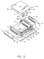
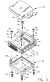
- the circuitry of Figure 1 is mounted on a printed circuit board 32, with the SIDACtor elements 20, 22, 24 (not shown in Figures 2 and 3) mounted beneath the fuse elements 14, 16.
- the printed circuit board 32 is a multilayer board having a ground plane.
- the terminal 30 of the protective network 18 is connected to that ground layer.
- Suitable traces connect a first end of the fuse elements 14, 16 to contacts in the connector 10 and suitable traces connect the second ends of the fuse elements 14, 16 to appropriate contacts in the connector 12.
- suitable traces make the connections between the SIDACtor elements 20, 22, 24 and connect the SIDACtor elements 20, 22 to the fuse elements 14, 16, respectively.
- At each of the four corners of the circuit board 32 there is a mounting hole (not shown), at least one of which is lined with conductive material (e.g., solder) which is connected to the ground plane.
- the connectors 10, 12 are mounted to the circuit board 32, in a conventional manner, and have their contacts connected to the circuitry on the board 32 as shown in Figure 1.
- the connector 10 is matable with the connector 36 which terminates the cable 38.
- the cable 38 has its other end connected to the primary lightning protection for the transmission line-pairs entering a building.
- the connector 12 is matable with the connector 40 terminating the cable 42.
- the cable 42 has its other end connected to telecommunications equipment within the building and can be substantially thinner than the cable 38, since there is another level of protection for the line-pairs contained in the cable 42.
- Each of the connectors 10, 12 is formed at its ends with a flat flange 44 having a mounting hole 46 therethrough.
- the mounting holes 46 are in registration with the mounting holes of the printed circuit board 32 when the connectors 10, 12 are mounted to the printed circuit board 32.
- a rivet 48 passes through each set of mounting holes and makes contact with the conductive material lining the mounting hole of the printed circuit board 32. The head of the rivet 48 surrounds the mounting hole 46 and overlies the flat flange 44.
- the protective network assembly is contained within an insulative housing.
- the housing has a bottom part 50 and a cover 52.
- the bottom part 50 has a floor 54 and four upstanding walls 56, 58, 60, 62, so dimensioned that the printed circuit board 32 fits closely therein with the mating faces of the connectors 10, 12 extending over the walls 56, 60, respectively.
- the floor 54 has mounting holes 64 in its four corners which are in registration with the mounting holes 34 of the printed circuit board 32 and the mounting holes 46 of the connectors 10, 12.
- the walls 58, 62 are formed with projections 66 and upwardly extending resilient latch fingers 68. The distal ends of the latch fingers 68 have apertures 70 therein.
- the housing cover 52 has a roof 72 and four downwardly depending side walls 74, 76, 78, 80, and is sized and shaped so that it covers the circuit elements on the printed circuit board 32 but leaves the connectors 10, 12 exposed.
- the side walls 76, 80 are each formed with a projection 82 and a downwardly depending resilient latch finger 84.
- Each of the latch fingers 84 has an aperture 86 at its distal end. The size, configuration, and placement of the projections 66, 82, the latch fingers 68, 84 and the apertures 70, 86 are such that the bottom part 50 and the cover 52 can be snapped together, with the projections 66 entering the apertures 86 and the projections 82 entering the apertures 70.
- each of the female screw locks 90 has a head 94 which engages the head of a respective rivet 48 when the body of that female screw lock 90 is passed through the mounting hole of the connector, printed circuit board and housing bottom part.
- Each female screw lock 90 has a threaded hole 95 on the head 94 and screw threads 91.
- Appropriately registered mounting holes are provided in the chassis 88 and then the entire assembly is secured to the chassis 88 by placing the distal threaded ends of the female screw lock 90 through those chassis mounting holes and securing the female screw lock 90 by means of the washers and nuts 92. In addition to securing the assembly to the chassis 88, this completes the grounding path from the ground plane of the circuit board 32 to the chassis 88.
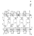
- Figure 4 illustrates how a plurality (illustratively four) of adaptor assemblies can be stacked and secured to the chassis 88 by means of the threads 91 of one female screw lock 90 engaging the threaded hole 95 on the head 94 of another female screw lock 90, thereby securing one assembly to the assembly immediately therebelow.
Landscapes
- Engineering & Computer Science (AREA)
- Microelectronics & Electronic Packaging (AREA)
- Emergency Protection Circuit Devices (AREA)
- Details Of Connecting Devices For Male And Female Coupling (AREA)
- Structure Of Telephone Exchanges (AREA)
Claims (8)
- Baugruppe für die Montage an ein geerdetes Chassis, die aufweist: ein Gehäuse; dritte und vierte Kabelverbinder (10, 12), die auf eine Leiterplatte (32) mit Abstand montiert sind, wobei der dritte Kabelverbinder (10) mit einem Mehrleiterkabel in Eingriff kommen kann, das mittels eines ersten Kabelverbinders (36) angeschlossen ist, und wobei der vierte Kabelverbinder (12) mit einem Mehrleiterkabel in Eingriff kommen kann, das mittels eines zweiten Kabelverbinders (40) angeschlossen ist, wobei die Leiterplatte (32) eine Erdungsfläche und ein Überspannungsstoßschutznetz (18) darauf aufweist, wobei das Schutznetz (18) mit Leitern der Mehrleiterkabel gekoppelt und zwischen Leitern des ersten Kabelverbinders und Leitern des zweiten Kabelverbinders angeordnet ist; eine elektrische Kopplung zwischen Schutznetz (18) und Erdungsfläche, worin die Baugruppe eine elektrische Kopplungseinrichtung für das Erden umfaßt, dadurch gekennzeichnet, daß die elektrische Kopplungseinrichtung zwischen der Erdungsfläche und dem Chassis angeordnet ist, wenn sie auf das Chassis montiert ist, wobei die elektrische Kopplungseinrichtung bewirkt, daß eine Vielzahl von Gehäusen physikalisch mit den Erdungsflächen einer jeden elektrisch gekoppelten Baugruppe übereinandergestapelt werden kann.
- Baugruppe nach Anspruch 1, bei der ein entsprechendes Schutznetz (18) mit jedem Übertragungsleitungspaar verbunden ist.
- Baugruppe nach Anspruch 1, die außerdem aufweist: eine Vielzahl von rückstellbaren Sicherungselementen (14, 16), wobei jedes der Sicherungselemente (14, 16) einem entsprechenden Leiter des ersten Mehrleiterkabels und einem entsprechenden Leiter des zweiten Mehrleiterkabels entspricht;eine Einrichtung für das Montieren der Sicherungselemente auf die Leiterplatte; undeine Einrichtung für das Verbinden der Sicherungselemente mit den dritten und vierten Kabelverbindern (10, 12), so daß jedes der Sicherungselemente (14, 16) mit den entsprechenden Leitern der ersten und zweiten Kabel in Reihe ist, die mit der Baugruppe verbunden sind.
- Baugruppe nach Anspruch 1, die außerdem ein isolierendes Gehäuse aufweist, das so ausgelegt ist, daß es die Leiterplatte (32) aufnimmt und die dritten und vierten Kabelverbinder freilegt.
- Baugruppe nach Anspruch 1-4, bei der die Leiterplatte (32) mit mindestens einem Montageloch versehen ist;das Gehäuse mit mindestens einem Montageloch (64) in Ausrichtung mit dem mindestens einem Montageloch der Leiterplatte (32) versehen ist; unddas Chassis (88) mit mindestens einem Montageloch versehen ist;wobei die Baugruppe außerdem aufweist: mindestens ein leitendes Montageelement (48), das sich durch das mindestens eine Montageloch der Leiterplatte, des Gehäuses und des Chassis erstreckt;eine Einrichtung für das elektrische Koppeln der Erdungsfläche der Leiterplatte mit dem mindestens einem Montageelement (48); undeine Einrichtung (90) für das elektrische Koppeln des Chassis (88) mit dem mindestens einem Montageelement (48).
- Baugruppe nach Anspruch 5, bei der die Kopplungseinrichtung für die Erdungsfläche der Leiterplatte ein leitendes Material in elektrischem Kontakt mit der Erdungsfläche umfaßt, wobei das leitende Material das mindestens eine Montageloch der Leiterplatte auskleidet.
- Baugruppe nach Anspruch 6, bei der das leitende Montageelement (48) eine leitende Schraube mit einem Kopf an einem Ende und Außengewinde am anderen Ende umfaßt, wobei die Schraube mit dem leitenden Material in elektrischem Kontakt ist, wenn sich die Schraube durch das Montageloch der Leiterplatte erstreckt.
- Baugruppe nach Anspruch 1, bei der das Schutznetz aufweist:einen ersten in zwei Richtungen wirkenden spannungsempfindlichen Schalter (20) mit einer ersten und zweiten Leitung;einen zweiten in zwei Richtungen wirkenden spannungsempfindlichen Schalter (22) mit einer dritten und vierten Leitung;einen dritten in zwei Richtungen wirkenden spannungsempfindlichen Schalter (24) mit einer fünften und sechsten Leitung;eine Einrichtung für das Verbinden der ersten Leitung mit der ersten Anschlußklemme (26) des Schutznetzes;eine Einrichtung für das Miteinanderverbinden der zweiten, dritten und fünften Leitung;eine Einrichtung für das Verbinden der vierten Leitung mit der zweiten Anschlußklemme (28) des Schutznetzes; undeine Einrichtung für das Verbinden der sechsten Leitung mit der dritten Anschlußklemme (30) des Schutznetzes.
Applications Claiming Priority (3)
| Application Number | Priority Date | Filing Date | Title |
|---|---|---|---|
| US515181 | 1995-08-11 | ||
| US08/515,181 US5563761A (en) | 1995-08-11 | 1995-08-11 | Transient voltage surge protection assembly for telecommunications lines |
| PCT/US1996/013088 WO1997007569A1 (en) | 1995-08-11 | 1996-08-12 | Transient voltage surge protection assembly for telecommunications lines |
Publications (2)
| Publication Number | Publication Date |
|---|---|
| EP0843908A1 EP0843908A1 (de) | 1998-05-27 |
| EP0843908B1 true EP0843908B1 (de) | 1999-06-23 |
Family
ID=24050276
Family Applications (1)
| Application Number | Title | Priority Date | Filing Date |
|---|---|---|---|
| EP96928848A Expired - Lifetime EP0843908B1 (de) | 1995-08-11 | 1996-08-12 | Überspannungsschutzvorrichtung für fernmeldeleitungen |
Country Status (5)
| Country | Link |
|---|---|
| US (1) | US5563761A (de) |
| EP (1) | EP0843908B1 (de) |
| JP (1) | JP3779326B2 (de) |
| DE (1) | DE69603027T2 (de) |
| WO (1) | WO1997007569A1 (de) |
Families Citing this family (18)
| Publication number | Priority date | Publication date | Assignee | Title |
|---|---|---|---|---|
| US5892659A (en) * | 1995-12-12 | 1999-04-06 | The Whitaker Corporation | Retention system for solenoid coils |
| US5841620A (en) * | 1995-12-22 | 1998-11-24 | Illinois Tool Works Inc. | Transmission bandwidth extender/category 5 protector |
| US5706160A (en) * | 1995-12-22 | 1998-01-06 | Illinois Tool Works, Inc. | Transmission bandwidth extender/category 5 protector |
| KR100239514B1 (ko) * | 1996-07-29 | 2000-01-15 | 윤종용 | 전자렌지 |
| US6342998B1 (en) * | 1998-11-13 | 2002-01-29 | Leviton Manufacturing Co., Inc. | Data surge protection module |
| US6072683A (en) * | 1999-03-03 | 2000-06-06 | Illinois Tool Works Inc. | Miniaturized category 5 protection circuit |
| US6482040B1 (en) | 2000-06-01 | 2002-11-19 | Dennis L. Brooks | Electrical systems using linear fusing |
| US6716065B1 (en) | 2000-06-01 | 2004-04-06 | Leftek International, Llc | Electrical systems with paired bus connectors |
| US6795289B2 (en) * | 2002-01-11 | 2004-09-21 | Illinois Tool Works Inc. | Dual sneak current protector |
| US7408757B2 (en) * | 2005-03-29 | 2008-08-05 | Diversified Technology Group, Inc. | Low voltage surge protectors with ground shield |
| US7429178B2 (en) * | 2006-09-12 | 2008-09-30 | Samtec, Inc. | Modular jack with removable contact array |
| WO2009005521A1 (en) * | 2007-06-29 | 2009-01-08 | Brooks Dennis L | Fused power intercept |
| US20090001812A1 (en) * | 2007-06-29 | 2009-01-01 | Brooks Dennis L | Fused Power Intercept |
| US7701689B1 (en) | 2008-01-31 | 2010-04-20 | Adtran, Inc. | Protector block assembly for providing surge protection in telecommunication systems |
| JP2010244862A (ja) * | 2009-04-07 | 2010-10-28 | Toshiba Corp | 電子部品取付構造 |
| JP2011186540A (ja) * | 2010-03-04 | 2011-09-22 | Toshiba Tec Corp | インタフェース装置及び電子装置 |
| KR102456119B1 (ko) * | 2015-08-06 | 2022-10-19 | 삼성전자 주식회사 | 전자장치에 전원을 공급하는 전원 인렛 소켓 |
| EP3472571B1 (de) * | 2016-06-20 | 2022-03-02 | Koninklijke Philips N.V. | Medizinische kupplungseinheit und sensorseitiger verbinder |
Family Cites Families (17)
| Publication number | Priority date | Publication date | Assignee | Title |
|---|---|---|---|---|
| SE414357B (sv) * | 1978-08-17 | 1980-07-21 | Asea Ab | Overspenningsskydd for skydd av halvledarkomponenter av lageffekttyp |
| US4392701A (en) * | 1980-07-16 | 1983-07-12 | Amp Incorporated | Tap connector assembly |
| US4449156A (en) * | 1982-09-24 | 1984-05-15 | Porta Systems Corp. | Telephone central office gas tube replacement protector |
| US4477857A (en) * | 1982-12-27 | 1984-10-16 | Gte Network Systems Corporation | Printed circuit fuse |
| US4661878A (en) * | 1984-01-25 | 1987-04-28 | Motorola Inc. | Overvoltage protection circuit |
| JPS62206776A (ja) * | 1986-03-05 | 1987-09-11 | 株式会社村田製作所 | フイルタコネクタ |
| US4772225A (en) * | 1987-11-19 | 1988-09-20 | Amp Inc | Electrical terminal having means for mounting electrical circuit components in series thereon and connector for same |
| US4894630A (en) * | 1987-11-28 | 1990-01-16 | Nec Home Electronics Ltd. | Conversion adapter |
| US4862311A (en) * | 1988-04-12 | 1989-08-29 | Reliance Comm/Tec Corporation | Overvoltage protector for use with data cables |
| US4799901A (en) * | 1988-06-30 | 1989-01-24 | Pirc Douglas J | Adapter having transient suppression protection |
| US4950169A (en) * | 1989-03-13 | 1990-08-21 | Pc Industries, Inc. | Universal cable connector for electronic devices |
| US5034846A (en) * | 1989-09-11 | 1991-07-23 | Donald E. Hodge | Plug protector |
| US5208723A (en) * | 1990-08-20 | 1993-05-04 | Texas Instruments Incorporated | Solid state electronic protector with pressure release |
| JPH04209480A (ja) * | 1990-12-03 | 1992-07-30 | Murata Mfg Co Ltd | コネクタ |
| GB2267588B (en) * | 1992-06-06 | 1996-03-20 | Motorola Inc | FIFO memory system |
| US5359657A (en) * | 1992-06-08 | 1994-10-25 | Oneac Corporation | Telephone line overvoltage protection apparatus |
| CA2095500C (en) * | 1992-06-08 | 1997-09-23 | Dimitris Jim Pelegris | Telephone line overvoltage protection method and apparatus |
-
1995
- 1995-08-11 US US08/515,181 patent/US5563761A/en not_active Expired - Lifetime
-
1996
- 1996-08-12 EP EP96928848A patent/EP0843908B1/de not_active Expired - Lifetime
- 1996-08-12 WO PCT/US1996/013088 patent/WO1997007569A1/en not_active Ceased
- 1996-08-12 JP JP50940797A patent/JP3779326B2/ja not_active Expired - Fee Related
- 1996-08-12 DE DE69603027T patent/DE69603027T2/de not_active Expired - Fee Related
Also Published As
| Publication number | Publication date |
|---|---|
| US5563761A (en) | 1996-10-08 |
| WO1997007569A1 (en) | 1997-02-27 |
| JPH11510950A (ja) | 1999-09-21 |
| EP0843908A1 (de) | 1998-05-27 |
| DE69603027T2 (de) | 2000-01-05 |
| DE69603027D1 (de) | 1999-07-29 |
| JP3779326B2 (ja) | 2006-05-24 |
Similar Documents
| Publication | Publication Date | Title |
|---|---|---|
| US5563761A (en) | Transient voltage surge protection assembly for telecommunications lines | |
| EP0094173B1 (de) | Elektrischer Verbinder mit gemeinsamem Verbindungselement | |
| US4889497A (en) | Shielded electrical connector | |
| KR950007425B1 (ko) | 전기 커넥터 | |
| CA1208728A (en) | Electrical plug connector and receptacle therefor | |
| EP0487893B1 (de) | Modularer Abzweig-Steckverbinder | |
| US4490775A (en) | Universal programmable interface | |
| US5788521A (en) | Modular surge protection system with interchangeable surge protection modules | |
| US5823810A (en) | Safety connector | |
| US4412715A (en) | Modular electrical plug incorporating conductive path | |
| US5340333A (en) | Shielded modular adapter | |
| EP0456396A2 (de) | Elektrischer Verbinder | |
| US5509812A (en) | Cable tap assembly | |
| US5662483A (en) | Surge voltage preventing D-sub connector | |
| US4610493A (en) | Electrical connector block | |
| US6290543B1 (en) | Telephone adaptor | |
| US5964614A (en) | Connector with built-in safety feature | |
| CN1757242A (zh) | 电信模块和至少一个保护插头的组件 | |
| US6134093A (en) | Category 5/25-pair protector | |
| JP2001230022A (ja) | 遮蔽ケーブル用ケーブルコネクタ | |
| US6511327B1 (en) | Simplified network interface device | |
| US5755598A (en) | Electrical connectors | |
| US6540534B2 (en) | Telephone wiring interconnect apparatus and method | |
| US5487675A (en) | Integrated protector and modular jack | |
| JPS5873297A (ja) | 通信ラインのタ−ミナル構造 |
Legal Events
| Date | Code | Title | Description |
|---|---|---|---|
| PUAI | Public reference made under article 153(3) epc to a published international application that has entered the european phase |
Free format text: ORIGINAL CODE: 0009012 |
|
| 17P | Request for examination filed |
Effective date: 19980305 |
|
| AK | Designated contracting states |
Kind code of ref document: A1 Designated state(s): DE FR GB |
|
| GRAG | Despatch of communication of intention to grant |
Free format text: ORIGINAL CODE: EPIDOS AGRA |
|
| 17Q | First examination report despatched |
Effective date: 19981105 |
|
| GRAG | Despatch of communication of intention to grant |
Free format text: ORIGINAL CODE: EPIDOS AGRA |
|
| GRAH | Despatch of communication of intention to grant a patent |
Free format text: ORIGINAL CODE: EPIDOS IGRA |
|
| GRAH | Despatch of communication of intention to grant a patent |
Free format text: ORIGINAL CODE: EPIDOS IGRA |
|
| GRAA | (expected) grant |
Free format text: ORIGINAL CODE: 0009210 |
|
| AK | Designated contracting states |
Kind code of ref document: B1 Designated state(s): DE FR GB |
|
| REF | Corresponds to: |
Ref document number: 69603027 Country of ref document: DE Date of ref document: 19990729 |
|
| ET | Fr: translation filed | ||
| PG25 | Lapsed in a contracting state [announced via postgrant information from national office to epo] |
Ref country code: FR Free format text: LAPSE BECAUSE OF NON-PAYMENT OF DUE FEES Effective date: 20000428 |
|
| PLBE | No opposition filed within time limit |
Free format text: ORIGINAL CODE: 0009261 |
|
| STAA | Information on the status of an ep patent application or granted ep patent |
Free format text: STATUS: NO OPPOSITION FILED WITHIN TIME LIMIT |
|
| 26N | No opposition filed | ||
| REG | Reference to a national code |
Ref country code: FR Ref legal event code: ST |
|
| REG | Reference to a national code |
Ref country code: GB Ref legal event code: IF02 |
|
| PGFP | Annual fee paid to national office [announced via postgrant information from national office to epo] |
Ref country code: GB Payment date: 20030826 Year of fee payment: 8 |
|
| PGFP | Annual fee paid to national office [announced via postgrant information from national office to epo] |
Ref country code: FR Payment date: 20030828 Year of fee payment: 8 |
|
| PGFP | Annual fee paid to national office [announced via postgrant information from national office to epo] |
Ref country code: DE Payment date: 20031030 Year of fee payment: 8 |
|
| PG25 | Lapsed in a contracting state [announced via postgrant information from national office to epo] |
Ref country code: GB Free format text: LAPSE BECAUSE OF NON-PAYMENT OF DUE FEES Effective date: 20040812 |
|
| PG25 | Lapsed in a contracting state [announced via postgrant information from national office to epo] |
Ref country code: DE Free format text: LAPSE BECAUSE OF NON-PAYMENT OF DUE FEES Effective date: 20050301 |
|
| GBPC | Gb: european patent ceased through non-payment of renewal fee |
Effective date: 20040812 |