EP0843952B1 - Ultraschallwandler - Google Patents
Ultraschallwandler Download PDFInfo
- Publication number
- EP0843952B1 EP0843952B1 EP97926428A EP97926428A EP0843952B1 EP 0843952 B1 EP0843952 B1 EP 0843952B1 EP 97926428 A EP97926428 A EP 97926428A EP 97926428 A EP97926428 A EP 97926428A EP 0843952 B1 EP0843952 B1 EP 0843952B1
- Authority
- EP
- European Patent Office
- Prior art keywords
- mass
- resonator
- transducer
- ultrasonic
- ultrasonic transducer
- Prior art date
- Legal status (The legal status is an assumption and is not a legal conclusion. Google has not performed a legal analysis and makes no representation as to the accuracy of the status listed.)
- Expired - Lifetime
Links
Images


Classifications
-
- B—PERFORMING OPERATIONS; TRANSPORTING
- B06—GENERATING OR TRANSMITTING MECHANICAL VIBRATIONS IN GENERAL
- B06B—METHODS OR APPARATUS FOR GENERATING OR TRANSMITTING MECHANICAL VIBRATIONS OF INFRASONIC, SONIC, OR ULTRASONIC FREQUENCY, e.g. FOR PERFORMING MECHANICAL WORK IN GENERAL
- B06B1/00—Methods or apparatus for generating mechanical vibrations of infrasonic, sonic, or ultrasonic frequency
- B06B1/02—Methods or apparatus for generating mechanical vibrations of infrasonic, sonic, or ultrasonic frequency making use of electrical energy
- B06B1/06—Methods or apparatus for generating mechanical vibrations of infrasonic, sonic, or ultrasonic frequency making use of electrical energy operating with piezoelectric effect or with electrostriction
- B06B1/0607—Methods or apparatus for generating mechanical vibrations of infrasonic, sonic, or ultrasonic frequency making use of electrical energy operating with piezoelectric effect or with electrostriction using multiple elements
- B06B1/0611—Methods or apparatus for generating mechanical vibrations of infrasonic, sonic, or ultrasonic frequency making use of electrical energy operating with piezoelectric effect or with electrostriction using multiple elements in a pile
- B06B1/0618—Methods or apparatus for generating mechanical vibrations of infrasonic, sonic, or ultrasonic frequency making use of electrical energy operating with piezoelectric effect or with electrostriction using multiple elements in a pile of piezo- and non-piezoelectric elements, e.g. 'Tonpilz'
-
- H—ELECTRICITY
- H04—ELECTRIC COMMUNICATION TECHNIQUE
- H04R—LOUDSPEAKERS, MICROPHONES, GRAMOPHONE PICK-UPS OR LIKE ACOUSTIC ELECTROMECHANICAL TRANSDUCERS; ELECTRIC HEARING AIDS; PUBLIC ADDRESS SYSTEMS
- H04R17/00—Piezoelectric transducers; Electrostrictive transducers
Definitions
- This invention relates to transducers which generate and transmit energy in the ultrasonic or megasonic ranges, and more particularly, to an transducer wherein ceramic materials, preferably silicon carbide or alumina oxide, are used as a resonator and/or substituted for metallic materials in such transducers.
- ceramic materials preferably silicon carbide or alumina oxide
- Ultrasonic transducers are used for generating and transmitting wave energy of a predetermined frequency to a liquid contained in a container. See, for example, U.S. Patent No. 3,575,383 entitled ULTRASONIC CLEANING SYSTEM, APPARATUS AND METHOD THEREFOR. Transducers of this type can be used, for example, in ultrasonic cleaning equipment. The transducer is typically mounted to the side or the underside of a container which holds liquid, or mounted in a sealed enclosure which is immersed in a liquid in a container made of metal, plastic or glass. A single transducer or a plurality of transducers are then used to energize the liquid with sonic energy. Once energized with the sonic energy, the liquid achieves cavitation.
- This type of transducer is also referred to as a "sandwich"-type transducer because it has one or more crystals sandwiched between a head mass (or front driver) and the tail mass (or rear driver).
- a sandwich-type transducer is used in applications such as plastic welding, wire bonding, cataract and other medical surgical devices, among others.
- a conventional transducer is illustrated in Figure 1 and includes a rectangular base 1, a pair of electrodes 2a and 2b, a piezoelectric crystal 3, an insulator 4, a reflector 5, washers 6 and a bolt 7.
- the conventional transducer when energized by a high frequency power source, the conventional transducer produces weak vibrations in the 20 to 100 kHz frequency range.
- the conventional transducer also evidences a tendency to shift in frequency by +/- 3 kHz due to various external factors. This shift requires periodically adjusting the frequency of the oscillatory circuit which energizes the transducers in order to match the shift.
- US-A-4,633,119 discloses an ultrasonic transducer for generating and transmitting ultrasonic energy of this type comprising a piezoelectric crystal positioned between a head mass and a tail mass.
- the object of the present invention is to provide an enhanced ultrasonic transducer with superior acoustic performance which produces stable signals at predetermined frequencies.
- the ultrasonic transducer of the invention comprises the features claimed in the characterizing part of claim 1.
- the present invention is an enhanced ultrasonic transducer for generating and transmitting ultrasonic wave energy of a predetermined frequency to the surface of an object.
- a resonator is inserted between the head mass and the piezoelectric crystal.
- the resonator is made from a ceramic material having an acoustic velocity equal to or greater than the object, preferably a material such as silicon carbide or alumina oxide.
- the head mass and tail mass are also made from ceramic materials.
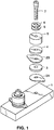
- the transducer includes a base or head mass 11, a resonance enhancing disc or resonator 12, electrodes 13a and 13b, a piezoelectric crystal 14, an insulating member 15, a reflector or tail mass 16, washers 17, a bolt 18, and phenolic insert 19.
- the head mass 11 is typically cylindrical and made of a suitable metal, such as aluminum or stainless steel.
- the head mass 11 is suitable for attachment to the surface of a container which holds liquid, such as a cleaning tank.
- the resonator 12 can be made of material including, but not limited to, aluminum, ceramic, stainless steel or leaded steel.
- the resonator material should be adapted to readily transmit ultrasonic energy. More specifically, the resonator material will have transmission characteristics, such as acoustic velocity, which are greater or equal to the adjacent mass or object in order to gain the advantage of resonance enhancement. That is, the resonator must be located between the piezoelectric crystals and surface of the object that the sound will be transmitted through, and the resonator must have the same or higher acoustic transmission velocity than the object.
- the resonator 12 be made from ceramic materials, and alumina oxide and silicon carbide are most preferred.
- alumina oxide and silicon carbide are already identified in the art and the appropriate selection of materials for use in the assemblies according to the present invention can readily be made by referring to, for example, Selfridge, Approximate Material Properties in Isotropic Materials, ISEE Transactions on Sonics and Ultrasonics, Vo. SU-32, No. 3, May 1985 , which is incorporated herein by reference.
- the electrodes 13a and 13b are typically a conductive metal such as aluminum, brass or stainless steel.
- the piezoelectric crystal 14 is typically made from lead zirconate titanate and, in one embodiment, ranges from 1.25 cm to 10.16 cm (0.50 to 4.00 inches) in diameter and 0.25 cm to 1.25 cm (0.10-0.50 inches) thick.
- the insulator 15 is a common dielectric.
- the metal reflector or tail mass 16 is typically cylindrical in shape and made of steel or leaded steel, like the head mass.
- the torque pressure is between 230.49 to 345.74 cm-kg (200 to 300 inch-pounds) for low power applications (5 to 25 watts), and between 41.49 to 69.15 m-kg (300 to 500 foot-pounds) for high power applications (up to 3000 watts).
- the thickness of the base 11, the resonator 12 and the reflector 16 are selected as an integral multiple of one quarter of the wavelength ( ⁇ /4) of the longitudinal sound vibrations in the medium.
- the insertion of the resonator 12 in between the piezoelectric crystal 14 and the base 11 of the transducer increases the intensity of the resonant frequency signals by 30 to 40 percent. Further, the periodical shift in frequency is diminished, and the temperature of the piezoelectric crystals is stabilized.
- the insertion of the resonator 12 also results in new resonant frequencies emerging in lieu of or in addition to the original resonant frequencies. For example, by inserting a 0.51 cm (0.20 inch) alumina ceramic resonator in the transducer stack, frequencies of 59 kHz, 101 kHz, 160 kHz emerged in lieu of 46 kHz, 122 kHz and 168 kHz.
- the substitution of resonators made from materials like stainless steel, aluminum and paramagnetic leaded steel produced similar results.
- resonators made from both ceramics and metals increased the intensity of all the original resonant frequencies by about 30 to 60 percent, as measured by the decrease in the piezoelectric impedance (ohms) in the new transducer assemblies.
- This enhancement greatly increases the efficiency of an ultrasonic transducer and allows it to produce stable predetermined frequency signals.
- a 40 kHz transducer can be modified to a 196 kHz transducer without any reduction in the vertical or horizontal dimensions of the crystal. In one test, we found that an enhanced 40 kHz crystal created more pressure at 122 kHz than at its original natural frequency of 40 kHz.
- a resonance enhancing disc made of a polymeric material did not function to increase the intensity of the original resonant frequencies as did the discs made of metals and ceramics.
- materials such as high density teflon attenuate, rather than transmit, ultrasonic energy.
- those materials which will be useful as resonance enhancing disks would not encompass such attenuating materials, but would include any material which functions to increase the intensity of the original resonant frequencies.
- the resonator made from a ceramic material which is selected to have sound transmission characteristics equal to or better than the adjacent mass (i.e. the transducer or other metallic or quartz substance that sound is transmitted through to perform its intended function)
- the following advantages are attained: (1) the clarity of the sound is enhanced; (2) the frequency can be raised to a higher resident frequency (as much as 500% higher); (3) the impedance level is lowered thereby improving the transmission of sound; and (4) the power generated by the piezoelectric crystal is the same as if the frequency had not been moved.
- ceramic materials are substituted for metallic materials in a transducer stack thereby resulting in an enhanced device having superior acoustical performance, as will now be described in more detail.
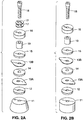
- a transducer in accord with the present embodiment is similar to that illustrated in Figure 2a , except that the washers 17 are eliminated.
- the head mass and tail mass are made from a ceramic material, preferably silicon carbide or alumina oxide.
- resonator 12 in the stack, which may also be made from ceramic material such as alumina oxide or silicon carbide.
- ceramic material such as alumina oxide or silicon carbide.
- Ceramics such as alumina oxide and silicon carbide can provide better flatness, and can meet or exceed the requirements for strength and durability of the metals and still yield improved acoustical performance, as shown by the relative acoustical properties of selected materials listed in Table 1: TABLE 1 Material Acoustical Index Metals Aluminum 6.42 Stainless steel 5.79 Titanium 6.10 Ceramics Aluminum oxide 10.52 Silicon carbide 13.06
- a 0.51 cm (0.2 inch) resonator is made from silicon carbide, and inserted in the stack in place of one made from aluminum, the stack would require removal of 1.03 cm (0.4068 inches) of aluminum.
- you converted a 2.54 cm (1 inch) aluminum head mass in its entirety to silicon carbide the height of the head mass becomes 1 + (13.06 + 6.42) a 1.25 cm (0.4916 inches).
- the tail mass likewise is converted through the use of the appropriate acoustical index.
- the entire transducer or transmitting device will show improvement if all parts are made from ceramics having superior acoustical properties than the metals they replace.
- Silicon carbide is a superior ceramic for building all parts of transducers or devices to transmit ultrasonic sound. Silicon carbide is flatter, harder (except for diamonds), more durable and acoustically superior relative to other known metals or materials, or ceramics. Silicon carbide can be used as a resonator, head mass, tail mass, or vessel of transmission as follows: (1) as a resonating vessel to hold liquid that is being excited ultrasonically for cleaning, rinsing, degreasing, coating, processing and etc.; (2) as the transmitting device with ultrasonic liquid processors; (3) as the capillary or wedge used with an ultrasonic wire or wedge bonding machine; (4) as a horn to receive the acoustical signals from a plastic assembly or welding machine converter mechanism; (5) as a triggering device to detonate a missile, torpedo, or other explosive device fired with ultrasonics; or (6) as a transmitter of sound for ultrasonic welding or bonding.
- Silicon carbide is superior in acoustical properties to other ceramics used in wire-bonding and wedge bonding which get their energy from ultrasonics: (1) it is superior for capillary design based on its 13.06 acoustical index rating as compared with aluminum oxide (10.52); and (2) it is superior to tungsten carbide (11.0) as used for wedge bonding.
- Figures 3a and 3b illustrate an ultrasonic cleaning transducer involving 3,000 to 5,000 watts in a single group of transducers.
- Figure 2a illustrates the signal generated by a 68 kHz stacked transducer having metal components
- Figure 2b illustrates the signal generated by a 68 kHz stacked transducer having ceramic components. Note the sharp peak signal of the ceramic transducer stack as compared to the metal stack. Further, the impedance fell from 84.613 to 37.708 when ceramics were substituted for metals. Lower impedance is associated with better transmission of sound and greater efficiency.
- Figures 4a and 4b Another example of the improvement obtained when ceramics are substituted for metals in low power transducer applications (10 to 15 watts) is shown in Figures 4a and 4b.
- Figure 4a shows the signal generated by a transducer stack having metal components
- Figure 4b shows the signal generated by a transducer stack having ceramic components. It can be seen the ceramic stack pictured in Figure 3b produces two usable frequencies, namely 80 kHz with an impedance of 193 ohms, and 164 kHz with an impedance of 127 ohms.
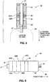
- FIG. 5 shows an arrangement which includes a transducer stack 30 for use in ultrasonic plastic welding.
- a transducer stack 30 for use in ultrasonic plastic welding.
- this stack there is a ceramic tail mass or back driver 31, piezoelectric crystals 32a and 32b, an aluminum electrode 33 positioned between the crystals, a ceramic resonator 34 and a ceramic head mass or front driver 35.
- the transducer 30 is connected to a welding horn 36 by bolt 37 such that the head mass 35 is in contact with the welding horn.
- the welding horn 36 interfaces with the parts being ultrasonically bonded.
- This device is also generally known as a converter, and can handle high power plastic welding requirements up to 3000 watts.
- FIG. 6 shows a transducer stack 40 for use in wire bonding.
- this stack there is a ceramic tail mass or back driver 41, piezoelectric crystals 42a, 42b and 42c, interlocking brass electrodes 43a and 43b, a ceramic resonator 44 and a ceramic head mass or front driver 45.
- the transducer 40 is connected to a horn 48 by screw or bolt 47 in the same manner as the previous embodiment such that the head mass 45 is in contact with the horn.
- This device is also generally known as a motor for wire bonding, and can handle low power bonding requirements of approximately 10 to 15 watts.
- this invention relates to an improved ultrasonic transducer for generating and transmitting ultrasonic wave energy of a predetermined frequency.
- the improvement resides in the use of a resonator and/or the substitution of ceramic material, preferably silicon carbide or alumina oxide, for metal components in a transducer stack.
- the required thicknesses for elements in a transducer stack may be readily identified for optimal performance, and the specific geometries required for specific applications can be readily determined.
Landscapes
- Engineering & Computer Science (AREA)
- Mechanical Engineering (AREA)
- Physics & Mathematics (AREA)
- Acoustics & Sound (AREA)
- Signal Processing (AREA)
- Transducers For Ultrasonic Waves (AREA)
- Apparatuses For Generation Of Mechanical Vibrations (AREA)
- Cleaning By Liquid Or Steam (AREA)
- Measurement Of Velocity Or Position Using Acoustic Or Ultrasonic Waves (AREA)
- Surgical Instruments (AREA)
- Ultra Sonic Daignosis Equipment (AREA)
- Investigating Or Analyzing Materials By The Use Of Ultrasonic Waves (AREA)
Claims (11)
- Ultraschallwandler (10) zum Erzeugen und Übertragen von Ultraschallenergie; wobei der Wandler (10) umfasst:einen piezoelektrischen Kristall (14), der betreibbar ist, um Ultraschallenergie in Reaktion auf ein angelegtes elektrisches Signal zu erzeugen,eine Kopfmasse (11), die an einer Seite des piezoelektrischen Kristalls (14) positioniert ist, undeine Endmasse (16), die an einer gegenüberliegenden Seite des piezoelektrischen Kristalls (14) positioniert ist,dadurch gekennzeichnet, dass er ein Resonator (12) umfasst, der zwischen der Kopfmasse (11) und dem piezoelektrischen Kristall (14) positioniert ist, wobei der Resonator aus einem Keramikmaterial zusammengesetzt ist, wobei der Resonator (12) Ultraschallenergie, die vom piezoelektrischen Kristall (14) erzeugt wurde, an die Kopfmasse (11) übertragt, und wobei der Resonator (12) eine höhere akustische Übertragungsgeschwindigkeit als die Kopfmasse (11) aufweist.
- Ultraschallwandler nach Anspruch 1, dadurch gekennzeichnet, dass das Keramikmaterial des Resonators (12) Siliciumcarbid oder Aluminiumoxid ist.
- Ultraschallwandler nach Anspruch 1, dadurch gekennzeichnet, dass er ferner einen Isolator (15) umfasst, der aus einem Keramikmaterial zusammengesetzt und zwischen der Endmasse (16) und dem piezoelektrischen Kristall (14) positioniert ist.
- Ultraschallwandler nach Anspruch 3, dadurch gekennzeichnet, dass das Keramikmaterial des Isolators (15) Siliciumcarbid oder Aluminiumoxid ist.
- Ultraschallwandler nach Anspruch 1, dadurch gekennzeichnet, dass der Resonator (12) mit der Kopfmasse (11) in Kontakt steht.
- Ultraschallwandler nach Anspruch 1, dadurch gekennzeichnet, dass die Kopfmasse (11) und die Endmasse (16) aus einem Keramikmaterial zusammengesetzt sind.
- Ultraschallwandler nach Anspruch 6, dadurch gekennzeichnet, dass das Keramikmaterial der Kopfmasse (11) und der Endmasse (16) Siliciumcarbid oder Aluminiumoxid ist.
- Ultraschallwandler nach Anspruch 1, dadurch gekennzeichnet, dass er ferner eine erste Elektrode (13A), die zwischen der Kopfmasse (11) und dem piezoelektrischen Kristall (14) positioniert ist, und eine zweite Elektrode (13B) umfasst, die zwischen der Endmasse (16) und dem piezoelektrischen Kristall (14) positioniert ist.
- Ultraschallwandler nach Anspruch 1, dadurch gekennzeichnet, dass er umfasst:zumindest zwei piezoelektrische Kristalle (32A, 32B), die zwischen der Kopfmasse (35) und der Endmasse (31) positioniert sind, undElektroden (33), die mit den zumindest zwei piezoelektrischen Kristallen (32A, 32B) verbunden sind.
- Ultraschallwandler nach Anspruch 1, dadurch gekennzeichnet, dass er ferner Mittel (18) zum Komprimieren der Kopfmasse (11), des Resonators (12), des piezoelektrischen Kristalls (14) und der Endmasse (16) umfasst.
- Ultraschallwandler nach Anspruch 10, dadurch gekennzeichnet, dass die Kopfmasse (11) ein Gewindeloch aufweist, wobei der Resonator (12), der piezoelektrische Kristall (14) und die Endmasse (16) jeweils ein Loch aufweisen, wobei die Kopfmasse (11), der Resonator (12), der piezoelektrische Kristall (14) und die Endmasse (16) in einem Stapel angeordnet sind, und wobei die Mittel zum Komprimieren einen Bolzen (18) umfassen, der sich durch die Löcher der Endmasse (16), des piezoelektrischen Kristalls (14) und des Resonators (12) erstreckt und in das Gewindeloch der Kopfmasse (11) geschraubt ist, um den Stapel an der Kopfmasse (11) zu befestigen.
Applications Claiming Priority (9)
| Application Number | Priority Date | Filing Date | Title |
|---|---|---|---|
| US792568 | 1991-11-15 | ||
| US08/644,843 US5748566A (en) | 1996-05-09 | 1996-05-09 | Ultrasonic transducer |
| US644843 | 1996-05-09 | ||
| US79256897A | 1997-01-31 | 1997-01-31 | |
| US3896197P | 1997-02-24 | 1997-02-24 | |
| US38961P | 1997-02-24 | ||
| US3922897P | 1997-02-28 | 1997-02-28 | |
| US39228P | 1997-02-28 | ||
| PCT/US1997/007845 WO1997042790A1 (en) | 1996-05-09 | 1997-05-09 | Ultrasonic transducer |
Publications (3)
| Publication Number | Publication Date |
|---|---|
| EP0843952A1 EP0843952A1 (de) | 1998-05-27 |
| EP0843952A4 EP0843952A4 (de) | 2003-03-26 |
| EP0843952B1 true EP0843952B1 (de) | 2012-05-02 |
Family
ID=27488573
Family Applications (1)
| Application Number | Title | Priority Date | Filing Date |
|---|---|---|---|
| EP97926428A Expired - Lifetime EP0843952B1 (de) | 1996-05-09 | 1997-05-09 | Ultraschallwandler |
Country Status (10)
| Country | Link |
|---|---|
| US (1) | US5998908A (de) |
| EP (1) | EP0843952B1 (de) |
| JP (1) | JP2001526006A (de) |
| KR (1) | KR100732831B1 (de) |
| CN (1) | CN1263348C (de) |
| AT (1) | ATE556543T1 (de) |
| AU (1) | AU732733B2 (de) |
| CA (1) | CA2226724C (de) |
| MX (1) | MX9800303A (de) |
| WO (1) | WO1997042790A1 (de) |
Families Citing this family (69)
| Publication number | Priority date | Publication date | Assignee | Title |
|---|---|---|---|---|
| US6016821A (en) | 1996-09-24 | 2000-01-25 | Puskas; William L. | Systems and methods for ultrasonically processing delicate parts |
| US5834871A (en) | 1996-08-05 | 1998-11-10 | Puskas; William L. | Apparatus and methods for cleaning and/or processing delicate parts |
| US7336019B1 (en) | 2005-07-01 | 2008-02-26 | Puskas William L | Apparatus, circuitry, signals, probes and methods for cleaning and/or processing with sound |
| US6822372B2 (en) | 1999-08-09 | 2004-11-23 | William L. Puskas | Apparatus, circuitry and methods for cleaning and/or processing with sound waves |
| US7211928B2 (en) | 1996-08-05 | 2007-05-01 | Puskas William L | Apparatus, circuitry, signals and methods for cleaning and/or processing with sound |
| US6313565B1 (en) | 2000-02-15 | 2001-11-06 | William L. Puskas | Multiple frequency cleaning system |
| US7211927B2 (en) | 1996-09-24 | 2007-05-01 | William Puskas | Multi-generator system for an ultrasonic processing tank |
| US6370086B2 (en) * | 1999-03-15 | 2002-04-09 | Shih-Hsiung Li | Ultrasound sensor for distance measurement |
| US6278218B1 (en) * | 1999-04-15 | 2001-08-21 | Ethicon Endo-Surgery, Inc. | Apparatus and method for tuning ultrasonic transducers |
| US20030130657A1 (en) * | 1999-08-05 | 2003-07-10 | Tom Curtis P. | Devices for applying energy to tissue |
| US7467945B2 (en) * | 2004-09-10 | 2008-12-23 | S.C. Johnson & Son, Inc. | Candle assembly and fuel element therefor |
| EP1149637B1 (de) * | 2000-04-28 | 2007-02-28 | Kao Corporation | Horn für eine Vorrichtung zur Ultraschallreinigung |
| DE20013827U1 (de) * | 2000-08-10 | 2001-12-20 | Kaltenbach & Voigt GmbH & Co., 88400 Biberach | Medizinisches oder dentalmedizinisches Behandlungsinstrument mit einem Werkzeugträger in Form eines Schwingstabes |
| US7019439B2 (en) | 2001-07-30 | 2006-03-28 | Blackstone-Ney Ultrasonics, Inc. | High power ultrasonic transducer with broadband frequency characteristics at all overtones and harmonics |
| US6871770B2 (en) * | 2001-10-01 | 2005-03-29 | Asm Assembly Automation Limited | Ultrasonic transducer |
| US6924585B2 (en) * | 2002-09-23 | 2005-08-02 | The Crest Group, Inc. | Sleeved ultrasonic transducer |
| US6822373B1 (en) * | 2002-11-25 | 2004-11-23 | The United States Of America As Represented By The Secretary Of The Navy | Broadband triple resonant transducer |
| US7104268B2 (en) * | 2003-01-10 | 2006-09-12 | Akrion Technologies, Inc. | Megasonic cleaning system with buffered cavitation method |
| JP2004248368A (ja) * | 2003-02-12 | 2004-09-02 | Asmo Co Ltd | 超音波モータ、及びその製造方法 |
| WO2004103014A2 (en) * | 2003-05-09 | 2004-11-25 | The Crest Group, Inc. | Advanced ceramics in ultrasonic transducerized devices |
| US7495371B2 (en) * | 2003-09-08 | 2009-02-24 | The Crest Group, Inc. | Cleaning tank with sleeved ultrasonic transducer |
| US6967149B2 (en) * | 2003-11-20 | 2005-11-22 | Hewlett-Packard Development Company, L.P. | Storage structure with cleaved layer |
| RU2267235C1 (ru) * | 2004-05-19 | 2005-12-27 | Федеральное государственное унитарное предприятие "Таганрогский завод "Прибой" | Широкополосный электроакустический преобразователь |
| JP4466236B2 (ja) * | 2004-07-01 | 2010-05-26 | 日本電気株式会社 | 送受波器 |
| US7122943B2 (en) * | 2004-09-01 | 2006-10-17 | Impulse Devices, Inc. | Acoustic driver assembly with restricted contact area |
| US7224103B2 (en) | 2004-09-01 | 2007-05-29 | Impulse Devices, Inc. | Acoustic driver assembly with recessed head mass contact surface |
| US7126256B2 (en) * | 2004-09-01 | 2006-10-24 | Impulse Devices, Inc. | Acoustic driver assembly with recessed head mass contact surface |
| US6958569B1 (en) * | 2004-09-01 | 2005-10-25 | Impulse Devices, Inc. | Acoustic driver assembly for a spherical cavitation chamber |
| US20060043840A1 (en) * | 2004-09-01 | 2006-03-02 | Impulse Devices Inc. | Acoustic driver assembly with restricted contact area |
| US7122941B2 (en) * | 2004-09-01 | 2006-10-17 | Impulse Devices, Inc. | Acoustic driver assembly with recessed head mass contact surface |
| US20070035208A1 (en) * | 2004-09-01 | 2007-02-15 | Impulse Devices Inc. | Acoustic driver assembly with restricted contact area |
| WO2006028609A2 (en) * | 2004-09-01 | 2006-03-16 | Impulse Devices, Inc. | Acoustic driver assembly with modified head mass contact surface |
| US20060043838A1 (en) * | 2004-09-01 | 2006-03-02 | Impulse Devices, Inc. | Acoustic driver assembly with restricted contact area |
| US7425791B2 (en) * | 2004-09-01 | 2008-09-16 | Impulse Devices, Inc. | Acoustic driver assembly with recessed head mass contact surface |
| US7218033B2 (en) * | 2004-09-01 | 2007-05-15 | Impulse Devices, Inc. | Acoustic driver assembly with restricted contact area |
| US7218034B2 (en) * | 2004-09-01 | 2007-05-15 | Impulse Devices, Inc. | Acoustic driver assembly with restricted contact area |
| US7425792B2 (en) * | 2004-09-01 | 2008-09-16 | Impulse Devices, Inc. | Acoustic driver assembly with restricted contact area |
| US7126258B2 (en) * | 2004-09-01 | 2006-10-24 | Impulse Devices, Inc. | Acoustic driver assembly with recessed head mass contact surface |
| US20060043835A1 (en) * | 2004-09-01 | 2006-03-02 | Impulse Devices Inc. | Acoustic driver assembly with restricted contact area |
| DE102004045575A1 (de) * | 2004-09-17 | 2006-04-06 | Hesse & Knipps Gmbh | Ultraschalltransducer mit einem in der Lagerung angeordneten Sensor |
| US20060269460A1 (en) * | 2005-05-27 | 2006-11-30 | Impulse Devices, Inc. | Hourglass-shaped cavitation chamber with spherical lobes |
| US20060269458A1 (en) * | 2005-05-27 | 2006-11-30 | Impulse Devices, Inc. | Hourglass-shaped cavitation chamber with spherical lobes |
| US20060269459A1 (en) * | 2005-05-27 | 2006-11-30 | Impulse Devices, Inc. | Hourglass-shaped cavitation chamber with spherical lobes |
| US8187545B2 (en) * | 2005-05-27 | 2012-05-29 | Impulse Devices Inc. | Hourglass-shaped cavitation chamber with spherical lobes |
| US20060269456A1 (en) * | 2005-05-27 | 2006-11-30 | Impulse Devices, Inc. | Hourglass-shaped cavitation chamber |
| WO2006138438A2 (en) * | 2005-06-15 | 2006-12-28 | Akrion, Inc. | System and method of processing substrates using sonic energy having cavitation control |
| US20070103034A1 (en) * | 2005-11-04 | 2007-05-10 | Impulse Devices Inc. | Acoustic driver assembly with increased head mass displacement amplitude |
| US7510322B2 (en) * | 2005-12-16 | 2009-03-31 | Impulse Devices, Inc. | High pressure cavitation chamber with dual internal reflectors |
| US20070138911A1 (en) * | 2005-12-16 | 2007-06-21 | Impulse Devices Inc. | Tunable acoustic driver and cavitation chamber assembly |
| US7461965B2 (en) * | 2005-12-16 | 2008-12-09 | Impulse Devices, Inc. | Cavitation chamber with flexibly mounted reflector |
| US7495370B1 (en) * | 2006-05-04 | 2009-02-24 | Lockheed Martin Corporation | Hybrid transducer |
| CN101098196B (zh) * | 2006-06-29 | 2012-02-22 | 沅龙科技股份有限公司 | 电子讯号噪声抑制器及其制造方法 |
| US10355623B1 (en) | 2006-12-07 | 2019-07-16 | Dmitriy Yavid | Generator employing piezolectric and resonating elements with synchronized heat delivery |
| US9590534B1 (en) | 2006-12-07 | 2017-03-07 | Dmitriy Yavid | Generator employing piezoelectric and resonating elements |
| US7696673B1 (en) | 2006-12-07 | 2010-04-13 | Dmitriy Yavid | Piezoelectric generators, motor and transformers |
| US20080312460A1 (en) * | 2007-06-13 | 2008-12-18 | Goodson J Michael | Multi-Frequency Ultrasonic Apparatus and Process for Producing Biofuels |
| FR2931016B1 (fr) * | 2008-05-07 | 2010-08-13 | Ixsea | Antenne acoustique a circuits imprimes integres |
| RU2402113C1 (ru) * | 2009-02-16 | 2010-10-20 | Сергей Дмитриевич Шестаков | Пьезоэлектрический излучатель плоской ультразвуковой волны |
| WO2011055317A1 (en) * | 2009-11-09 | 2011-05-12 | Koninklijke Philips Electronics N.V. | Ultrasonic hifu transducer with non - magnetic conductive vias |
| DE212015000167U1 (de) * | 2014-06-26 | 2017-03-27 | Mario Similjanic | Reifen mit Ultraschallaussendung für Wasserhohlraumbildung |
| KR20170009158A (ko) | 2015-07-15 | 2017-01-25 | 허정규 | 수중위치 추적을 위한 가변음향 송수신장치 |
| CN106140596A (zh) * | 2016-07-11 | 2016-11-23 | 杨林 | 超声波处置装置 |
| CN107913841A (zh) * | 2016-10-10 | 2018-04-17 | 上海声定科技有限公司 | 一种超声波换能器振子 |
| US11541422B2 (en) * | 2016-10-24 | 2023-01-03 | Mario Smiljanić | Ultrasonic grip system |
| WO2019186324A1 (en) * | 2018-03-24 | 2019-10-03 | RAMCHANDRAN, Shankar Trichur | Piezo crystal for an ultrasonic transducer |
| DE102018216444A1 (de) * | 2018-09-26 | 2020-03-26 | Siemens Mobility GmbH | Anregungseinheit für einen Ultraschallsender und Verfahren zur Ultraschallprüfung |
| WO2020065388A1 (en) * | 2018-09-28 | 2020-04-02 | Nidek Co., Ltd. | Ultrasonic tonometer and ultrasonic actuator |
| WO2021030694A1 (en) * | 2019-08-15 | 2021-02-18 | Cybersonics, Inc. | Ultrasound transducer and housing for same |
| CN118067951B (zh) * | 2024-04-10 | 2025-02-18 | 吉林大学 | 超声波含能材料起爆装置及超声波含能材料的起爆方法 |
Family Cites Families (17)
| Publication number | Priority date | Publication date | Assignee | Title |
|---|---|---|---|---|
| US2998535A (en) * | 1958-04-29 | 1961-08-29 | Acoustica Associates Inc | Composite electro-acoustic transducer configuration |
| US3187207A (en) * | 1960-08-08 | 1965-06-01 | Giannini Controls Corp | Transducers |
| US4219889A (en) * | 1960-09-16 | 1980-08-26 | The United States Of America As Represented By The Secretary Of The Navy | Double mass-loaded high power piezo-electric underwater transducer |
| US3575383A (en) * | 1969-01-13 | 1971-04-20 | John A Coleman | Ultrasonic cleaning system, apparatus and method therefor |
| GB1331100A (en) * | 1969-11-03 | 1973-09-19 | Crest Ultrasonics Corp | Transducer suitable for use with ultrasonic processing tanks |
| US3777189A (en) * | 1972-05-04 | 1973-12-04 | Westinghouse Electric Corp | Acoustic energy transmission device |
| US4129850A (en) * | 1973-11-12 | 1978-12-12 | Raytheon Company | Balanced transducer |
| US3937990A (en) * | 1974-05-28 | 1976-02-10 | Winston Ronald H | Ultrasonic composite devices |
| US4193009A (en) * | 1976-01-26 | 1980-03-11 | Durley Benton A Iii | Ultrasonic piezoelectric transducer using a rubber mounting |
| JPS5850898A (ja) * | 1981-09-21 | 1983-03-25 | Nec Corp | ボルト締めランジユバン振動子 |
| JPS59229999A (ja) * | 1983-06-10 | 1984-12-24 | Matsushita Electric Ind Co Ltd | 超音波探触子の製造方法 |
| US4633119A (en) * | 1984-07-02 | 1986-12-30 | Gould Inc. | Broadband multi-resonant longitudinal vibrator transducer |
| US4602184A (en) * | 1984-10-29 | 1986-07-22 | Ford Motor Company | Apparatus for applying high frequency ultrasonic energy to cleaning and etching solutions |
| SE465946B (sv) * | 1986-09-11 | 1991-11-18 | Bengt Henoch | Anordning foer oeverfoering av elektrisk energi till elektrisk utrustning genom omagnetiska och elektriskt isolerande material |
| JPH0746694A (ja) * | 1993-07-30 | 1995-02-14 | Olympus Optical Co Ltd | 超音波トランスデューサ |
| JPH0821840A (ja) * | 1994-07-08 | 1996-01-23 | Olympus Optical Co Ltd | 医療用分析機の分注ノズル洗浄装置 |
| US5748566A (en) * | 1996-05-09 | 1998-05-05 | Crest Ultrasonic Corporation | Ultrasonic transducer |
-
1997
- 1997-05-09 US US08/853,423 patent/US5998908A/en not_active Expired - Fee Related
- 1997-05-09 CA CA002226724A patent/CA2226724C/en not_active Expired - Fee Related
- 1997-05-09 WO PCT/US1997/007845 patent/WO1997042790A1/en not_active Ceased
- 1997-05-09 KR KR1019980700225A patent/KR100732831B1/ko not_active Expired - Lifetime
- 1997-05-09 CN CNB971908249A patent/CN1263348C/zh not_active Expired - Lifetime
- 1997-05-09 AT AT97926428T patent/ATE556543T1/de active
- 1997-05-09 AU AU31198/97A patent/AU732733B2/en not_active Ceased
- 1997-05-09 EP EP97926428A patent/EP0843952B1/de not_active Expired - Lifetime
- 1997-05-09 JP JP54022397A patent/JP2001526006A/ja active Pending
-
1998
- 1998-01-09 MX MX9800303A patent/MX9800303A/es unknown
Also Published As
| Publication number | Publication date |
|---|---|
| CN1263348C (zh) | 2006-07-05 |
| AU3119897A (en) | 1997-11-26 |
| AU732733B2 (en) | 2001-04-26 |
| EP0843952A1 (de) | 1998-05-27 |
| CN1196862A (zh) | 1998-10-21 |
| CA2226724A1 (en) | 1997-11-13 |
| EP0843952A4 (de) | 2003-03-26 |
| CA2226724C (en) | 2007-09-04 |
| JP2001526006A (ja) | 2001-12-11 |
| MX9800303A (es) | 1998-09-30 |
| KR19990028923A (ko) | 1999-04-15 |
| ATE556543T1 (de) | 2012-05-15 |
| US5998908A (en) | 1999-12-07 |
| WO1997042790A1 (en) | 1997-11-13 |
| KR100732831B1 (ko) | 2007-10-16 |
Similar Documents
| Publication | Publication Date | Title |
|---|---|---|
| EP0843952B1 (de) | Ultraschallwandler | |
| EP0097692B1 (de) | Piezoelektrischer lautsprecher gekuppelt an resonanzstrukturen | |
| US4122725A (en) | Length mode piezoelectric ultrasonic transducer for inspection of solid objects | |
| US5581144A (en) | Miniature, high efficiency dual frequency ultrasonic transducer with selectable beamwidth and apparatus | |
| US5748566A (en) | Ultrasonic transducer | |
| US6772490B2 (en) | Method of forming a resonance transducer | |
| US3066232A (en) | Ultrasonic transducer | |
| US4333028A (en) | Damped acoustic transducers with piezoelectric drivers | |
| US6107722A (en) | Ultrasound transducer | |
| AU1102183A (en) | Piezoelectric transducer apparatus | |
| US4721107A (en) | Instrument for ultrasonic lithotripsy | |
| EP0015886A1 (de) | Verbessertes elektro-akustisches Wandler-Element | |
| JPS6197538A (ja) | 衝撃波センサ− | |
| US6653760B1 (en) | Ultrasonic transducer using third harmonic frequency | |
| US7388317B2 (en) | Ultrasonic transmitting/receiving device and method for fabricating the same | |
| EP0039986A1 (de) | Akustischer Wandler | |
| GB2264420A (en) | Electro -acoustic transducers comprising a flexible and sealed transmitting shell | |
| US7019439B2 (en) | High power ultrasonic transducer with broadband frequency characteristics at all overtones and harmonics | |
| Allin et al. | Design and construction of a low frequency wide band non-resonant transducer | |
| US7535801B1 (en) | Multiple frequency sonar transducer | |
| WO1992001520A1 (en) | Ultrasonic electro-acoustic transducers | |
| JPH05309096A (ja) | 衝撃波発生源 | |
| Snook et al. | Design of a high frequency annular array for medical ultrasound | |
| JPH07274279A (ja) | 超音波ハイドロフォン | |
| SU1019322A1 (ru) | Ультразвуковой пьезопреобразователь |
Legal Events
| Date | Code | Title | Description |
|---|---|---|---|
| PUAI | Public reference made under article 153(3) epc to a published international application that has entered the european phase |
Free format text: ORIGINAL CODE: 0009012 |
|
| AK | Designated contracting states |
Kind code of ref document: A1 Designated state(s): AT BE CH DE DK ES FI FR GB GR IE IT LI LU MC NL PT SE |
|
| 17P | Request for examination filed |
Effective date: 19980508 |
|
| A4 | Supplementary search report drawn up and despatched |
Effective date: 20030207 |
|
| RIC1 | Information provided on ipc code assigned before grant |
Ipc: 7B 06B 1/06 B Ipc: 7H 04R 17/00 A |
|
| 17Q | First examination report despatched |
Effective date: 20071008 |
|
| GRAP | Despatch of communication of intention to grant a patent |
Free format text: ORIGINAL CODE: EPIDOSNIGR1 |
|
| GRAS | Grant fee paid |
Free format text: ORIGINAL CODE: EPIDOSNIGR3 |
|
| GRAA | (expected) grant |
Free format text: ORIGINAL CODE: 0009210 |
|
| AK | Designated contracting states |
Kind code of ref document: B1 Designated state(s): AT BE CH DE DK ES FI FR GB GR IE IT LI LU MC NL PT SE |
|
| REG | Reference to a national code |
Ref country code: GB Ref legal event code: FG4D |
|
| REG | Reference to a national code |
Ref country code: AT Ref legal event code: REF Ref document number: 556543 Country of ref document: AT Kind code of ref document: T Effective date: 20120515 Ref country code: CH Ref legal event code: EP |
|
| REG | Reference to a national code |
Ref country code: IE Ref legal event code: FG4D |
|
| REG | Reference to a national code |
Ref country code: DE Ref legal event code: R096 Ref document number: 69740411 Country of ref document: DE Effective date: 20120621 |
|
| REG | Reference to a national code |
Ref country code: NL Ref legal event code: VDEP Effective date: 20120502 |
|
| PG25 | Lapsed in a contracting state [announced via postgrant information from national office to epo] |
Ref country code: FI Free format text: LAPSE BECAUSE OF FAILURE TO SUBMIT A TRANSLATION OF THE DESCRIPTION OR TO PAY THE FEE WITHIN THE PRESCRIBED TIME-LIMIT Effective date: 20120502 Ref country code: SE Free format text: LAPSE BECAUSE OF FAILURE TO SUBMIT A TRANSLATION OF THE DESCRIPTION OR TO PAY THE FEE WITHIN THE PRESCRIBED TIME-LIMIT Effective date: 20120502 |
|
| REG | Reference to a national code |
Ref country code: AT Ref legal event code: MK05 Ref document number: 556543 Country of ref document: AT Kind code of ref document: T Effective date: 20120502 |
|
| PG25 | Lapsed in a contracting state [announced via postgrant information from national office to epo] |
Ref country code: GR Free format text: LAPSE BECAUSE OF FAILURE TO SUBMIT A TRANSLATION OF THE DESCRIPTION OR TO PAY THE FEE WITHIN THE PRESCRIBED TIME-LIMIT Effective date: 20120803 Ref country code: PT Free format text: LAPSE BECAUSE OF FAILURE TO SUBMIT A TRANSLATION OF THE DESCRIPTION OR TO PAY THE FEE WITHIN THE PRESCRIBED TIME-LIMIT Effective date: 20120903 |
|
| PG25 | Lapsed in a contracting state [announced via postgrant information from national office to epo] |
Ref country code: MC Free format text: LAPSE BECAUSE OF NON-PAYMENT OF DUE FEES Effective date: 20120531 Ref country code: BE Free format text: LAPSE BECAUSE OF FAILURE TO SUBMIT A TRANSLATION OF THE DESCRIPTION OR TO PAY THE FEE WITHIN THE PRESCRIBED TIME-LIMIT Effective date: 20120502 |
|
| PG25 | Lapsed in a contracting state [announced via postgrant information from national office to epo] |
Ref country code: AT Free format text: LAPSE BECAUSE OF FAILURE TO SUBMIT A TRANSLATION OF THE DESCRIPTION OR TO PAY THE FEE WITHIN THE PRESCRIBED TIME-LIMIT Effective date: 20120502 Ref country code: DK Free format text: LAPSE BECAUSE OF FAILURE TO SUBMIT A TRANSLATION OF THE DESCRIPTION OR TO PAY THE FEE WITHIN THE PRESCRIBED TIME-LIMIT Effective date: 20120502 Ref country code: NL Free format text: LAPSE BECAUSE OF FAILURE TO SUBMIT A TRANSLATION OF THE DESCRIPTION OR TO PAY THE FEE WITHIN THE PRESCRIBED TIME-LIMIT Effective date: 20120502 |
|
| REG | Reference to a national code |
Ref country code: IE Ref legal event code: MM4A |
|
| PG25 | Lapsed in a contracting state [announced via postgrant information from national office to epo] |
Ref country code: IT Free format text: LAPSE BECAUSE OF FAILURE TO SUBMIT A TRANSLATION OF THE DESCRIPTION OR TO PAY THE FEE WITHIN THE PRESCRIBED TIME-LIMIT Effective date: 20120502 |
|
| PLBE | No opposition filed within time limit |
Free format text: ORIGINAL CODE: 0009261 |
|
| STAA | Information on the status of an ep patent application or granted ep patent |
Free format text: STATUS: NO OPPOSITION FILED WITHIN TIME LIMIT |
|
| 26N | No opposition filed |
Effective date: 20130205 |
|
| GBPC | Gb: european patent ceased through non-payment of renewal fee |
Effective date: 20120802 |
|
| PG25 | Lapsed in a contracting state [announced via postgrant information from national office to epo] |
Ref country code: IE Free format text: LAPSE BECAUSE OF NON-PAYMENT OF DUE FEES Effective date: 20120509 |
|
| REG | Reference to a national code |
Ref country code: DE Ref legal event code: R097 Ref document number: 69740411 Country of ref document: DE Effective date: 20130205 |
|
| PG25 | Lapsed in a contracting state [announced via postgrant information from national office to epo] |
Ref country code: GB Free format text: LAPSE BECAUSE OF NON-PAYMENT OF DUE FEES Effective date: 20120802 |
|
| PG25 | Lapsed in a contracting state [announced via postgrant information from national office to epo] |
Ref country code: ES Free format text: LAPSE BECAUSE OF FAILURE TO SUBMIT A TRANSLATION OF THE DESCRIPTION OR TO PAY THE FEE WITHIN THE PRESCRIBED TIME-LIMIT Effective date: 20120813 |
|
| PG25 | Lapsed in a contracting state [announced via postgrant information from national office to epo] |
Ref country code: LU Free format text: LAPSE BECAUSE OF NON-PAYMENT OF DUE FEES Effective date: 20120509 |
|
| REG | Reference to a national code |
Ref country code: FR Ref legal event code: PLFP Year of fee payment: 20 |
|
| PGFP | Annual fee paid to national office [announced via postgrant information from national office to epo] |
Ref country code: CH Payment date: 20160511 Year of fee payment: 20 Ref country code: DE Payment date: 20160504 Year of fee payment: 20 |
|
| PGFP | Annual fee paid to national office [announced via postgrant information from national office to epo] |
Ref country code: FR Payment date: 20160412 Year of fee payment: 20 |
|
| REG | Reference to a national code |
Ref country code: DE Ref legal event code: R071 Ref document number: 69740411 Country of ref document: DE |
|
| REG | Reference to a national code |
Ref country code: CH Ref legal event code: PL |