EP0844082A2 - Dispositif de serrage pour une machine à imprimer rotative - Google Patents
Dispositif de serrage pour une machine à imprimer rotative Download PDFInfo
- Publication number
- EP0844082A2 EP0844082A2 EP98102334A EP98102334A EP0844082A2 EP 0844082 A2 EP0844082 A2 EP 0844082A2 EP 98102334 A EP98102334 A EP 98102334A EP 98102334 A EP98102334 A EP 98102334A EP 0844082 A2 EP0844082 A2 EP 0844082A2
- Authority
- EP
- European Patent Office
- Prior art keywords
- cylinder
- clamping spindle
- rubber
- lever
- spindle
- Prior art date
- Legal status (The legal status is an assumption and is not a legal conclusion. Google has not performed a legal analysis and makes no representation as to the accuracy of the status listed.)
- Granted
Links
Images
Classifications
-
- B—PERFORMING OPERATIONS; TRANSPORTING
- B41—PRINTING; LINING MACHINES; TYPEWRITERS; STAMPS
- B41F—PRINTING MACHINES OR PRESSES
- B41F27/00—Devices for attaching printing elements or formes to supports
- B41F27/12—Devices for attaching printing elements or formes to supports for attaching flexible printing formes
- B41F27/1218—Devices for attaching printing elements or formes to supports for attaching flexible printing formes comprising printing plate tensioning devices
- B41F27/125—Devices for attaching printing elements or formes to supports for attaching flexible printing formes comprising printing plate tensioning devices moving in the printing plate end on a curvilinear path, e.g. by winding on a roll
-
- B—PERFORMING OPERATIONS; TRANSPORTING
- B41—PRINTING; LINING MACHINES; TYPEWRITERS; STAMPS
- B41F—PRINTING MACHINES OR PRESSES
- B41F30/00—Devices for attaching coverings or make-ready devices; Guiding devices for coverings
- B41F30/04—Devices for attaching coverings or make-ready devices; Guiding devices for coverings attaching to transfer cylinders
Definitions
- the invention relates to a device for tensioning of a rubber or printing blanket on a cylinder Rotary printing machine according to the preamble of Claim 1.
- DE 81 01 707 U1 is a device for Clamp a blanket or a plate onto one Cylinder of an offset printing machine became known at which is arranged in a channel, parallel to Cylinder axis extending tension shaft is provided, the rotatable at their ends via worm gears and worms is.
- US-A-44 76 783 describes a device for tensioning a rubber or printing blanket on a cylinder of a rotary printing press with a rotatable tensioning spindle arranged in a cylinder pit and running parallel to the cylinder axis, wherein a drive in the direction of "RUBBER or RELAX PRINTING CLOTH "locking gear is provided and the locking effect of the locking gear can be optionally canceled.
- a blanket tensioning device is known in which one end of the blanket is received by a sliding bar. This bar is provided with a toothing in which a gearwheel engages. A locking gear interacts with this gear.
- the invention has for its object a To create blanket tensioner.
- a loosening of the Preventing locking device is rubber / printing blanket ensured that even when the direction of rotation of the Cylinder an unwanted loosening of the rubber / printing blanket is prevented.
- a steady and across the whole axial width of the cylinder even tightening of the rubber / printing blanket during operation takes place in Normal direction of rotation through the tangential to the circumference of the Tension shaft synchronously acting rack segments.
- this can be divided into clamping segments, so that the Clamping segments individually from a space between the bearer ring and the clamping device, e.g. B. too Cleaning purposes can be removed without the The cylinder was removed from the rotary printing press must become.
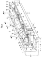
- a hinted Cylinder 2 extends a total of 3 designated device for tensioning from one the jacket of the cylinder 2 rubber or Printing blanket 10, hereinafter referred to as "printing blanket 10" called -, in the circumferential direction.
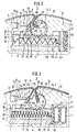
- the cylinder pit 1 has a flat bottom surface 4 and two the bottom surface 4 delimiting side surfaces 6, 7.
- the in the Device 3 arranged in the cylinder pit extends in the axis-parallel direction to the cylinder 2.
- An insert bar is scared at the first side face 6 8 with an acute parallel axis Edge 9 for receiving an angled first end 48 of the printing blanket 10.
- the fining strip 8 sits with its second end near the bottom surface 4 on one Base plate 11.
- a second insert bar 12 Extends along the second side surface 7 a second insert bar 12 with an acute angle running, axially parallel, rounded edge 13, over which a second end 49 of the printing blanket 10 drawn and one to be described in more detail Tensioning spindle 14 for tensioning the second blanket end 49 is supplied.
- the blanket 10 has at each end 48, 49 a border 51.
- the bezel 51 of the first blanket end 48 engages behind one in the insert bar 8 parallel to an axis of rotation 52 extending hooking edge 53 of a groove 54.
- Die Insert bar 8 is together with insert bar 12 executed in one piece via webs, not shown, and has cavities for receiving clamping spindle pieces 14.1 to 14.4 and racks 18 to 22.
- the Insert bar 12 is in Fig. 1 only with its end faces indicated.
- the clamping spindle 14 has a essential circular cross-section with a slot 16 for receiving the second end 49 of the to be exciting Blanket 10 on.
- the slot 16 diametrically on
- the tip circle of the toothing 17 can be the diameter correspond to the clamping spindle 14.
- the clamping spindle 14 is different in length, e.g. B. four equally long clamping spindle pieces 14.1, 14.2, 14.3, 14.4 divided, of which in Fig. 1 the clamping spindle piece 14.4 has not been shown. That also applies to another rack too, on which that is not illustrated spindle piece 14.4 with its second supports the front end.
- These spindle pieces 14.1 to 14.4 engage with the base plate 11 facing side with the toothing 17 into the top of racks 18, 19, 21, 22 a.
- the racks 18 to 22 have one square cross-section, correspond in their Length l of 0.6 times to 0.8 times the width b of Cylinder pit 1 and are with their bottom surface on the Base plate 11 of the cylinder pit 1 against each Force of a spring 23, 24, 26, 27 in the circumferential direction of the cylinder 2 movable.
- the racks 18 to 22 can also consist of a round cross-section.
- the racks 18, 19, 21, 22 are each under at the ends 29, 30, 31, 32, 33, 34 of the clamping pieces 14.1, 14.2, 14.3, 14.4 of the Clamping spindle 14 arranged so that the first end 29 of the clamping spindle piece 14.1 in the rack 18 engages the second end 30 of the clamping spindle piece 14.1 and the first end 31 of the clamping spindle piece 14.2 engages in the rack 19, the second end 32 of the clamping spindle piece and the first end 33 of the clamping spindle piece 14.3 in the rack 21, the second end 34 of the clamping spindle piece 14.3 and that not shown first end of the clamping spindle piece 14.4 engages in the rack 22.
- the racks 18, 19, 21, 22 have cohesive their top each on a pin 36, each in a round-ended in the insert bar 8 Slot 37 engages.
- All slots 37 are parallel to each other and parallel arranged to the end faces of the cylinder 2.
- the Springs 27 can also be in a first end face 38 of the rack 18, 19, 21, 22 located Blind hole 39 be held.
- the air hose 47 is closed at its first end and on its second end with a not shown Connection for the inlet and outlet of compressed air Mistake.
- the first air hose is expedient 47 assigned a second air hose 57 in parallel, which also has a nozzle, not shown is pressurized with compressed air.
- the compressed air with a pressure of 4 to 6 bar is not above one shown hose and a not shown Valve can be obtained from a compressed air system.
- the stub is located on the front side of the device 3 and is with the cylinder 2 at a standstill the said hose connected.
- the device 3 is through through holes, not shown, in the Base plate 11 fastened in the cylinder pit 1.
- screws provided with Tapped holes, not shown, of the bottom surface 4 the cylinder pit 1 interact.
- the Base plate 11 with the one-piece insert strips 8, 12 connected by means of retaining screws, not shown.
- the insert strips 8, 12 are on the clamping spindle 14 facing the circumference of the clamping spindle 14 adjusted, but so that between the insert bar 8th and the slot 16 of the clamping spindle 14 the second End 49 of the blanket 10 can be added.
- the Clamping spindle 14 can also be made in one piece.
- the first end 48 of the rubber blanket 10 is seen in a cross section, extending axially parallel in the radial direction Brought groove 54 and behind by means of the border 51 the hanging edge 53 hooked.
- the printing blanket 10 will now placed around the edge 9 of the insert bar 8.
- Rotation of the cylinder 2 enters the second end 49 the area of the edge 13 of the insert bar 12 and inserted with its border 51 in the slot 16 (Fig. 3).
- the air hoses 47, 57 are included Compressed air applied.
- the compressed air supply is used to clamp the clamping spindle 14 interrupted so that the compressed air from the Air hoses 47, 57 and springs 23, 24, 26, 27 the racks 18, 19, 21, 22 synchronously over the Clamping spindle pieces 14.1, 14.2, 14.3, 14.4 back in bring the clamping position (Fig. 2).
- the printing blanket 10 is excited.
- Cleaning or maintenance work can Clamping spindle pieces 14.1, 14.2, 14.3, 14.4 from one Gap that is in the cylinder pit 1 between the end of the device 3 and one not shown Bearer ring is removed.
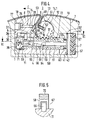
- a locking device designated overall by 56, is provided in the cylinder pit 1 parallel to the toothed racks 18, 19, 21, 22 and moves synchronously with the above-mentioned toothed rack 18, 19, 21, 22 transversely to the axis of rotation 52 of the clamping spindle 14.
- the locking device 56 consists of a toothed rack 58 with a bore 59 for receiving a bolt 61, which is connected at its first end in a non-positive and positive manner to a support plate 62, which in turn is spaced apart from the second end face 41 of the toothed rack 58 by means of compression springs 63.
- the bolt 61 has a z. B. wedge or truncated cone 64.
- the opening 59 is followed by an opening for receiving a two-armed lever 66 which is mounted on the rack fixed by means of a retaining bolt 67.
- the pawl 69 is pressed into the toothing 71 with the force of a spring, not shown.
- the method of operation is as follows: In the tensioned position according to FIG.
- the blanket 10 cannot loosen when the cylinder 2 rotates in the counterclockwise direction C as a result of a flexing movement, since the lever 66 engages with the pawl 69 in the toothing 71 of the base plate 11.
- the printing blanket 10 can, however, continue to tension itself if the compression springs 23, 24, 26, 27 expand further.
- the toothed rack 58 with its toothing 72 moves in the direction of the air hoses 47, 57 and the second end 69 of the lever 66 engages one tooth further to the right. If the tensioning device is now to be relaxed for the purpose of changing the printing blanket, compressed air is introduced into the air hoses 47, 57.
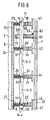
- the insert bar 8 shows an ejection element designated as a whole by 73 arranged, which consists of a in the insert 8th parallel to the direction of movement of the racks 18, 19, 21, 22 movably guided pin 74, which with its first end 76 with an unspecified one Piston of a piston-cylinder unit 77 force and is positively connected.
- the pin 74 presses in If the piston-cylinder unit 77 is actuated, e.g. B.
- the sliding pins 74 can also be driven by means of an axis of rotation 52 of the clamping spindle 14 Camshaft arranged in parallel in the insert strip 8 respectively.
Landscapes
- Supply, Installation And Extraction Of Printed Sheets Or Plates (AREA)
Applications Claiming Priority (3)
| Application Number | Priority Date | Filing Date | Title |
|---|---|---|---|
| DE4326250A DE4326250C2 (de) | 1993-08-05 | 1993-08-05 | Spannvorrichtung in einer Rotationsdruckmaschine |
| DE4326250 | 1993-08-05 | ||
| EP94111840A EP0638420B1 (fr) | 1993-08-05 | 1994-07-29 | Dispositif pour tendre dans une machine à imprimer rotative |
Related Parent Applications (1)
| Application Number | Title | Priority Date | Filing Date |
|---|---|---|---|
| EP94111840A Division EP0638420B1 (fr) | 1993-08-05 | 1994-07-29 | Dispositif pour tendre dans une machine à imprimer rotative |
Publications (3)
| Publication Number | Publication Date |
|---|---|
| EP0844082A2 true EP0844082A2 (fr) | 1998-05-27 |
| EP0844082A3 EP0844082A3 (fr) | 1998-07-08 |
| EP0844082B1 EP0844082B1 (fr) | 2001-04-04 |
Family
ID=6494486
Family Applications (2)
| Application Number | Title | Priority Date | Filing Date |
|---|---|---|---|
| EP94111840A Expired - Lifetime EP0638420B1 (fr) | 1993-08-05 | 1994-07-29 | Dispositif pour tendre dans une machine à imprimer rotative |
| EP98102334A Expired - Lifetime EP0844082B1 (fr) | 1993-08-05 | 1994-07-29 | Dispositif de serrage pour une machine à imprimer rotative |
Family Applications Before (1)
| Application Number | Title | Priority Date | Filing Date |
|---|---|---|---|
| EP94111840A Expired - Lifetime EP0638420B1 (fr) | 1993-08-05 | 1994-07-29 | Dispositif pour tendre dans une machine à imprimer rotative |
Country Status (4)
| Country | Link |
|---|---|
| US (1) | US5503072A (fr) |
| EP (2) | EP0638420B1 (fr) |
| JP (1) | JP2746839B2 (fr) |
| DE (3) | DE4326250C2 (fr) |
Cited By (1)
| Publication number | Priority date | Publication date | Assignee | Title |
|---|---|---|---|---|
| EP1172207A1 (fr) * | 2000-07-12 | 2002-01-16 | Kabushiki Kaisha Tokyo Kikai Seisakusho | Cylindre de blanchet permettant de faciliter le montage et le démontage d'un blanchet |
Families Citing this family (17)
| Publication number | Priority date | Publication date | Assignee | Title |
|---|---|---|---|---|
| FR2727350B1 (fr) * | 1994-11-24 | 1997-02-14 | Heidelberg Harris Sa | Dispositif de fixation d'une forme d'impression souple |
| DE19602104C2 (de) * | 1996-01-22 | 2000-09-14 | Heidelberger Druckmasch Ag | Klemm- und Ziehvorrichtung für Aufzüge von Zylindern in Druckmaschinen |
| US6073558A (en) * | 1998-07-20 | 2000-06-13 | Heidelberger Druckmaschinen Ag | Printing press having blanket cylinder with filler bar and blanket |
| US6026746A (en) * | 1998-09-22 | 2000-02-22 | E. R. Smith Associates, Inc. | Lock-up assembly for plate cylinders of rotary presses |
| DE19922021A1 (de) * | 1999-05-12 | 2000-11-23 | Zirkon Druckmaschinen Gmbh | Einrichtung zum Befestigen und Spannen von Druckplatten und Gummitücher |
| DE19924786B4 (de) * | 1999-05-29 | 2004-11-04 | Koenig & Bauer Ag | Vorrichtung zum Befestigen einer biegsamen Platte auf einem Zylinder einer Rotationsdruckmaschine |
| DE10015165B4 (de) * | 2000-03-27 | 2004-01-29 | Koenig & Bauer Ag | Vorrichtung zur Zuführung von Druckmittel |
| DE10250684B3 (de) * | 2002-10-31 | 2004-04-01 | Koenig & Bauer Ag | Verfahren zur Herstellung eines Rotationskörpers und Rotationskörper einer Druckmaschine |
| DE102006052412B4 (de) * | 2006-10-23 | 2015-01-15 | Heidelberger Druckmaschinen Ag | Trommel zum Fördern eines Bogens |
| JP5108448B2 (ja) | 2006-10-23 | 2012-12-26 | ハイデルベルガー ドルツクマシーネン アクチエンゲゼルシヤフト | シートをフィードするための胴 |
| DE102007047892B4 (de) * | 2007-11-29 | 2010-07-15 | Koenig & Bauer Aktiengesellschaft | Zylinder einer Druckmaschine mit mindestens einem unter dessen Mantelfläche in dessen Axialrichtung verlaufenden Kanal |
| KR101779160B1 (ko) * | 2011-01-13 | 2017-09-27 | 미래나노텍(주) | 롤유닛 및 이를 이용한 패턴 형성 장치 |
| DE102012207109B3 (de) * | 2012-04-27 | 2013-05-02 | Koenig & Bauer Aktiengesellschaft | Verfahren zum Anordnen einer Druckform auf einen Plattenzylinder |
| JP6297479B2 (ja) * | 2014-12-05 | 2018-03-20 | 株式会社ミヤコシ | 刷版の固定装置 |
| US10737481B2 (en) * | 2017-07-03 | 2020-08-11 | Manroland Goss Web Systems Gmbh | Plate cylinder with plate lockup mechanism and related printing press and method |
| DE102020123196A1 (de) * | 2020-09-04 | 2022-03-10 | Kolbus Gmbh & Co. Kg | Vorrichtung zum Spannen eines bogenförmigen Walzenbezugs um eine Walze |
| CN114030289B (zh) * | 2021-11-05 | 2023-04-18 | 江苏富台机械科技有限公司 | 一种水性印刷机多用挂版机构 |
Family Cites Families (15)
| Publication number | Priority date | Publication date | Assignee | Title |
|---|---|---|---|---|
| GB349921A (en) * | 1929-11-01 | 1931-06-01 | Addressograph Co | Improvements in or relating to printing machines |
| US2953090A (en) * | 1958-03-31 | 1960-09-20 | Wood Newspaper Mach Corp | Tension lock-up device |
| US3715981A (en) * | 1970-06-29 | 1973-02-13 | Hamilton Tool Co | Fluid actuator and lock for printing plate cylinders |
| JPS5780057A (en) * | 1980-11-05 | 1982-05-19 | Toshiba Mach Co Ltd | Mounting mechanism for blanket in rotary printing press |
| DE8101707U1 (de) * | 1981-01-24 | 1981-06-04 | M.A.N.- Roland Druckmaschinen AG, 6050 Offenbach | Vorrichtung zum spannen eines gummituches oder einer platte auf einen zylinder einer offsetdruckmaschine |
| JPS57132720A (en) * | 1981-02-10 | 1982-08-17 | Tokyo Shibaura Electric Co | Cable processor for self-running vehicle |
| JPS5938043U (ja) * | 1982-09-01 | 1984-03-10 | 株式会社新幸機械製作所 | 版胴への版フイルム巻込装置 |
| US4577560A (en) * | 1984-08-20 | 1986-03-25 | R. R. Donnelley & Sons Company | Gapless lock-up for offset printing cylinders |
| DE3443353A1 (de) * | 1984-11-28 | 1986-06-05 | M.A.N.- Roland Druckmaschinen AG, 6050 Offenbach | Vorrichtung zum spannen von druckplatten auf flexo- und offset-plattenzylindern |
| GB8616952D0 (en) * | 1986-07-11 | 1986-08-20 | Hercules Inc | Printing plate |
| DE3702032A1 (de) * | 1987-01-24 | 1988-08-04 | Basf Ag | Vorrichtung zum spannen von druckplatten |
| DE3731039A1 (de) * | 1987-09-16 | 1989-03-30 | Koenig & Bauer Ag | Einrichtung zum klemmen biegsamer druckplatten auf dem plattenzylinder einer rotationsdruckmaschine |
| JPH0437340U (fr) * | 1990-07-20 | 1992-03-30 | ||
| DE4127714A1 (de) * | 1991-08-22 | 1993-02-25 | Koenig & Bauer Ag | Einrichtung zum befestigen und spannen eines drucktuches auf einem zylinder einer druckmaschine |
| JP2905652B2 (ja) * | 1992-10-29 | 1999-06-14 | 株式会社桜井グラフィックシステムズ | 印刷機の版くわえ装置 |
-
1993
- 1993-08-05 DE DE4326250A patent/DE4326250C2/de not_active Expired - Fee Related
-
1994
- 1994-07-29 EP EP94111840A patent/EP0638420B1/fr not_active Expired - Lifetime
- 1994-07-29 EP EP98102334A patent/EP0844082B1/fr not_active Expired - Lifetime
- 1994-07-29 DE DE59407724T patent/DE59407724D1/de not_active Expired - Fee Related
- 1994-07-29 DE DE59409719T patent/DE59409719D1/de not_active Expired - Fee Related
- 1994-08-03 US US08/285,210 patent/US5503072A/en not_active Expired - Fee Related
- 1994-08-04 JP JP6183542A patent/JP2746839B2/ja not_active Expired - Fee Related
Cited By (2)
| Publication number | Priority date | Publication date | Assignee | Title |
|---|---|---|---|---|
| EP1172207A1 (fr) * | 2000-07-12 | 2002-01-16 | Kabushiki Kaisha Tokyo Kikai Seisakusho | Cylindre de blanchet permettant de faciliter le montage et le démontage d'un blanchet |
| US6457411B2 (en) | 2000-07-12 | 2002-10-01 | Kabushiki Kaisha Tokyo Kikai Seisakusho | Blanket cylinder providing for ready mounting and dismounting of a blanket |
Also Published As
| Publication number | Publication date |
|---|---|
| EP0638420B1 (fr) | 1999-01-27 |
| JPH0760949A (ja) | 1995-03-07 |
| EP0844082B1 (fr) | 2001-04-04 |
| DE59407724D1 (de) | 1999-03-11 |
| EP0638420A1 (fr) | 1995-02-15 |
| EP0844082A3 (fr) | 1998-07-08 |
| DE4326250A1 (de) | 1995-02-09 |
| DE4326250C2 (de) | 1996-05-15 |
| JP2746839B2 (ja) | 1998-05-06 |
| DE59409719D1 (de) | 2001-05-10 |
| US5503072A (en) | 1996-04-02 |
Similar Documents
| Publication | Publication Date | Title |
|---|---|---|
| EP0844082B1 (fr) | Dispositif de serrage pour une machine à imprimer rotative | |
| EP0270816B1 (fr) | Tête d'extrusion | |
| DE2032357A1 (de) | Siebdruckmaschine | |
| EP0638421B1 (fr) | Cylindre à blanchet ou cylindre d'impression | |
| DE4326248C2 (de) | Spannvorrichtung in einer Rotationsdruckmaschine | |
| DE19953664A1 (de) | Vorrichtung zur Sicherung eines korrekten Zahneingriffes beim Einkoppeln zweier Zahnräder | |
| DE9317726U1 (de) | Spindel | |
| DE19906726B4 (de) | Reinigungsvorrichtung in einer Druckmaschine | |
| DE3315488A1 (de) | Vorrichtung zum spannen von druckplatten | |
| EP0737574B1 (fr) | Dispositif pour tendre dans une machine à imprimer rotative | |
| DE3933678C2 (fr) | ||
| DE2554716A1 (de) | Offenend-spinnaggregat mit einer aufloesewalze | |
| DE3834429C1 (en) | Gearwheel for driving the cylinders of offset printing machines | |
| DE9320590U1 (de) | Spannvorrichtung in einer Rotationsdruckmaschine | |
| DE3336919C2 (de) | Vorrichtung zum zonenweisen Verstellen eines Farbmessers | |
| DE9320591U1 (de) | Gummi-/Drucktuchzylinder | |
| EP0567797A1 (fr) | Dispositif pour mettre en biais des plaques d'impression sur le cylindre porte-plaque de machines à imprimer, en particulier des machines pour l'impression offset de feuilles | |
| DE4442300A1 (de) | Betätigungseinrichtung für eine Spannvorrichtung für Druckplatten in Rotationsdruckmaschinen | |
| DE3319246A1 (de) | Schnellspannleiste fuer druckplatten | |
| DE1761642C (de) | Vorrichtung zum Befestigen von Druck platten auf dem Plattenzylmder einer Rota tionsdruckmaschine | |
| DE19948954A1 (de) | Plattenzylinder einer Druckmaschine mit Plattenspannvorrichtung | |
| DE2425011C3 (de) | Anstellvorrichtung für ein Mehrwalzendruckwerk, insbesondere Flexodruckwerk | |
| DE2754080B2 (de) | Vorrichtung zum registerhaltigen Spannen von Druckplatten auf dem Plattenzylinder von Druckmaschinen | |
| DE19627034A1 (de) | Einrichtung zum Betrieb eines Klischee-Zylinders sowie Klischee-Träger | |
| DE2425011B2 (de) | Anstellvorrichtung fuer ein mehrwalzendruckwerk, insbesondere flexodruckwerk |
Legal Events
| Date | Code | Title | Description |
|---|---|---|---|
| PUAI | Public reference made under article 153(3) epc to a published international application that has entered the european phase |
Free format text: ORIGINAL CODE: 0009012 |
|
| PUAL | Search report despatched |
Free format text: ORIGINAL CODE: 0009013 |
|
| AC | Divisional application: reference to earlier application |
Ref document number: 638420 Country of ref document: EP |
|
| AK | Designated contracting states |
Kind code of ref document: A2 Designated state(s): CH DE FR GB IT LI SE |
|
| AK | Designated contracting states |
Kind code of ref document: A3 Designated state(s): CH DE FR GB IT LI SE |
|
| RAP1 | Party data changed (applicant data changed or rights of an application transferred) |
Owner name: KOENIG & BAUER AKTIENGESELLSCHAFT |
|
| 17P | Request for examination filed |
Effective date: 19981228 |
|
| GRAG | Despatch of communication of intention to grant |
Free format text: ORIGINAL CODE: EPIDOS AGRA |
|
| GRAG | Despatch of communication of intention to grant |
Free format text: ORIGINAL CODE: EPIDOS AGRA |
|
| GRAH | Despatch of communication of intention to grant a patent |
Free format text: ORIGINAL CODE: EPIDOS IGRA |
|
| 17Q | First examination report despatched |
Effective date: 20000804 |
|
| GRAH | Despatch of communication of intention to grant a patent |
Free format text: ORIGINAL CODE: EPIDOS IGRA |
|
| GRAA | (expected) grant |
Free format text: ORIGINAL CODE: 0009210 |
|
| ITF | It: translation for a ep patent filed | ||
| AC | Divisional application: reference to earlier application |
Ref document number: 638420 Country of ref document: EP |
|
| AK | Designated contracting states |
Kind code of ref document: B1 Designated state(s): CH DE FR GB IT LI SE |
|
| REG | Reference to a national code |
Ref country code: CH Ref legal event code: EP |
|
| GBT | Gb: translation of ep patent filed (gb section 77(6)(a)/1977) |
Effective date: 20010404 |
|
| REF | Corresponds to: |
Ref document number: 59409719 Country of ref document: DE Date of ref document: 20010510 |
|
| ET | Fr: translation filed | ||
| REG | Reference to a national code |
Ref country code: GB Ref legal event code: IF02 |
|
| PLBE | No opposition filed within time limit |
Free format text: ORIGINAL CODE: 0009261 |
|
| STAA | Information on the status of an ep patent application or granted ep patent |
Free format text: STATUS: NO OPPOSITION FILED WITHIN TIME LIMIT |
|
| 26N | No opposition filed | ||
| PGFP | Annual fee paid to national office [announced via postgrant information from national office to epo] |
Ref country code: GB Payment date: 20030625 Year of fee payment: 10 |
|
| PGFP | Annual fee paid to national office [announced via postgrant information from national office to epo] |
Ref country code: SE Payment date: 20030716 Year of fee payment: 10 |
|
| PGFP | Annual fee paid to national office [announced via postgrant information from national office to epo] |
Ref country code: FR Payment date: 20030723 Year of fee payment: 10 |
|
| PGFP | Annual fee paid to national office [announced via postgrant information from national office to epo] |
Ref country code: CH Payment date: 20030731 Year of fee payment: 10 |
|
| PG25 | Lapsed in a contracting state [announced via postgrant information from national office to epo] |
Ref country code: GB Free format text: LAPSE BECAUSE OF NON-PAYMENT OF DUE FEES Effective date: 20040729 |
|
| PG25 | Lapsed in a contracting state [announced via postgrant information from national office to epo] |
Ref country code: SE Free format text: LAPSE BECAUSE OF NON-PAYMENT OF DUE FEES Effective date: 20040730 |
|
| PG25 | Lapsed in a contracting state [announced via postgrant information from national office to epo] |
Ref country code: LI Free format text: LAPSE BECAUSE OF NON-PAYMENT OF DUE FEES Effective date: 20040731 Ref country code: CH Free format text: LAPSE BECAUSE OF NON-PAYMENT OF DUE FEES Effective date: 20040731 |
|
| PGFP | Annual fee paid to national office [announced via postgrant information from national office to epo] |
Ref country code: DE Payment date: 20040927 Year of fee payment: 11 |
|
| EUG | Se: european patent has lapsed | ||
| REG | Reference to a national code |
Ref country code: CH Ref legal event code: PL |
|
| GBPC | Gb: european patent ceased through non-payment of renewal fee |
Effective date: 20040729 |
|
| PG25 | Lapsed in a contracting state [announced via postgrant information from national office to epo] |
Ref country code: FR Free format text: LAPSE BECAUSE OF NON-PAYMENT OF DUE FEES Effective date: 20050331 |
|
| REG | Reference to a national code |
Ref country code: FR Ref legal event code: ST |
|
| PG25 | Lapsed in a contracting state [announced via postgrant information from national office to epo] |
Ref country code: IT Free format text: LAPSE BECAUSE OF NON-PAYMENT OF DUE FEES;WARNING: LAPSES OF ITALIAN PATENTS WITH EFFECTIVE DATE BEFORE 2007 MAY HAVE OCCURRED AT ANY TIME BEFORE 2007. THE CORRECT EFFECTIVE DATE MAY BE DIFFERENT FROM THE ONE RECORDED. Effective date: 20050729 |
|
| PG25 | Lapsed in a contracting state [announced via postgrant information from national office to epo] |
Ref country code: DE Free format text: LAPSE BECAUSE OF NON-PAYMENT OF DUE FEES Effective date: 20060201 |