EP0844085A1 - Dispositif de lavage pour nettoyer un cylindre d'une machine d'impression - Google Patents
Dispositif de lavage pour nettoyer un cylindre d'une machine d'impression Download PDFInfo
- Publication number
- EP0844085A1 EP0844085A1 EP97120045A EP97120045A EP0844085A1 EP 0844085 A1 EP0844085 A1 EP 0844085A1 EP 97120045 A EP97120045 A EP 97120045A EP 97120045 A EP97120045 A EP 97120045A EP 0844085 A1 EP0844085 A1 EP 0844085A1
- Authority
- EP
- European Patent Office
- Prior art keywords
- cleaning fluid
- housing
- line
- coupled
- washing
- Prior art date
- Legal status (The legal status is an assumption and is not a legal conclusion. Google has not performed a legal analysis and makes no representation as to the accuracy of the status listed.)
- Granted
Links
- 238000004140 cleaning Methods 0.000 title claims abstract description 58
- 238000005406 washing Methods 0.000 title claims description 50
- 238000007639 printing Methods 0.000 title claims description 6
- 239000012530 fluid Substances 0.000 claims abstract description 45
- 238000004062 sedimentation Methods 0.000 claims abstract description 24
- XLYOFNOQVPJJNP-UHFFFAOYSA-N water Substances O XLYOFNOQVPJJNP-UHFFFAOYSA-N 0.000 claims abstract description 24
- 239000003599 detergent Substances 0.000 claims description 15
- 230000005484 gravity Effects 0.000 claims description 6
- 239000007788 liquid Substances 0.000 description 9
- 238000011010 flushing procedure Methods 0.000 description 7
- 239000007921 spray Substances 0.000 description 7
- 239000007787 solid Substances 0.000 description 5
- 238000009825 accumulation Methods 0.000 description 4
- 239000002904 solvent Substances 0.000 description 4
- 239000000356 contaminant Substances 0.000 description 3
- 238000007645 offset printing Methods 0.000 description 3
- 239000003973 paint Substances 0.000 description 3
- 238000000926 separation method Methods 0.000 description 3
- 239000000428 dust Substances 0.000 description 2
- 239000000843 powder Substances 0.000 description 2
- 239000010802 sludge Substances 0.000 description 2
- 235000013311 vegetables Nutrition 0.000 description 2
- -1 color residues Substances 0.000 description 1
- 238000011109 contamination Methods 0.000 description 1
- 238000004821 distillation Methods 0.000 description 1
- 230000000694 effects Effects 0.000 description 1
- KEUKAQNPUBYCIC-UHFFFAOYSA-N ethaneperoxoic acid;hydrogen peroxide Chemical compound OO.CC(=O)OO KEUKAQNPUBYCIC-UHFFFAOYSA-N 0.000 description 1
- 239000004744 fabric Substances 0.000 description 1
- 239000012535 impurity Substances 0.000 description 1
- 238000000034 method Methods 0.000 description 1
- 239000000203 mixture Substances 0.000 description 1
- 238000012545 processing Methods 0.000 description 1
- 230000001172 regenerating effect Effects 0.000 description 1
- 238000012958 reprocessing Methods 0.000 description 1
- 238000005507 spraying Methods 0.000 description 1
- 238000009736 wetting Methods 0.000 description 1
Images


Classifications
-
- B—PERFORMING OPERATIONS; TRANSPORTING
- B41—PRINTING; LINING MACHINES; TYPEWRITERS; STAMPS
- B41F—PRINTING MACHINES OR PRESSES
- B41F35/00—Cleaning arrangements or devices
-
- B—PERFORMING OPERATIONS; TRANSPORTING
- B41—PRINTING; LINING MACHINES; TYPEWRITERS; STAMPS
- B41P—INDEXING SCHEME RELATING TO PRINTING, LINING MACHINES, TYPEWRITERS, AND TO STAMPS
- B41P2235/00—Cleaning
- B41P2235/30—Recovering used solvents or residues
Definitions
- the invention relates to a washing device according to the preamble of the main claim.
- a device of this kind is in German patent application P 196 14 395.0-27 the applicant of April 12, 1996.
- the device serves under another of cleaning a cylinder in a printing press, the device with a circuit for the supply and discharge of cleaning fluid (Detergent / solvent and / or water) with the interposition of a treatment plant is coupled.
- the cleaning device are used as a treatment plant at least two for the used (contaminated) cleaning fluid Sedimentation devices arranged in series. These separate using gravity suspended the cleaning fluid into the three components Solids, detergents / solvents and water.
- EP 0 531 773 B1 is a device for washing a printing press cylinder known as a treatment plant a distillation unit and a downstream gravity separator, which the distillate in water and separates solvent. After separation, water and solvent individually and successively fed back to the washing device.
- DE 31 20 983 A1 describes a device for washing the blanket cylinder an offset printing machine known.
- the device has one Washing roller, here referred to as a brush roller, cleaning a blanket cylinder serves in an offset printing machine.
- the cleaning device has, among other things, a special design of the housing. This is said to be an undesirable Spraying washing liquid on other parts of the printing machine be prevented. Furthermore, the bottom of the housing is used as a tub Collect used washing liquid and trained from contamination. The washing liquid is not prepared.
- a spray nozzle which has a cleaning liquid jet, intermittent, among other things, along the bottom of the case Pan causes soiling as well as the washing liquid in the direction flushed to a drain and thus the accumulation of contaminants, which can prevent it from settling out as mud and liquid.
- the washing liquid is also the use of water for the cleaning fluid jet possible.
- the object of the invention is to develop a solution by which the accumulation of contaminated cleaning fluid at the bottom of the housing Washing device is avoidable.
- the advantage of this design is that flushing with pre-cleaned cleaning fluid prevents the accumulation and possibly the accumulation of contaminated cleaning fluid in the housing. Clogging of the drain opening is also prevented. Is preferred during the operating position Washing "the housing base of the washing device is continuously flushed out by the pre-cleaned detergent. Alternatively, the flushing can also be operated intermittently. It is also advantageous if the flushing of the cylinder jacket surface is maintained for a short time afterwards. This ensures that contaminated cleaning fluid flows away better through the use of used, but pre-cleaned cleaning fluid, additional consumption of cleaning fluid is not required in terms of quantity, since detergent already in circulation can be used for the flushing.
- a washing device 1 is assigned in a printing unit of an offset printing press to a cylinder 21, here the blanket cylinder, adjacent.
- the washing device 1 has a housing 2 which has an approximately rectangular cross section and extends beyond the full width of the cylinder 21.
- the housing 2 accommodates a rotatable, separately drivable washing roller 11, for example a washing brush equipped with brushes.
- Spray nozzles 18 arranged in a row on the housing 2 are directed onto the washing roller 11 and are coupled to a water supply.
- a doctor blade 19 which interacts with the washing roller 11, and also a cleaning fluid supply which is likewise directed onto the washing roller 11 and which, by means of a row of spray nozzles 20, wet the washing roller 11 with a vegetable detergent.
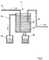
- a nozzle 4 is arranged on an end face 3 of the housing 2 and is coupled to a feed line 9 for the pre-cleaned cleaning fluid (detergent).
- the sedimentation device 7 represents a receptacle for the contaminated cleaning fluid, which, in addition to the cleaning fluid (detergent) and water used, is also contaminated with contaminants such as color residues, paper dust, powder, sludge, and possibly paint residues.
- the return line 6 coming from the washing device 1 opens in the vicinity of the bottom of the sedimentation device 7.
- the feed line 9, which is coupled to the washing device 1, begins in the central region of the sedimentation device 7.
- An overflow line 14 is arranged in the upper area of the sedimentation device 7 and is coupled to a receiving container 15 for cleaned detergent.
- a supply line (not shown) leads from the receptacle 15, possibly with the interposition of a filter or other treatment system (further sedimentation device), to the spray nozzles 20 of the washing device 1.
- the feed line 9 leads pre-cleaned cleaning fluid 12 with the interposition of a filter device 8 and pump to a nozzle 4 which is arranged in the region of the end faces 3 of the washing device 1.
- the bypass line 10 is used to set the pressure for flushing in the feed line 9 and the filter 8 is operated as a crossflow filter (self-cleaning).
- the pre-cleaned cleaning fluid 12 can be acted upon by the nozzle 4 and generates a flow 17 in the direction of the outlet opening 5 at the bottom of the housing 2 of the washing device 1.
- a plurality of nozzles 4 coupled to the feed line 9 can be arranged across the width of the housing 2 to generate a common flow 17 in the direction of the discharge opening 5.
- the drain opening 5 in connection with the return line 6 is preferably connected to an intermediate suction device.
- a nozzle 4 is arranged in the region of each end face 3, the drain opening 5 is arranged centrally in the housing base. Every nozzle 4 has a separate feed line 9, which is coupled to the sedimentation system 7 is.
- the housing 2 of the washing device 1 has an advantageous design a slope leading to the next drain opening 5.
- the spray nozzles 18, 20 wet the washing roller 11 with water and / or cleaning fluid (detergent).
- the washing roller 11 is placed against the cylinder 10 and removes the adhering impurities.
- the contaminated cleaning fluid collects at the bottom of the housing 2 and over which the gradient flows in the floor, supported by the flow 17 generated by the nozzle 4, via the outlet opening 5 with the return line 6, the contaminated cleaning fluid into the sedimentation device 7.
- the drainage can take place by suction of the contaminated cleaning fluid are supported.
- the contaminated cleaning fluid separates into at least two components (phases) under the influence of gravity.
- the first phase consists of dirty water 13 (suspended solids and water) and settles on the bottom of the sedimentation device.
- the second phase consists of pre-cleaned cleaning fluid 12 (detergent).
- the pre-cleaned cleaning fluid 12 is supplied to the nozzle 4 under pressure by means of the supply line 9.
- the nozzle 4 generates a flow 17 at the bottom of the housing 2 with the pre-cleaned cleaning fluid and flushes the bottom and the drain opening 5 along the housing 2. Flushing with pre-cleaned cleaning fluid is preferably combined with suctioning off the contaminated cleaning fluid via the drain opening 5.
- the supply of pre-cleaned cleaning fluid 12 preferably begins shortly before the actual cleaning operation and is maintained for a short time, for example 60 seconds, after the cleaning operation has ended. This prevents contaminated cleaning fluid from accumulating and possibly adhering to the housing base, and the cleaning effect when flushing is increased.
Landscapes
- Inking, Control Or Cleaning Of Printing Machines (AREA)
Applications Claiming Priority (2)
| Application Number | Priority Date | Filing Date | Title |
|---|---|---|---|
| DE19648193A DE19648193C2 (de) | 1996-11-21 | 1996-11-21 | Waschvorrichtung zum Reinigen eines Zylinders einer Druckmaschine |
| DE19648193 | 1996-11-21 |
Publications (2)
| Publication Number | Publication Date |
|---|---|
| EP0844085A1 true EP0844085A1 (fr) | 1998-05-27 |
| EP0844085B1 EP0844085B1 (fr) | 2001-08-01 |
Family
ID=7812342
Family Applications (1)
| Application Number | Title | Priority Date | Filing Date |
|---|---|---|---|
| EP97120045A Expired - Lifetime EP0844085B1 (fr) | 1996-11-21 | 1997-11-15 | Dispositif de lavage pour nettoyer un cylindre d'une machine d'impression |
Country Status (4)
| Country | Link |
|---|---|
| EP (1) | EP0844085B1 (fr) |
| JP (1) | JP3017149B2 (fr) |
| AT (1) | ATE203710T1 (fr) |
| DE (2) | DE19648193C2 (fr) |
Cited By (4)
| Publication number | Priority date | Publication date | Assignee | Title |
|---|---|---|---|---|
| DE10163363A1 (de) * | 2001-12-21 | 2003-07-17 | Ludwig E Betz Gmbh Druckmaschi | Vorrichtungen und Verfahren zum Reinigen von Farbwerken |
| EP1486330A3 (fr) * | 2003-06-12 | 2006-05-24 | Baldwin-Japan Ltd. | Dispositif de nettoyage d'un cylindre |
| EP1864810A3 (fr) * | 2006-06-09 | 2009-04-08 | Technotrans AG | Dispositif de nettoyage pour surfaces de cylindre d'impression |
| WO2023078865A1 (fr) * | 2021-11-03 | 2023-05-11 | Bobst Bielefeld Gmbh | Système de récupération d'une solution de nettoyage et machine d'impression |
Families Citing this family (4)
| Publication number | Priority date | Publication date | Assignee | Title |
|---|---|---|---|---|
| DE10202990A1 (de) * | 2002-01-26 | 2003-07-31 | Roland Man Druckmasch | Waschvorrichtung für Zylinder von Rotationsdruckmaschinen und Verfahren |
| DE10313014A1 (de) * | 2003-03-24 | 2004-10-07 | Baldwin Germany Gmbh | Druckmaschinen-Spül- und -entleervorrichtung und Verfahren |
| JP2006326849A (ja) * | 2005-05-23 | 2006-12-07 | Komori Corp | 印刷機の洗浄装置 |
| JP2016022586A (ja) * | 2014-07-16 | 2016-02-08 | 株式会社小森コーポレーション | 凹版印刷機のワイピング装置 |
Citations (3)
| Publication number | Priority date | Publication date | Assignee | Title |
|---|---|---|---|---|
| EP0350405A2 (fr) * | 1988-07-07 | 1990-01-10 | Jean Lucien Sarda | Centrale de nettoyage et traitement pour l'entretien des presses à imprimer |
| US5183572A (en) * | 1991-08-23 | 1993-02-02 | Curtis Manufacturing Company, Inc. | Cross-flow filtration system and method for filtering a solvent-particulate waste stream |
| EP0531773A1 (fr) * | 1991-09-03 | 1993-03-17 | MAN Roland Druckmaschinen AG | Dispositif pour le nettoyage d'un cylindre d'une machine à imprimer |
Family Cites Families (3)
| Publication number | Priority date | Publication date | Assignee | Title |
|---|---|---|---|---|
| GB1169668A (en) * | 1967-04-20 | 1969-11-05 | Akerlund & Rausing Ab | Improvements in and relating to Means for Washing a Cylinder in a Printing Press |
| DE3120983A1 (de) * | 1980-05-28 | 1982-04-29 | Dai Nippon Insatsu K.K., Tokyo | Vorrichtung zum waschen des gummituchzylinders einer rotations-offsetpresse |
| DE19614395C2 (de) * | 1996-04-12 | 1999-08-12 | Roland Man Druckmasch | Verfahren und Vorrichtung zum Reinigen eines Druckmaschinenzylinders und/oder von Walzen |
-
1996
- 1996-11-21 DE DE19648193A patent/DE19648193C2/de not_active Expired - Fee Related
-
1997
- 1997-11-15 AT AT97120045T patent/ATE203710T1/de not_active IP Right Cessation
- 1997-11-15 DE DE59704184T patent/DE59704184D1/de not_active Expired - Lifetime
- 1997-11-15 EP EP97120045A patent/EP0844085B1/fr not_active Expired - Lifetime
- 1997-11-18 JP JP9316887A patent/JP3017149B2/ja not_active Expired - Fee Related
Patent Citations (3)
| Publication number | Priority date | Publication date | Assignee | Title |
|---|---|---|---|---|
| EP0350405A2 (fr) * | 1988-07-07 | 1990-01-10 | Jean Lucien Sarda | Centrale de nettoyage et traitement pour l'entretien des presses à imprimer |
| US5183572A (en) * | 1991-08-23 | 1993-02-02 | Curtis Manufacturing Company, Inc. | Cross-flow filtration system and method for filtering a solvent-particulate waste stream |
| EP0531773A1 (fr) * | 1991-09-03 | 1993-03-17 | MAN Roland Druckmaschinen AG | Dispositif pour le nettoyage d'un cylindre d'une machine à imprimer |
Cited By (8)
| Publication number | Priority date | Publication date | Assignee | Title |
|---|---|---|---|---|
| DE10163363A1 (de) * | 2001-12-21 | 2003-07-17 | Ludwig E Betz Gmbh Druckmaschi | Vorrichtungen und Verfahren zum Reinigen von Farbwerken |
| DE10163363B4 (de) * | 2001-12-21 | 2005-06-09 | Ludwig E. Betz Gmbh Druckmaschinentechnik | Vorrichtung und Verfahren zum Reinigen von Farbwerken |
| EP1486330A3 (fr) * | 2003-06-12 | 2006-05-24 | Baldwin-Japan Ltd. | Dispositif de nettoyage d'un cylindre |
| US7219605B2 (en) | 2003-06-12 | 2007-05-22 | Baldwin-Japan, Ltd. | Cylinder cleaning apparatus |
| EP1864810A3 (fr) * | 2006-06-09 | 2009-04-08 | Technotrans AG | Dispositif de nettoyage pour surfaces de cylindre d'impression |
| WO2023078865A1 (fr) * | 2021-11-03 | 2023-05-11 | Bobst Bielefeld Gmbh | Système de récupération d'une solution de nettoyage et machine d'impression |
| US20250001755A1 (en) * | 2021-11-03 | 2025-01-02 | Bobst Bielefeld Gmbh | System for recovering a cleaning solution and printing machine |
| US12594756B2 (en) * | 2021-11-03 | 2026-04-07 | Bobst Bielefeld Gmbh | System for recovering a cleaning solution and printing machine |
Also Published As
| Publication number | Publication date |
|---|---|
| JP3017149B2 (ja) | 2000-03-06 |
| DE19648193C2 (de) | 1999-04-01 |
| ATE203710T1 (de) | 2001-08-15 |
| JPH10157082A (ja) | 1998-06-16 |
| DE19648193A1 (de) | 1998-06-04 |
| DE59704184D1 (de) | 2001-09-06 |
| EP0844085B1 (fr) | 2001-08-01 |
Similar Documents
| Publication | Publication Date | Title |
|---|---|---|
| DE69718007T2 (de) | Vorrichtung und verfahren zum reinigen von flexographischen druckplatten | |
| EP0844085B1 (fr) | Dispositif de lavage pour nettoyer un cylindre d'une machine d'impression | |
| DE4238201A1 (fr) | ||
| DE10065373B4 (de) | Reinigungsvorrichtung mit einem Flüssigkeitsbehälter und einer Entfeuchtungseinrichtung | |
| EP0514670B1 (fr) | Dispositif pour le nettoyage d'un cylindre d'une machine d'impression | |
| DE4424581C1 (de) | Vorrichtung zum Entfernen von Farbe aus einem Farbwerk | |
| DE19614395C2 (de) | Verfahren und Vorrichtung zum Reinigen eines Druckmaschinenzylinders und/oder von Walzen | |
| DE19520550A1 (de) | Reinigungsvorrichtung für Druckmaschinenzylinder | |
| EP0531773A1 (fr) | Dispositif pour le nettoyage d'un cylindre d'une machine à imprimer | |
| EP1307345A1 (fr) | Dispositif d'impression sans cadre d'images au moyen d'une imprimante a jet d'encre | |
| DE19816660A1 (de) | Farbwerk für Rotationsdruckmaschinen | |
| EP1743771A1 (fr) | Dispositif pour nettoyer des cylindres d'une machine d'impression | |
| DE19511231B4 (de) | Verfahren zum Waschen von Walzen eines Farbwerks von Druckmaschinen | |
| EP1140509B1 (fr) | Dispositif de nettoyage d'un rouleau | |
| DE19516456A1 (de) | Vorrichtung zur Reinigung einer Rakelvorrichtung für ein Spülfarbwerk einer Rotationsdruckmaschine | |
| DE4208094C2 (de) | Fahrbares Bodenreinigungsgerät | |
| DE10313014A1 (de) | Druckmaschinen-Spül- und -entleervorrichtung und Verfahren | |
| DE102008004073B4 (de) | Vorrichtung zum Reinigen von Zylindern einer Druckmaschine | |
| EP0844086B1 (fr) | Dispositif pour nettoyer un cylindre d'une machine à imprimer | |
| EP2933103A1 (fr) | Procédé de nettoyage d'un dispositif d'encrage et dispositif d'encrage | |
| DE10163341C2 (de) | Vorrichtung und Verfahren zum Reinigen von verschmutztem Reinigungsmittel von Druckmaschinen | |
| DE10163363B4 (de) | Vorrichtung und Verfahren zum Reinigen von Farbwerken | |
| DE4305099C2 (de) | Verfahren zur Reinigung einer Filtereinrichtung und Filtereinrichtung zur Durchführung des Verfahrens | |
| DE4041145C1 (en) | Disposal of dirt in needle catcher of tectile cleaning machine - in which dirt is fed to retained solvent and pump at specific intervals | |
| EP0378180A2 (fr) | Procédé et dispositif de nettoyage des cylindres de blanchet d'une presse rotative pour bandes. |
Legal Events
| Date | Code | Title | Description |
|---|---|---|---|
| PUAI | Public reference made under article 153(3) epc to a published international application that has entered the european phase |
Free format text: ORIGINAL CODE: 0009012 |
|
| AK | Designated contracting states |
Kind code of ref document: A1 Designated state(s): AT CH DE GB IT LI SE |
|
| AX | Request for extension of the european patent |
Free format text: AL;LT;LV;MK;RO;SI |
|
| 17P | Request for examination filed |
Effective date: 19980401 |
|
| AKX | Designation fees paid |
Free format text: AT CH DE GB IT LI SE |
|
| RBV | Designated contracting states (corrected) |
Designated state(s): AT CH DE GB IT LI SE |
|
| 17Q | First examination report despatched |
Effective date: 19990407 |
|
| GRAG | Despatch of communication of intention to grant |
Free format text: ORIGINAL CODE: EPIDOS AGRA |
|
| GRAG | Despatch of communication of intention to grant |
Free format text: ORIGINAL CODE: EPIDOS AGRA |
|
| GRAH | Despatch of communication of intention to grant a patent |
Free format text: ORIGINAL CODE: EPIDOS IGRA |
|
| GRAH | Despatch of communication of intention to grant a patent |
Free format text: ORIGINAL CODE: EPIDOS IGRA |
|
| ITF | It: translation for a ep patent filed | ||
| GRAA | (expected) grant |
Free format text: ORIGINAL CODE: 0009210 |
|
| AK | Designated contracting states |
Kind code of ref document: B1 Designated state(s): AT CH DE GB IT LI SE |
|
| GBT | Gb: translation of ep patent filed (gb section 77(6)(a)/1977) |
Effective date: 20010706 |
|
| REF | Corresponds to: |
Ref document number: 203710 Country of ref document: AT Date of ref document: 20010815 Kind code of ref document: T |
|
| REG | Reference to a national code |
Ref country code: CH Ref legal event code: EP |
|
| REF | Corresponds to: |
Ref document number: 59704184 Country of ref document: DE Date of ref document: 20010906 |
|
| PG25 | Lapsed in a contracting state [announced via postgrant information from national office to epo] |
Ref country code: LI Free format text: LAPSE BECAUSE OF NON-PAYMENT OF DUE FEES Effective date: 20011130 Ref country code: CH Free format text: LAPSE BECAUSE OF NON-PAYMENT OF DUE FEES Effective date: 20011130 |
|
| REG | Reference to a national code |
Ref country code: GB Ref legal event code: IF02 |
|
| PLBE | No opposition filed within time limit |
Free format text: ORIGINAL CODE: 0009261 |
|
| STAA | Information on the status of an ep patent application or granted ep patent |
Free format text: STATUS: NO OPPOSITION FILED WITHIN TIME LIMIT |
|
| REG | Reference to a national code |
Ref country code: CH Ref legal event code: PL |
|
| 26N | No opposition filed | ||
| PGFP | Annual fee paid to national office [announced via postgrant information from national office to epo] |
Ref country code: SE Payment date: 20051114 Year of fee payment: 9 |
|
| PGFP | Annual fee paid to national office [announced via postgrant information from national office to epo] |
Ref country code: AT Payment date: 20051115 Year of fee payment: 9 |
|
| PGFP | Annual fee paid to national office [announced via postgrant information from national office to epo] |
Ref country code: GB Payment date: 20051121 Year of fee payment: 9 |
|
| PG25 | Lapsed in a contracting state [announced via postgrant information from national office to epo] |
Ref country code: AT Free format text: LAPSE BECAUSE OF NON-PAYMENT OF DUE FEES Effective date: 20061115 |
|
| PG25 | Lapsed in a contracting state [announced via postgrant information from national office to epo] |
Ref country code: SE Free format text: LAPSE BECAUSE OF NON-PAYMENT OF DUE FEES Effective date: 20061116 |
|
| EUG | Se: european patent has lapsed | ||
| GBPC | Gb: european patent ceased through non-payment of renewal fee |
Effective date: 20061115 |
|
| PG25 | Lapsed in a contracting state [announced via postgrant information from national office to epo] |
Ref country code: GB Free format text: LAPSE BECAUSE OF NON-PAYMENT OF DUE FEES Effective date: 20061115 |
|
| PGFP | Annual fee paid to national office [announced via postgrant information from national office to epo] |
Ref country code: IT Payment date: 20081125 Year of fee payment: 12 |
|
| PGFP | Annual fee paid to national office [announced via postgrant information from national office to epo] |
Ref country code: DE Payment date: 20091120 Year of fee payment: 13 |
|
| PG25 | Lapsed in a contracting state [announced via postgrant information from national office to epo] |
Ref country code: IT Free format text: LAPSE BECAUSE OF NON-PAYMENT OF DUE FEES Effective date: 20091115 |
|
| REG | Reference to a national code |
Ref country code: DE Ref legal event code: R119 Ref document number: 59704184 Country of ref document: DE Effective date: 20110601 Ref country code: DE Ref legal event code: R119 Ref document number: 59704184 Country of ref document: DE Effective date: 20110531 |
|
| PG25 | Lapsed in a contracting state [announced via postgrant information from national office to epo] |
Ref country code: DE Free format text: LAPSE BECAUSE OF NON-PAYMENT OF DUE FEES Effective date: 20110531 |