EP0844537A2 - Tonernachfüllvorrichtung, Verschliess und Tonerbehälter damit - Google Patents
Tonernachfüllvorrichtung, Verschliess und Tonerbehälter damit Download PDFInfo
- Publication number
- EP0844537A2 EP0844537A2 EP97308647A EP97308647A EP0844537A2 EP 0844537 A2 EP0844537 A2 EP 0844537A2 EP 97308647 A EP97308647 A EP 97308647A EP 97308647 A EP97308647 A EP 97308647A EP 0844537 A2 EP0844537 A2 EP 0844537A2
- Authority
- EP
- European Patent Office
- Prior art keywords
- shutter member
- container
- toner cartridge
- engaged
- toner
- Prior art date
- Legal status (The legal status is an assumption and is not a legal conclusion. Google has not performed a legal analysis and makes no representation as to the accuracy of the status listed.)
- Granted
Links
Images


Classifications
-
- G—PHYSICS
- G03—PHOTOGRAPHY; CINEMATOGRAPHY; ANALOGOUS TECHNIQUES USING WAVES OTHER THAN OPTICAL WAVES; ELECTROGRAPHY; HOLOGRAPHY
- G03G—ELECTROGRAPHY; ELECTROPHOTOGRAPHY; MAGNETOGRAPHY
- G03G15/00—Apparatus for electrographic processes using a charge pattern
- G03G15/06—Apparatus for electrographic processes using a charge pattern for developing
- G03G15/10—Apparatus for electrographic processes using a charge pattern for developing using a liquid developer
-
- G—PHYSICS
- G03—PHOTOGRAPHY; CINEMATOGRAPHY; ANALOGOUS TECHNIQUES USING WAVES OTHER THAN OPTICAL WAVES; ELECTROGRAPHY; HOLOGRAPHY
- G03G—ELECTROGRAPHY; ELECTROPHOTOGRAPHY; MAGNETOGRAPHY
- G03G15/00—Apparatus for electrographic processes using a charge pattern
- G03G15/06—Apparatus for electrographic processes using a charge pattern for developing
- G03G15/08—Apparatus for electrographic processes using a charge pattern for developing using a solid developer, e.g. powder developer
- G03G15/0822—Arrangements for preparing, mixing, supplying or dispensing developer
- G03G15/0877—Arrangements for metering and dispensing developer from a developer cartridge into the development unit
- G03G15/0881—Sealing of developer cartridges
- G03G15/0886—Sealing of developer cartridges by mechanical means, e.g. shutter, plug
-
- G—PHYSICS
- G03—PHOTOGRAPHY; CINEMATOGRAPHY; ANALOGOUS TECHNIQUES USING WAVES OTHER THAN OPTICAL WAVES; ELECTROGRAPHY; HOLOGRAPHY
- G03G—ELECTROGRAPHY; ELECTROPHOTOGRAPHY; MAGNETOGRAPHY
- G03G15/00—Apparatus for electrographic processes using a charge pattern
- G03G15/06—Apparatus for electrographic processes using a charge pattern for developing
- G03G15/08—Apparatus for electrographic processes using a charge pattern for developing using a solid developer, e.g. powder developer
- G03G15/0822—Arrangements for preparing, mixing, supplying or dispensing developer
- G03G15/0848—Arrangements for testing or measuring developer properties or quality, e.g. charge, size, flowability
- G03G15/0849—Detection or control means for the developer concentration
- G03G15/0855—Detection or control means for the developer concentration the concentration being measured by optical means
-
- G—PHYSICS
- G03—PHOTOGRAPHY; CINEMATOGRAPHY; ANALOGOUS TECHNIQUES USING WAVES OTHER THAN OPTICAL WAVES; ELECTROGRAPHY; HOLOGRAPHY
- G03G—ELECTROGRAPHY; ELECTROPHOTOGRAPHY; MAGNETOGRAPHY
- G03G15/00—Apparatus for electrographic processes using a charge pattern
- G03G15/06—Apparatus for electrographic processes using a charge pattern for developing
- G03G15/08—Apparatus for electrographic processes using a charge pattern for developing using a solid developer, e.g. powder developer
- G03G15/0822—Arrangements for preparing, mixing, supplying or dispensing developer
- G03G15/0865—Arrangements for supplying new developer
- G03G15/0875—Arrangements for supplying new developer cartridges having a box like shape
-
- G—PHYSICS
- G03—PHOTOGRAPHY; CINEMATOGRAPHY; ANALOGOUS TECHNIQUES USING WAVES OTHER THAN OPTICAL WAVES; ELECTROGRAPHY; HOLOGRAPHY
- G03G—ELECTROGRAPHY; ELECTROPHOTOGRAPHY; MAGNETOGRAPHY
- G03G2215/00—Apparatus for electrophotographic processes
- G03G2215/06—Developing structures, details
- G03G2215/066—Toner cartridge or other attachable and detachable container for supplying developer material to replace the used material
- G03G2215/068—Toner cartridge or other attachable and detachable container for supplying developer material to replace the used material having a box like shape
-
- G—PHYSICS
- G03—PHOTOGRAPHY; CINEMATOGRAPHY; ANALOGOUS TECHNIQUES USING WAVES OTHER THAN OPTICAL WAVES; ELECTROGRAPHY; HOLOGRAPHY
- G03G—ELECTROGRAPHY; ELECTROPHOTOGRAPHY; MAGNETOGRAPHY
- G03G2215/00—Apparatus for electrophotographic processes
- G03G2215/06—Developing structures, details
- G03G2215/066—Toner cartridge or other attachable and detachable container for supplying developer material to replace the used material
- G03G2215/0692—Toner cartridge or other attachable and detachable container for supplying developer material to replace the used material using a slidable sealing member, e.g. shutter
Definitions
- This invention relates to a toner replenishing device, a shutter member, and a toner cartridge for use therein.
- a developing device for developing the electrostatic latent image to the toner image comprises a development housing which is a container for accommodating a one-component developer consisting of a toner alone, or a two-component developer composed of a toner and carrier particles; a developer applicator means for conveying the developer accommodated in the development housing to a developing area, and applying it to an electrostatic photoconductor; and a toner replenishing device for replenishing a toner to the development housing.
- a typical example of a toner replenishing device normally includes a toner cartridge to be mounted replaceably.
- the development housing has an acceptance opening for a toner.
- the toner cartridge is mounted removably on the development housing so as to traverse the acceptance opening along an upper surface portion extending at the upper end of the acceptance opening.
- On the development housing a stop means is disposed for inhibiting the toner cartridge mounted on the development housing from being released from the development housing.
- the stop means is disposed there so as to protrude upward from an upper surface portion at the upstream end in the mounting direction of the toner cartridge.
- the toner cartridge accommodating the toner inside has an outlet for the toner, and a flange portion formed so as to surround the outlet.
- the toner cartridge is mounted on the development housing in the above-mentioned manner, with its outlet being aligned with the acceptance opening.
- a pair of channel-shaped guide grooves are generally formed in the width direction (a direction perpendicular to the mounting direction) of the development housing. The corresponding flange portion of the toner cartridge is guided by these guide grooves to be moved in the direction of mounting and removal.
- the outlet is sealed with a sheet member bonded to a peripheral edge portion of the outlet.
- the sheet member is stripped from the flange portion to unseal the outlet.
- the toner cartridge is removed from the development housing, and replaced by a fresh toner cartridge.
- a separately prepared shutter member is used.
- the shutter member is positioned at an operating position at which at least a part of the shutter member is inserted between the lower surface of the toner cartridge and the upper surface of the development housing.
- the action of the stop means is cleared.
- At least this inserted part of the shutter member is shaped like a thin plate.
- an elastic seal member of sponge or the like is disposed on a peripheral edge portion of the acceptance opening, including the upper surface portion, of the development housing.
- the toner cartridge is mounted on (intimately contacted with) the development housing via the seal member.
- the shutter member is inserted between the lower surface of the toner cartridge and the upper surface of the development housing by further elastically deforming the seal member.
- the toner cartridge is pulled out of the development housing, whereupon the toner cartridge is placed on the shutter member to close the outlet of the toner cartridge with the shutter member.
- the toner cartridge is removed from the upper surface portion of the development housing together with the shutter member.
- the toner cartridge is completely removed from the development housing, with its outlet being closed with the shutter member.
- a fresh toner cartridge is mounted on the development housing in the aforementioned manner to perform toner cartridge replacement.
- an inserting operation is performed for locating the shutter member at the operating position by inserting at least a part of it between the lower surface of the toner cartridge and the upper surface portion of the development housing.
- the acceptance opening of the development housing is generally rectangular.
- the width of the insertion region between the lower surface of the toner cartridge and the upper surface portion of the development housing, and the width of the shutter member are relatively small.
- the operation for inserting the shutter member can also be performed relatively easily and smoothly.
- the width of the insertion region between the lower surface of the toner cartridge and the upper surface portion of the development housing, and the width of the shutter member are much larger than in the above-described type. This makes difficult the alignment during the shutter member inserting operation.
- the increases in these widths during the shutter member inserting operation result in a relatively large force required for elastic deformation of the seal member, because the toner cartridge is in intimate contact with the development housing via the seal member. Consequently, it is difficult to perform the inserting operation easily and smoothly.
- a twist occurs in the seal member during the insertion of the shutter member, thus making it difficult to perform the inserting operation easily and smoothly.
- toner replenishing device of the above-described type. They are common to other types of toner replenishing devices, e.g., a toner replenishing device of the type in which a toner cartridge is removably mounted on a toner hopper (container) located at a position apart from the development housing.
- An object of the present invention is to provide a novel and improved toner replenishing device which facilitates the alignment of a shutter member during its insertion operation, and which can perform the shutter member inserting operation easily and smoothly, when a toner cartridge is to be removed in the transverse direction of an acceptance opening of a container.
- Another object of the invention is to provide a novel and improved shutter member which can be easily aligned during its inserting operation, and which can be inserted easily and smoothly, when a toner cartridge is to be removed in the transverse direction of an acceptance opening of a container.
- Still another object of the invention is to provide a novel and improved toner cartridge which can be removed easily and smoothly in the transverse direction of an acceptance opening of a container.
- a toner replenishing device comprising a container having an acceptance opening for a toner; and a toner cartridge removably mounted on the container so as to traverse the acceptance opening along an upper surface portion extending at the upper end of the acceptance opening, and having an outlet for supplying a toner accommodated therein into the container through the acceptance opening; the container having a stop means disposed thereon for inhibiting the toner cartridge mounted on the container from being released from the container, the stop means being disposed so as to protrude upward from the upper surface portion at the upstream end in the mounting direction of the toner cartridge;
- a shutter member in a toner replenishing device there is provided a shutter member in a toner replenishing device
- a toner cartridge mounted on a container
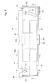
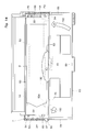
- a toner replenishing device illustrated there comprises a development housing designated entirely by the numeral 2, and a toner cartridge 4 to be mounted replaceably on the development housing 2.
- the development housing 2 constitutes a part of the development housing of an entire developing device (not shown).
- the developing device comprises the development housing 2 which is a container accommodating a toner and being supplied with a toner from the toner cartridge 4; agitating/conveying means (not shown) for agitating and conveying the toner accommodated in the development housing 2 to other development housing (not shown; constituting a developing chamber); and developer applicator means (not shown) for conveying the toner accommodated in the other development housing to a developing region and applying it to an electrostatic photoconductor.
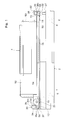
- the development housing 2 comprises a container elongated in the width direction (in a right-and-left direction in Fig. 2) and integrally molded from a suitable plastic material.
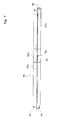
- the development housing 2 has a nearly arcuate bottom wall 6, vertical walls 7 and 8 formed at both ends in the width direction, and an acceptance opening 10 for a toner formed in an upper part thereof.
- the acceptance opening 10 is substantially rectangular when viewed from above. In both side parts in the width direction of its upper end and in a rear part (lower part in Fig. 2) in the front-to-back direction (in the up-and-down direction in Fig. 2), substantially horizontally extending upper surface portions 12, 14 and 16, respectively, are formed along the upper edge of the acceptance opening 10.
- the upper surface portions 12 and 14 are positioned on one side (left side in Fig. 2) and the other side (right side in Fig. 2), respectively, of the development housing 2, while the upper surface portion 16 is positioned in a rear part of the development housing 2.
- the upper surface portions 12, 14 and 16 are positioned on substantially the same horizontal plane.
- a front part (upper part in Fig. 2) of the upper end of the acceptance opening 6 is defined by a front wall 18 extending linearly in the width direction. Between the front wall 18 and the upper end of a front part of the bottom wall 6, a predetermined gap is formed so that a toner is supplied through the gap by the agitating/conveying means (not shown) mounted above the bottom wall 6 into the other development housing (not shown) disposed forward of the gap.
- the seal members 20, 22 and 24 are mounted by adhesion.
- the seal members 20, 22 and 24 each have a predetermined thickness, are elongated and rectangular, and are formed of sponge.
- a concavity 28 extending in the width direction is formed, and a seal member 29 composed of sponge (omitted in Fig. 5) is mounted in the concavity 28.
- the upper surface portion 16 positioned at the upstream end in the mounting direction of the toner cartridge 4 (the direction from below to above in Fig. 2) and/or the seal member 24 mounted thereon are or is preferably inclined such that their or its rear parts or part partially lower or lowers rearward.
- This constitution has the function to smoothly perform the mounting or insertion of the toner cartridge 4 or shutter member 80 to be described later on.
- an end wall 26 is formed at a rear part of the development housing 2.
- the end wall 26 extends downward from the upper surface portion 16, and extends linearly in the width direction.
- a substantially rectangular notch 27 is formed near the other side part in the width direction of the end wall 26, .
- the notch 27 is disposed to temporarily regulate the operating position of the shutter member 80 to be described later on.
- channel-like guide grooves 30 and 32 guide means for smooth mounting and removal of the toner cartridge 4 to be described later on, are formed so as to extend in the front-to-back direction.
- the open portions of the guide grooves 30 and 32 face each other.
- the guide groove 30 includes a side wall 34 extending vertically upward from an outer side part of the upper surface portion 12, and an upper wall 35 extending inward from the upper end of the side wall 34.
- the upper wall 35 includes two upper walls 35a and 35b having different heights, with the forward upper wall 35a being formed at a lower level than the rearward upper wall 35b.
- the guide groove 32 includes a side wall 36 extending vertically upward from an outer side part of the upper surface portion 14, and an upper wall 38 extending inward from the upper end of the side wall 36.
- the upper wall 38 also includes two upper walls 38a and 38b having different heights, with the forward upper wall 38a being formed at a lower level than the rearward upper wall 38b.
- an engaged hole 37 is formed for constituting engaged means.
- the engaged hole 37 is rectangular, and its lower end face is positioned on substantially the same plane as the upper surface portion 12. As shown in Figs. 2 and 13, the vertical surface of the rear side of the engaged hole 37 has an incline surface 39 formed in a laterally outer part of the development housing 2.
- stop means (lock means) 40 is disposed for inhibiting the release of the toner cartridge 4 mounted on the development housing 2.
- the stop means 40 as shown in Figs. 5 and 16, is formed on the end wall 26, and comprises a box portion 42 open upward, a lock claw member 44 disposed so as to be movable up and down in the box portion 42, and a spring 46 for urging the lock claw member 44 upward.
- the box portion 42 protrudes rearward in a rectangular form when viewed from above.
- the lock claw member 44 is always urged by the spring 46 to an operating position at which it protrudes upward in a predetermined amount from the upper surface portion 16.
- upward movement inhibiting means (not shown) is disposed for regulating the operating position of the lock claw member 44.
- the front end of the lock claw member 44 forms a vertical surface, while its upper end forms an inclined surface lowering rearward.
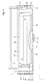
- the toner cartridge 4 is composed of an elongated box-shaped housing 52 having an outlet 50 for a toner in a lower part thereof, and a lower cover member 54 having a flat plate-shaped body fixed below the housing 52.
- the housing 52 and the lower cover member 54 are each integrally molded from a suitable plastic material, and are bonded together by high frequency welding.
- the outlet 50 substantially rectangular is sealed with a sheet member bonded to a flat surface formed around the lower end thereof.
- the sheet member is folded back at one end in the width direction.
- the other end thereof extending in a form overlapping the bonded area is connected to a rotating shaft (not shown) disposed rotatably in one side part of the housing 52.
- the lower cover member 54 is fixed to the housing 52 so as to cover the sheet member from below. In the lower cover member 54, an outlet aligning with the outlet 50 is formed, although this is not clearly shown.
- the outlet 50 is sealed with the sheet member.
- a toner is filled into the toner cartridge 4 through a through-hole 53 formed in the housing 52.
- the through-hole 53 is closed with a closure member (not shown).
- the toner cartridge 4 is mounted at a required position of the development housing 2 as will be described later on.
- the sheet member is stripped off to unseal the outlet 50.
- the stripping of the sheet member is performed by turning a handle H (see a two-dot chain line in Fig. 2) connected detachably to the above-mentioned rotating shaft to wind the sheet member about the rotating shaft.
- a substantially rectangular flange portion is formed at the lower end peripheral edge of the toner cartridge 4 composed of the housing 52 and the lower cover member 54.
- the flange portion extending substantially horizontally and having a flat lower surface comprises a flange portion 56 extending in one side part in the width direction, a flange portion 58 extending in the other side part in the width direction, a flange portion 60 extending in a front part, and a flange portion 62 extending in a rear part.
- two engaging protrusions 64 and 66 are formed with spacing in the front-to-back direction.
- the forward engaging protrusion 64 is formed at a lower level than the rearward engaging protrusion 66.
- the engaging protrusions 64 and 66 are formed slightly inward of the flange portion 56.
- two engaging protrusions 70 and 72 are formed with spacing in the front-to-back direction.
- the forward engaging protrusion 70 is formed at a lower level than the rearward engaging protrusion 72.
- the engaging protrusions 70 and 72 are formed slightly inward of the flange portion 58.
- a projection 61 is formed which projects rearward (see Fig. 2).
- This projection 61 has a rectangular engaged hole 63 (see Figs. 2 and 16). With this engaged hole 63, the lock claw 44 mounted on the development housing 2 engages when the toner cartridge 4 is mounted on the development housing 2. Thus, the movement of the toner cartridge 4 in the releasing direction is inhibited.
- the flange portion 56 of the so constituted toner cartridge 4 is moved forward along the guide groove 30 of the development housing 2, and the flange portion 58 of the toner cartridge 4 is likewise moved forward along the guide groove 32 of the development housing 2.
- the toner cartridge 4 moves such that its lower surface traverses the upper end of the acceptance opening 10 of the development housing 2.
- the toner cartridge 4 is mounted removably on the development housing 2.
- the outlet 50 of the toner cartridge 4 is aligned with the acceptance opening 10.
- the lower engaging protrusion 64 of the flange portion 56 is contacted with the lower-level upper wall 35a of the guide groove 30, while the higher engaging protrusion 66 is contacted with the higher-level upper wall 35b.
- the lower engaging protrusion 70 of the flange portion 58 is contacted with the lower-level upper wall 38a of the guide groove 32, while the higher engaging protrusion 72 is contacted with the higher-level upper wall 38b.
- the flange portion 60 extending in the front part of the toner cartridge 4 is pressed against the seal member 29 disposed on the front wall 18.
- the flange portion 56 extending in one side part of the flange portion 60, the flange portion 58 extending in the other side part, and the flange portion 62 extending in the rear part, respectively, are brought into intimate contact with the upper surface portions 12, 14 and 16 of the development housing 2 via the seal members 20, 22 and 24.
- the lock claw 44 disposed in the development housing 2 is engaged with the engaged hole 63 of the toner cartridge 4 (see Fig. 16), whereby the movement of the toner cartridge 4 in the releasing direction is inhibited. Then, as has been described earlier, the outlet 50 of the toner cartridge 4 is unsealed to supply the toner in the toner cartridge 4 through the acceptance opening 10.
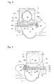
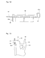
- a shutter member 80 is used.
- the shutter member 80 which may be integrally molded from a suitable plastic material, such as ABS resin, is substantially rectangular when viewed from above.
- a flange portion 82 is formed so as to extend in a substantially rectangular form when viewed from above.
- the flange portion 82 extends downward, and its height is constant.
- a flange portion 82a positioned at the front end extends linearly in the width direction, but has an inward concavity 82b in the middle in the width direction thereof. This concavity 82b is formed to avoid interference with the box portion 42 formed on the end wall 26 of the development housing 2 when the shutter member 80 is inserted between the toner cartridge 4 and the development housing 2, as will be described later on.
- guide grooves 84 and 86 are formed in a channel-like form.
- a flange portion 87 extending upward is formed in a rear end part of the shutter member 80.
- the flange portion 87 extends linearly in the width direction, but has a rearwardly projecting projection 88 in the middle in the width direction thereof.
- This projection 88 is formed to avoid interference with the projection 61 of the toner cartridge 4 when the toner cartridge 4 is removed from the development housing 2 and accepted on the shutter member 80, as will be described later on.
- a small engaging protrusion 89 is formed near the projection 88 on the upper surface of the shutter member 80.
- This protrusion 89 is formed to releasably engage the engaged hole 63 formed in the projection 61 of the toner cartridge 4 when the toner cartridge 4 is accepted on the shutter member 80.
- a grip portion 87a is formed for smoothly performing a turning operation for the shutter member 80 to be described later on.
- the grip portion 87a is formed by projecting the flange portion 87 rearward in a rectangular form, and has an upper surface and a rear surface each with a plurality of protuberances (see Fig. 12).
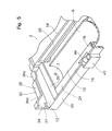
- a hook portion 90 is formed for constituting engaging means.
- the hook portion 90 is releasably engaged with the engaged hole 37 formed in the rear part of the side wall 34 of the development housing 2.
- the hook portion 90 protrudes forward from the top of the flange portion 82a, then extends laterally outward of the one side part, and further extends rearward (in a direction opposite to the inserting direction).
- an inclined surface 90a is formed which corresponds to the inclined surface 39 formed in the engaged hole 37 (see Fig. 13).
- an insertion portion 92 is further formed which protrudes forward substantially from the top of the flange portion 82a and extends widthwise.
- the insertion portion 92 defines the front end of the shutter member 80.
- the hook portion 90 and the insertion portion 92 comprise a plate-like portion formed so as to protrude forward and substantially horizontally from the upper end of the flange portion 82a.
- the insertion portion 92 has a lower surface inclined so as to ascend forward (in the inserting direction) (see Figs. 11 and 12) in order to smoothly perform an inserting operation to be described later on.
- an engaging piece 94 is formed which constitutes engaging means.
- the engaging piece 94 comprises a plate-like portion projecting forward and nearly horizontally from the flange portion 82a, and an upward engaging projection formed at the front end of the plate-like portion.
- the engaging piece 94 is releasably engaged with the notch 27 formed in the end wall 26 of the development housing 2 when the shutter member 80 is located at the operating position as will be described later on.
- the engaging projection is inclined in its front and rear surfaces for relatively easy engagement with and release from the notch 27.
- the upper surface of the shutter member 80 bears a mark which indicates an operating procedure for locating the shutter member 80 at the operating position to be described later on.
- This mark comprises a first arrow 100 directed toward the hook portion 90, and a second arrow 102 headed in the direction of turning toward the inserting direction.
- the second arrow 102 is curved to show a turn.
- the arrows 100 and 102 are created by forming relatively shallow concavities in the shutter member 80 (see Fig. 10).
- the first arrow 100 there is formed the number 1, a symbol showing that an operation for engaging the hook portion 90 with the engaged hole 37 of the development housing 2 should be performed in the first step.
- the number 2 a symbol showing that an operation for turning the shutter member 80 in the inserting direction should be performed in the second step.
- These numbers 1 and 2 are formed from relatively low projections. These symbols may be symbols other than numerals, e.g., alphabets such as A and B. These symbols may also be formed not in the arrows 100 and 102, but near them.
- the upper surface of the shutter member 80 is formed in a substantially horizontal, flat form as a whole, except for the arrows 100 and 102 formed thereon, or other concavities (their explanations are omitted), the guide grooves 84 and 86 or the flange portion 87.
- the closest site to the most distant site, relative to the fulcrum, of the insertion portion 92, at the front end of the shutter member 80 is gradually inserted between the lower surface of the toner cartridge 4 and the upper surface portion of the development housing 2 (mainly, the upper surface portion 16) (more precisely, the seal member 24).
- the force of the inserting operation is markedly reduced, although the seal member 24 is elastically deformed.
- the hook portion 90 is engaged with the engaged hole 37, and the shutter member 80 is turned about the engaged hole 37.
- the position of the shutter member 80 is regulated automatically properly, without the need to perform its alignment in the width direction relative to the development housing 2.
- the flange portion 82a formed at the front end of the shutter member 80 is contacted with the end wall 26 of the development housing 2, whereby the above-mentioned turn is inhibited.
- the mere execution of the turning operation ensures the reliable positioning of the shutter member 80 at the operating position (see Figs. 14 and 15).
- the operating position of the shutter member 80 i.e., the insertion depth of the front end of the shutter member 80, can be confirmed even more easily.
- the release of the lock means is performed reliably.
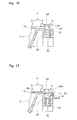
- the insertion portion 92 of the shutter member 80 is inserted, over its entire width, between the lower surface of the toner cartridge 4 and the upper surface portion of the development housing 2. As indicated by a solid line in Fig. 13, the hook portion 90 is completely engaged with the engaged hole 37. During the turning operation in which the shutter member 80 is located at the operating position, the insertion portion 92 pushes the lock claw member 44 provided in the development housing 2 downward against the urging force of the spring 46. Thereby, the locking action on the toner cartridge 4 is cleared (see Fig. 17).
- the engaging piece 94 of the shutter member 80 is releasably engaged transiently with the notch 27 formed in the end wall 26 of the development housing 2 (Fig. 15). This is convenient because the positioning of the shutter member 80 at the operating position can be easily confirmed, and that makes it possible to perform the removal of the toner cartridge 4 (to be described later on) easily and precisely.
- the shutter member 80 is inserted between the lower surface of the toner cartridge 4 and the upper surface portion of the development housing 2 by the turning operation.
- a twist as in the prior art does not occur, and the inserting operation is carried out easily and smoothly.
- the upper surface of the shutter member 80 bears the first arrow 100 and the second arrow 102, the symbols showing the sequence of steps for positioning the shutter member 80 at the operating position. Hence, the sequence of steps to be done can be confirmed visually, and the engaging operation and the inserting operation (turning operation) can be performed easily and accurately.
- the toner cartridge 4 is withdrawn from the development housing 2, whereupon the flange portions 56 and 58 of the toner cartridge 4 are released from the guide grooves 30 and 32 of the development housing 2. Then, the toner cartridge 4 is guided by the guide grooves 84 and 86 of the shutter member 80 to be moved onto the shutter member 80. As noted earlier, the position of the shutter member 80 is temporarily restrained relative to the development housing 2, because the engaging piece 94 of the shutter member 80 is engaged with the notch 27 of the end wall 26 of the development housing 2. Thus, the above withdrawal, i.e. removal of the toner cartridge 4 from the development housing 2 can be performed easily and accurately in a stable manner.
- the outlet 50 of the toner cartridge 4 is closed with the shutter member 80.
- the engaged hole 63 formed in the projection 61 of the toner cartridge 4 is releasably engaged with the engaging protrusion 89 of the shutter member 80.
- the shutter member of the invention is applied not only to the toner replenishing device of the above-described type, but also to other types of toner replenishing devices, such as a toner replenishing device of the type in which a toner cartridge is removably mounted on a toner hopper (container) located at a position apart from a development housing.
- the hook portion 90 i.e., engaging means
- the engaged hole 37 i.e., engaged means
- the engaging piece 94 other engaging means, is formed in the shutter member 80, while the notch 27, other engaged means, is formed in the end wall 26 of the development housing 2; however, they may be formed vice versa.
Landscapes
- Physics & Mathematics (AREA)
- General Physics & Mathematics (AREA)
- Dry Development In Electrophotography (AREA)
Applications Claiming Priority (3)
| Application Number | Priority Date | Filing Date | Title |
|---|---|---|---|
| JP306839/96 | 1996-11-18 | ||
| JP30683996 | 1996-11-18 | ||
| JP30683996A JP3284334B2 (ja) | 1996-11-18 | 1996-11-18 | シャッタ部材及びこれを使用するトナー補給装置 |
Publications (3)
| Publication Number | Publication Date |
|---|---|
| EP0844537A2 true EP0844537A2 (de) | 1998-05-27 |
| EP0844537A3 EP0844537A3 (de) | 1998-12-02 |
| EP0844537B1 EP0844537B1 (de) | 2002-01-02 |
Family
ID=17961885
Family Applications (1)
| Application Number | Title | Priority Date | Filing Date |
|---|---|---|---|
| EP97308647A Expired - Lifetime EP0844537B1 (de) | 1996-11-18 | 1997-10-29 | Tonernachfüllvorrichtung, Verschluss für Tonerbehälter und Tonerbehälter |
Country Status (9)
| Country | Link |
|---|---|
| US (1) | US5812914A (de) |
| EP (1) | EP0844537B1 (de) |
| JP (1) | JP3284334B2 (de) |
| KR (1) | KR19980042400A (de) |
| CN (1) | CN1182897A (de) |
| AU (1) | AU4368297A (de) |
| DE (1) | DE69709837T2 (de) |
| ID (1) | ID18924A (de) |
| TW (1) | TW370634B (de) |
Cited By (1)
| Publication number | Priority date | Publication date | Assignee | Title |
|---|---|---|---|---|
| EP1154333A3 (de) * | 2000-05-08 | 2001-11-28 | Ricoh Company, Ltd. | Bilderzeugungsgerät mit leicht auswechselbarem Tonerbehälter und eine Tonerzuführpumpe |
Families Citing this family (15)
| Publication number | Priority date | Publication date | Assignee | Title |
|---|---|---|---|---|
| TW517179B (en) * | 1999-03-29 | 2003-01-11 | Canon Kk | Developer replenishing container, cartridge and image forming apparatus |
| JP3450741B2 (ja) * | 1999-03-29 | 2003-09-29 | キヤノン株式会社 | トナー補給容器 |
| JP3445202B2 (ja) * | 1999-03-29 | 2003-09-08 | キヤノン株式会社 | トナー補給容器 |
| US6438328B1 (en) | 2000-11-08 | 2002-08-20 | Xerox Corporation | Reversible shutter lockout feature |
| JP3427299B2 (ja) * | 2000-11-30 | 2003-07-14 | 京セラミタ株式会社 | トナー補給装置及びそのトナーカートリッジ |
| JP3658381B2 (ja) * | 2002-06-04 | 2005-06-08 | キヤノン株式会社 | 電子写真画像形成装置およびプロセスカートリッジ |
| JP2006030574A (ja) * | 2004-07-15 | 2006-02-02 | Toshiba Corp | トナーカートリッジ及びその脱着機構 |
| KR100756044B1 (ko) * | 2005-08-29 | 2007-09-07 | 삼성전자주식회사 | 현상제통과 현상제 공급장치 및 이를 가지는 화상형성장치 |
| KR100895801B1 (ko) * | 2005-10-04 | 2009-05-08 | 가부시키가이샤 리코 | 분체 공급 장치, 화상 형성 장치 및 감시 장치 |
| JP5067865B2 (ja) * | 2007-02-21 | 2012-11-07 | キヤノン株式会社 | 現像剤補給容器及び画像形成装置 |
| JP2010054638A (ja) * | 2008-08-27 | 2010-03-11 | Sharp Corp | トナー搬送ユニットおよびこれを備える画像形成装置 |
| NZ601975A (en) | 2010-03-10 | 2013-06-28 | Ricoh Co Ltd | Toner container with an identifying non compatible shape part |
| JP5435116B2 (ja) | 2012-03-15 | 2014-03-05 | 株式会社リコー | 粉体収納容器、その粉体収納容器から現像剤を補給する粉体補給装置、およびそれが搭載される画像形成装置 |
| US9158269B2 (en) * | 2013-09-03 | 2015-10-13 | Samsung Electronics Co., Ltd. | Electrophotographic image forming apparatus having a stable connection of a developer cartridge and toner cartridge |
| JP7764238B2 (ja) * | 2021-12-23 | 2025-11-05 | キヤノン株式会社 | 現像剤容器および画像形成システム |
Family Cites Families (7)
| Publication number | Priority date | Publication date | Assignee | Title |
|---|---|---|---|---|
| JPS63179377A (ja) * | 1987-01-20 | 1988-07-23 | Nec Corp | トナ−補給装置 |
| JPH03158872A (ja) * | 1989-11-16 | 1991-07-08 | Asahi Optical Co Ltd | トナーの補給方法 |
| JPH03245172A (ja) * | 1990-02-19 | 1991-10-31 | Nippon Kentek Kaisha Ltd | トナー補給容器及びトナー補給容器を固定する装置 |
| JPH03119860U (de) * | 1990-03-20 | 1991-12-10 | ||
| US5294963A (en) * | 1991-04-19 | 1994-03-15 | Mita Industrial Co., Ltd. | Toner cartridge having opening for discharging toner sealed with sealing member and method of stripping sealing member |
| US5337125A (en) * | 1991-05-29 | 1994-08-09 | Mita Industrial Co., Ltd. | Toner feeding device |
| JP2907625B2 (ja) * | 1992-02-03 | 1999-06-21 | キヤノン株式会社 | 現像剤補給容器 |
-
1996
- 1996-11-18 JP JP30683996A patent/JP3284334B2/ja not_active Expired - Fee Related
-
1997
- 1997-10-24 US US08/957,708 patent/US5812914A/en not_active Expired - Lifetime
- 1997-10-29 EP EP97308647A patent/EP0844537B1/de not_active Expired - Lifetime
- 1997-10-29 DE DE69709837T patent/DE69709837T2/de not_active Expired - Fee Related
- 1997-11-03 AU AU43682/97A patent/AU4368297A/en not_active Abandoned
- 1997-11-13 KR KR1019970059865A patent/KR19980042400A/ko not_active Withdrawn
- 1997-11-15 TW TW086117078A patent/TW370634B/zh active
- 1997-11-18 CN CN97120180A patent/CN1182897A/zh active Pending
- 1997-11-18 ID IDP973701A patent/ID18924A/id unknown
Cited By (3)
| Publication number | Priority date | Publication date | Assignee | Title |
|---|---|---|---|---|
| EP1154333A3 (de) * | 2000-05-08 | 2001-11-28 | Ricoh Company, Ltd. | Bilderzeugungsgerät mit leicht auswechselbarem Tonerbehälter und eine Tonerzuführpumpe |
| US6591077B2 (en) | 2000-05-08 | 2003-07-08 | Ricoh Company, Ltd. | Image forming apparatus and toner container therefor |
| CN100385347C (zh) * | 2000-05-08 | 2008-04-30 | 株式会社理光 | 图像形成装置及其调色剂容器 |
Also Published As
| Publication number | Publication date |
|---|---|
| ID18924A (id) | 1998-05-20 |
| DE69709837D1 (de) | 2002-02-28 |
| AU4368297A (en) | 1998-05-21 |
| JPH10149021A (ja) | 1998-06-02 |
| TW370634B (en) | 1999-09-21 |
| CN1182897A (zh) | 1998-05-27 |
| EP0844537B1 (de) | 2002-01-02 |
| US5812914A (en) | 1998-09-22 |
| JP3284334B2 (ja) | 2002-05-20 |
| EP0844537A3 (de) | 1998-12-02 |
| KR19980042400A (ko) | 1998-08-17 |
| DE69709837T2 (de) | 2002-09-19 |
Similar Documents
| Publication | Publication Date | Title |
|---|---|---|
| EP0844537B1 (de) | Tonernachfüllvorrichtung, Verschluss für Tonerbehälter und Tonerbehälter | |
| JP3267879B2 (ja) | トナー補給装置およびトナーカートリッジ | |
| US6014536A (en) | Toner supply mechanism having locking means for locking a shutter member and a toner supply container having projections for releasable locking a hopper shutter member | |
| KR0132139B1 (ko) | 현상제 보충용 카아트리지 | |
| CN201107564Y (zh) | 色调剂卡盒及图像形成装置 | |
| JPH0582581B2 (de) | ||
| JPH0720681Y2 (ja) | 現像装置の現像剤供給装置 | |
| JP2008112198A (ja) | トナー供給装置およびシャッタ構造 | |
| JP2838275B2 (ja) | 静電潜像現像装置及びそれに使用されるトナーカートリッジ | |
| EP0816936B1 (de) | Tonernachfüllvorrichtung in einem bilderzeugenden Gerät und zugehörige Tonerkassette | |
| JP2002082519A (ja) | トナー粉末補充機構 | |
| JP3326582B2 (ja) | 現像剤補給装置 | |
| JPH0622851Y2 (ja) | トナー補給装置 | |
| JP3326581B2 (ja) | 現像剤補給装置 | |
| JPS60198567A (ja) | トナ−補充装置 | |
| JP2662869B2 (ja) | 電子写真装置 | |
| KR930010871B1 (ko) | 토너카트리지 | |
| JP2000029292A (ja) | トナー供給装置 | |
| JP3136555B2 (ja) | 現像剤補給装置 | |
| JP3235048B2 (ja) | 画像形成機のトナー補給装置 | |
| JPH0733245Y2 (ja) | カートリッジ梱包箱 | |
| JP3235047B2 (ja) | 画像形成機のトナー補給装置 | |
| JPH02196260A (ja) | 電子写真装置のトナーカートリッジ | |
| KR970001197B1 (ko) | 현상제 보충기구 | |
| JPH0642104B2 (ja) | トナ−補給用カ−トリツジ |
Legal Events
| Date | Code | Title | Description |
|---|---|---|---|
| PUAI | Public reference made under article 153(3) epc to a published international application that has entered the european phase |
Free format text: ORIGINAL CODE: 0009012 |
|
| AK | Designated contracting states |
Kind code of ref document: A2 Designated state(s): CH DE GB LI |
|
| AX | Request for extension of the european patent |
Free format text: AL;LT;LV;RO;SI |
|
| PUAL | Search report despatched |
Free format text: ORIGINAL CODE: 0009013 |
|
| AK | Designated contracting states |
Kind code of ref document: A3 Designated state(s): AT BE CH DE DK ES FI FR GB GR IE IT LI LU MC NL PT SE |
|
| AX | Request for extension of the european patent |
Free format text: AL;LT;LV;RO;SI |
|
| 17P | Request for examination filed |
Effective date: 19990420 |
|
| AKX | Designation fees paid |
Free format text: AT BE CH LI |
|
| RBV | Designated contracting states (corrected) |
Designated state(s): CH DE GB LI |
|
| REG | Reference to a national code |
Ref country code: DE Ref legal event code: 8566 |
|
| RAP1 | Party data changed (applicant data changed or rights of an application transferred) |
Owner name: KYOCERA MITA CORPORATION |
|
| GRAG | Despatch of communication of intention to grant |
Free format text: ORIGINAL CODE: EPIDOS AGRA |
|
| RTI1 | Title (correction) |
Free format text: TONER REPLENISHING DEVICE, SHUTTER MEMBER FOR TONER CARTRIDGE, AND TONER CARTRIDGE |
|
| RTI1 | Title (correction) |
Free format text: TONER REPLENISHING DEVICE, SHUTTER MEMBER FOR TONER CARTRIDGE, AND TONER CARTRIDGE |
|
| 17Q | First examination report despatched |
Effective date: 20010516 |
|
| GRAG | Despatch of communication of intention to grant |
Free format text: ORIGINAL CODE: EPIDOS AGRA |
|
| GRAH | Despatch of communication of intention to grant a patent |
Free format text: ORIGINAL CODE: EPIDOS IGRA |
|
| GRAH | Despatch of communication of intention to grant a patent |
Free format text: ORIGINAL CODE: EPIDOS IGRA |
|
| GRAA | (expected) grant |
Free format text: ORIGINAL CODE: 0009210 |
|
| REG | Reference to a national code |
Ref country code: GB Ref legal event code: IF02 |
|
| AK | Designated contracting states |
Kind code of ref document: B1 Designated state(s): CH DE GB LI |
|
| REG | Reference to a national code |
Ref country code: CH Ref legal event code: NV Representative=s name: ISLER & PEDRAZZINI AG Ref country code: CH Ref legal event code: EP |
|
| REF | Corresponds to: |
Ref document number: 69709837 Country of ref document: DE Date of ref document: 20020228 |
|
| PLBE | No opposition filed within time limit |
Free format text: ORIGINAL CODE: 0009261 |
|
| STAA | Information on the status of an ep patent application or granted ep patent |
Free format text: STATUS: NO OPPOSITION FILED WITHIN TIME LIMIT |
|
| 26N | No opposition filed | ||
| PGFP | Annual fee paid to national office [announced via postgrant information from national office to epo] |
Ref country code: GB Payment date: 20051026 Year of fee payment: 9 |
|
| PGFP | Annual fee paid to national office [announced via postgrant information from national office to epo] |
Ref country code: DE Payment date: 20051027 Year of fee payment: 9 Ref country code: CH Payment date: 20051027 Year of fee payment: 9 |
|
| PG25 | Lapsed in a contracting state [announced via postgrant information from national office to epo] |
Ref country code: LI Free format text: LAPSE BECAUSE OF NON-PAYMENT OF DUE FEES Effective date: 20061031 Ref country code: CH Free format text: LAPSE BECAUSE OF NON-PAYMENT OF DUE FEES Effective date: 20061031 |
|
| PG25 | Lapsed in a contracting state [announced via postgrant information from national office to epo] |
Ref country code: DE Free format text: LAPSE BECAUSE OF NON-PAYMENT OF DUE FEES Effective date: 20070501 |
|
| REG | Reference to a national code |
Ref country code: CH Ref legal event code: PL |
|
| GBPC | Gb: european patent ceased through non-payment of renewal fee |
Effective date: 20061029 |
|
| PG25 | Lapsed in a contracting state [announced via postgrant information from national office to epo] |
Ref country code: GB Free format text: LAPSE BECAUSE OF NON-PAYMENT OF DUE FEES Effective date: 20061029 |