EP0844702A2 - Raccordement de conduite - Google Patents
Raccordement de conduite Download PDFInfo
- Publication number
- EP0844702A2 EP0844702A2 EP97108196A EP97108196A EP0844702A2 EP 0844702 A2 EP0844702 A2 EP 0844702A2 EP 97108196 A EP97108196 A EP 97108196A EP 97108196 A EP97108196 A EP 97108196A EP 0844702 A2 EP0844702 A2 EP 0844702A2
- Authority
- EP
- European Patent Office
- Prior art keywords
- line
- connection
- cylinder
- cylinders
- intermediate line
- Prior art date
- Legal status (The legal status is an assumption and is not a legal conclusion. Google has not performed a legal analysis and makes no representation as to the accuracy of the status listed.)
- Granted
Links
- 230000000295 complement effect Effects 0.000 claims description 2
- 230000007935 neutral effect Effects 0.000 claims 1
- 230000009286 beneficial effect Effects 0.000 description 2
- 230000003247 decreasing effect Effects 0.000 description 2
- 238000010276 construction Methods 0.000 description 1
- 230000001419 dependent effect Effects 0.000 description 1
- 238000011161 development Methods 0.000 description 1
- 230000018109 developmental process Effects 0.000 description 1
- 238000010586 diagram Methods 0.000 description 1
- 239000000835 fiber Substances 0.000 description 1
- 239000012530 fluid Substances 0.000 description 1
- 239000000463 material Substances 0.000 description 1
Images



Classifications
-
- H—ELECTRICITY
- H01—ELECTRIC ELEMENTS
- H01R—ELECTRICALLY-CONDUCTIVE CONNECTIONS; STRUCTURAL ASSOCIATIONS OF A PLURALITY OF MUTUALLY-INSULATED ELECTRICAL CONNECTING ELEMENTS; COUPLING DEVICES; CURRENT COLLECTORS
- H01R35/00—Flexible or turnable line connectors, i.e. the rotation angle being limited
- H01R35/02—Flexible line connectors without frictional contact members
- H01R35/025—Flexible line connectors without frictional contact members having a flexible conductor wound around a rotation axis
-
- H—ELECTRICITY
- H01—ELECTRIC ELEMENTS
- H01R—ELECTRICALLY-CONDUCTIVE CONNECTIONS; STRUCTURAL ASSOCIATIONS OF A PLURALITY OF MUTUALLY-INSULATED ELECTRICAL CONNECTING ELEMENTS; COUPLING DEVICES; CURRENT COLLECTORS
- H01R31/00—Coupling parts supported only by co-operation with counterpart
Definitions
- the invention relates to a line connection according to the preamble of the claim 1.
- Line connections of this type are used to connect two lines together to be connected when used relative to each other about a common axis be moved; frequently, but not always, only one of the lines is moved while the other is stationary.
- An intermediate line is used to connect the two lines. One end of which is at a first connection to the first line and at one second connection connected to the second line. In cases where only a fixed to be connected to a moving line, one of the connections is fixed and the others movable. If the intermediate line is flexible, it will be used if necessary guided by a guide device.
- the object of the invention is thus seen in a line connection of the beginning to propose the type mentioned the relative rotation of two lines or connections by a full rotation of 360 ° or slightly more.
- the new line connection is based on the principle, instead of the lines to be connected and the intermediate line to provide two lines or intermediate lines, which are functionally, but not geometrically, connected in parallel. This allows as will be described later, a mirror-symmetrical arrangement of the intermediate line and the additional intermediate line provided according to the invention in two to a certain extent opposite loops, which means that in each movement phase the Intermediate line and the additional intermediate line are stressed so that highly flexible cables can be used.
- two coaxial cylinders namely an inner cylinder and an outer cylinder, are provided, that can rotate relative to each other.
- a freely rotatable planet gear with a diameter in the circular ring between fits the two cylinders and its axis is parallel to the axis of the cylinders is.
- the first line is at a first connection with one end of the intermediate line connected; a first branch line branched off from it is connected to another Connection connected to one end of the additional branch line.
- the two mentioned Ports are located on one of the cylinders.
- To the other end of the intermediate line if the second line is connected to another connection, and to the other end of the auxiliary link is the last connection second branch line connected.
- the latter two connections are on the other the cylinder arranged as the two ports mentioned above.
- the intermediate line and the Additional intermediate line as well as the planet gear symmetrical to a plane of symmetry arranged by the axis of the cylinder and the one in the zero position Axis of the planet gear is defined.
- the intermediate line runs from its first connection at one of the cylinders along this cylinder up to the planet gear this along 180 ° and sits along the other cylinder until it is connected to it Cylinder on; the additional intermediate line runs accordingly from the connection on one Cylinder to the planet gear, half round it, complementary to the intermediate line, and sits along the other cylinder up to her on that cylinder arranged connection.
- the line connection according to the invention described above is not only because of the Possibility to use highly flexible cables and thus also large angles up to 360 ° or more to brush, beneficial.
- the symmetrical arrangement is also with regard to the torque advantageous, there are no restoring forces and the friction of the whole arrangement is minimal.
- Another, in some cases significant advantage of The line connection according to the invention can be seen in the fact that it is neither inward still protrudes to the outside through a hollow cylinder, which through the inner and corresponds to the outer cylinder limited space, so that others in the middle in particular Components are housed, preferably those that are in a coaxial relationship stand for the relative movement of the two cylinders.
- connection locations are determined by the desired total angle of rotation and of course also determined by the diameter ratio of the two cylinders.
- a rotation angle of approx. 200 ° can be achieved by choosing the diameter ratio in the approximate range of 1: 2 in the zero position, the connections on one of the Cylinder be arranged approximately diametrically, while the connections on the other Cylinders can collapse in the plane of symmetry.
- the guide surfaces that is, the inner Circumferential surface of the outer cylinder, the outer circumferential surface of the inner cylinder and the outer circumferential surface of the planet gear extending in the circumferential direction Contain guide grooves or ribs; also corresponding cylinder bottoms or -Lids can perform management functions.
- the new cable connection is also very suitable for small angles of rotation, it is particularly advantageous if a relative total angle of more than 360 °, that is approximately 400 °, is to be brushed so that there is a rotation from the zero position in each direction of rotation by about 200 ° in the extreme positions.
- a stop element can be on one of the cylinders be provided.
- Two fixed stops are attached to the other of the cylinders; of the The angular distance of these fixed stops is equal to the total angle of rotation minus 360 °.
- In the middle between these fixed stops is on the same cylinder between the fixed stops freely pivotable stop lever arranged.
- the fixed stops serve to the stop lever, which interacts with the stop plate in extreme positions, each to position according to extreme position.
- the stop lever is located in one extreme position between one fixed stop and one surface of the stop element, in the other extreme position, the stop lever is between the other fixed stop and the opposite surface of the stop element.
- this stop element can also be designed as a lever.
- the line connections according to the invention are suitable for connecting lines of all kinds such as fluid lines, fiber optic lines and electrical cables, in particular Ribbon cable in the manner of flex prints.
- Fig. 1 shows an embodiment of a line connection according to the prior art.
- the line connection serves to connect line A to another line B , for which purpose an intermediate line C is used.
- the intermediate line C is connected at a connection D to the line A and at a connection E to the line B.
- the connection E must move by the required angle of rotation or on a corresponding circular line from one extreme position to the other extreme position, such as it is indicated in Fig. 1 by arrows starting from E.
- the connection E and thus the end of the intermediate line C connected there are guided by means of a guiding device during this movement.
- connection D which is considered to be movable, must rotate from a zero position in both directions of rotation by theoretically by 180 ° or, taking structural conditions into account, by 180 ° , which corresponds to a total rotation angle of over 360 °.
- Fig. 1 makes it clear that - as described above - the previously known line connections in the range of about 50 ° in total, but are not suitable for larger angles of rotation.
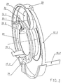
- the line connection 10 serves to connect electrical lines. It has an intermediate line 12.1 and an additional intermediate line 12.2 , both in the form of flex prints.
- An inner cylinder 20 and an outer cylinder 22 are provided as a guide device for the intermediate line 12.1 and the additional intermediate line 12.2 , which have a common axis M , about which they can be rotated relative to one another.
- the inner cylinder 20 is fixed, while the outer cylinder 22 is rotatable.
- a freely movable planet gear 24 Arranged between the cylinders 20 and 22 is a freely movable planet gear 24 , which is also attributable to the guide device, the diameter of which essentially corresponds to the radius difference of the two cylinders 20 , 22 and the axis N of which is directed parallel to the axis M.
- the intermediate line 12.1 connects a first line 14.1 to a second line 16.1
- the additional intermediate line 12.2 connects a first branch line 14.2 to a second branch line 16.2.
- One end of the intermediate line 12 is connected to the first line 14.1 at a connection 18.1 and the other end of the branch line 12.1 is connected to the second line 16.1 at a connection 19.1 .
- one end of the additional intermediate line 12.2 is connected to the first branch line 14.2 at a connection 18.2 and the other end of the additional intermediate line 12.2 is connected to the second branch line at a connection 19.2 .
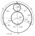
- connections 18.1 and 18.2 are located on the outer cylinder 22 , which is moved in the present exemplary embodiment, and the connections 19.1 and 19.2 are located on the inner cylinder 20, which is fixed in the present exemplary embodiment. It is obvious that in the present configuration the connections 19.1 and 19.1 and thus also the second line 16.1 and the second branch line 16.2 could also be combined.
- the intermediate line 12.1 , the additional intermediate line 12.2 and the planet gear 24 are arranged symmetrically in the zero position of the line connection 10 , specifically with respect to a plane of symmetry S , which is defined by the axis M of the cylinders 20 , 22 and the zero axis N of the planet gear 24 is defined and shown in FIGS . 5A-5C , where it presents itself as a vertical straight line.
- the intermediate line 12.1 extends from the connection 18.1 along the inner wall of the outer cylinder 22 to the planet gear 24 , circles it along its one half and continues along the outer wall of the inner cylinder 20 to the connection 19.1 .
- the additional intermediate line 12.2 runs symmetrically to the connection 18.2 , orbiting the other half of the planet gear 24 , to the connection 19.2 .
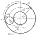
- FIG. 5A shows the movable parts of the line connection 10 in their zero position, while FIG. 5B approximately represents the one extreme position and FIG. 5C approximately the other extreme position of the movable parts of the line connection 10 .
- the mutual angular distance of the fixed stops is 40 ° if it is assumed that the total angle of rotation should be 400 °.
- a stop element 34 is fastened to the outer cylinder 22 . In one extreme position, the stop lever 32 is located between one fixed stop 32.1 and one surface of the stop element 34 , and in the other extreme position the stop lever 32 is located between the other fixed stop 30.2 and the other surface of the stop element 34 .
Landscapes
- Transmission Devices (AREA)
- Cable Accessories (AREA)
- Retarders (AREA)
- Preliminary Treatment Of Fibers (AREA)
- Processing Of Terminals (AREA)
Applications Claiming Priority (3)
| Application Number | Priority Date | Filing Date | Title |
|---|---|---|---|
| CH289696 | 1996-11-25 | ||
| CH289696 | 1996-11-25 | ||
| CH2896/96 | 1996-11-25 |
Publications (3)
| Publication Number | Publication Date |
|---|---|
| EP0844702A2 true EP0844702A2 (fr) | 1998-05-27 |
| EP0844702A3 EP0844702A3 (fr) | 1999-06-02 |
| EP0844702B1 EP0844702B1 (fr) | 2000-01-12 |
Family
ID=4244043
Family Applications (1)
| Application Number | Title | Priority Date | Filing Date |
|---|---|---|---|
| EP97108196A Expired - Lifetime EP0844702B1 (fr) | 1996-11-25 | 1997-05-21 | Raccordement de conduite |
Country Status (5)
| Country | Link |
|---|---|
| US (1) | US5919054A (fr) |
| EP (1) | EP0844702B1 (fr) |
| JP (1) | JPH10199649A (fr) |
| CA (1) | CA2216018A1 (fr) |
| DE (1) | DE59700996D1 (fr) |
Cited By (2)
| Publication number | Priority date | Publication date | Assignee | Title |
|---|---|---|---|---|
| CN108463927A (zh) * | 2016-01-08 | 2018-08-28 | 古河电气工业株式会社 | 旋转连接器装置 |
| CN113800339A (zh) * | 2021-09-16 | 2021-12-17 | 中国电子科技集团公司第三十八研究所 | 一种滑轮式管路自动卷绕装置 |
Families Citing this family (2)
| Publication number | Priority date | Publication date | Assignee | Title |
|---|---|---|---|---|
| US7758364B1 (en) * | 2009-08-04 | 2010-07-20 | Seagate Technology Llc | Rotary positioning |
| EP3467967B1 (fr) * | 2016-05-31 | 2021-11-24 | Alps Alpine Co., Ltd. | Connecteur rotatif |
Family Cites Families (10)
| Publication number | Priority date | Publication date | Assignee | Title |
|---|---|---|---|---|
| FR703931A (fr) * | 1930-01-09 | 1931-05-08 | Maison Breguet | Perfectionnement aux projecteurs lumineux |
| DE1984655U (de) * | 1968-02-21 | 1968-05-02 | Siemens Ag | Anordnung zur elektrisch leitenden verbindung eines beweglichen organs mit einem feststehenden teil. |
| DE1945295B2 (de) * | 1969-09-06 | 1973-02-01 | Kuhna, Fritz, Dipl Ing , 4040 Neuß | Vorrichtung zur energiezuleitung zu auf kreisfoermigen bahnen beweglichen verbrauchern |
| US3601623A (en) * | 1969-09-23 | 1971-08-24 | Bendix Corp | Flex lead assembly having minimum and substantially constant friction and torque |
| JPH0389059U (fr) * | 1989-12-26 | 1991-09-11 | ||
| JPH0389057U (fr) * | 1989-12-26 | 1991-09-11 | ||
| DE4001880A1 (de) * | 1990-01-23 | 1991-07-25 | Gore W L & Ass Gmbh | Anordnung zum fuehren von leitungen |
| US5259775A (en) * | 1990-10-24 | 1993-11-09 | Kabushiki Kaisha Tokai Rika Denki Seisakusho | Flat cable connector |
| JPH04162383A (ja) * | 1990-10-24 | 1992-06-05 | Tokai Rika Co Ltd | ロールコネクタ |
| JP2540916Y2 (ja) * | 1991-12-24 | 1997-07-09 | 古河電気工業株式会社 | 相対的に回転する二部材間の伝送装置 |
-
1997
- 1997-05-21 EP EP97108196A patent/EP0844702B1/fr not_active Expired - Lifetime
- 1997-05-21 DE DE59700996T patent/DE59700996D1/de not_active Expired - Fee Related
- 1997-08-27 US US08/917,759 patent/US5919054A/en not_active Expired - Fee Related
- 1997-10-06 CA CA002216018A patent/CA2216018A1/fr not_active Abandoned
- 1997-10-17 JP JP9284931A patent/JPH10199649A/ja active Pending
Cited By (2)
| Publication number | Priority date | Publication date | Assignee | Title |
|---|---|---|---|---|
| CN108463927A (zh) * | 2016-01-08 | 2018-08-28 | 古河电气工业株式会社 | 旋转连接器装置 |
| CN113800339A (zh) * | 2021-09-16 | 2021-12-17 | 中国电子科技集团公司第三十八研究所 | 一种滑轮式管路自动卷绕装置 |
Also Published As
| Publication number | Publication date |
|---|---|
| EP0844702A3 (fr) | 1999-06-02 |
| JPH10199649A (ja) | 1998-07-31 |
| EP0844702B1 (fr) | 2000-01-12 |
| CA2216018A1 (fr) | 1998-05-25 |
| DE59700996D1 (de) | 2000-02-17 |
| US5919054A (en) | 1999-07-06 |
Similar Documents
| Publication | Publication Date | Title |
|---|---|---|
| DE4132281C2 (fr) | ||
| DE69513544T2 (de) | Rotierender Regner | |
| EP1509708A1 (fr) | Dispositif d'engrenage dote d'un arbre de transmission monte excentrique sur l'axe de palier du pignon satellite | |
| DE102017222678A1 (de) | Luftklappenvorrichtung mit Schaltwalze mit Steuernuten auf der Mantelfläche | |
| DE3815118A1 (de) | Spannungswellengetriebe | |
| DE2062951B2 (de) | Medizinisches endoskop mit einem das sehrohr umgebenden beleuchtungsrohr | |
| WO2004085880A1 (fr) | Dispositif de transmission | |
| EP0844702B1 (fr) | Raccordement de conduite | |
| DE102011016128A1 (de) | Getriebevorrichtung | |
| DE2557713C2 (de) | Rohrgelenk | |
| DE102016220702B4 (de) | Vorrichtung und Verfahren zum Synchronisieren | |
| DE212019000181U1 (de) | Vorrichtung für die Übertragung einer Drehbewegung und den Transport von mindestens einem fluiden Medium | |
| DE102019135680B3 (de) | Drehantrieb zum Verschwenken von zwei gelenkig miteinander verbundenen Mastarmen | |
| DE102011016991A1 (de) | Verstelleinrichtung für die Übersetzungsverstellung eines stufenlos verstellbaren Getriebes, insbesondere eines Kurbel-CVT-Getriebes | |
| DE19600518C1 (de) | Hubgetriebe | |
| DE3613771C2 (fr) | ||
| DE102008054304B4 (de) | Radialtrieb | |
| DE102015219052A1 (de) | Linearstellantrieb und Motor-Generatoranordnung | |
| DE19539581B4 (de) | Universalgelenk mit Feder-Viergelenken | |
| DE19907637C1 (de) | Planetengetriebe | |
| DE29716207U1 (de) | Einstelleinrichtung für einen Betätigungszug | |
| EP0246511A2 (fr) | Transmission planétaire | |
| WO2010031369A1 (fr) | Dispositif de roue libre commutable pour une transmission, notamment une transmission à variation continue à effet de manivelle d'un véhicule à moteur | |
| WO2005057053A1 (fr) | Boite de vitesses | |
| DE202010018393U1 (de) | Nockengesteuertes Intervallgetriebe |
Legal Events
| Date | Code | Title | Description |
|---|---|---|---|
| PUAI | Public reference made under article 153(3) epc to a published international application that has entered the european phase |
Free format text: ORIGINAL CODE: 0009012 |
|
| AK | Designated contracting states |
Kind code of ref document: A2 Designated state(s): BE CH DE FR GB IT LI SE |
|
| PUAL | Search report despatched |
Free format text: ORIGINAL CODE: 0009013 |
|
| AK | Designated contracting states |
Kind code of ref document: A3 Designated state(s): BE CH DE FR GB IT LI SE |
|
| 17P | Request for examination filed |
Effective date: 19990630 |
|
| GRAG | Despatch of communication of intention to grant |
Free format text: ORIGINAL CODE: EPIDOS AGRA |
|
| GRAG | Despatch of communication of intention to grant |
Free format text: ORIGINAL CODE: EPIDOS AGRA |
|
| GRAH | Despatch of communication of intention to grant a patent |
Free format text: ORIGINAL CODE: EPIDOS IGRA |
|
| 17Q | First examination report despatched |
Effective date: 19990914 |
|
| GRAH | Despatch of communication of intention to grant a patent |
Free format text: ORIGINAL CODE: EPIDOS IGRA |
|
| GRAA | (expected) grant |
Free format text: ORIGINAL CODE: 0009210 |
|
| AK | Designated contracting states |
Kind code of ref document: B1 Designated state(s): BE CH DE FR GB IT LI SE |
|
| REG | Reference to a national code |
Ref country code: CH Ref legal event code: EP |
|
| REG | Reference to a national code |
Ref country code: CH Ref legal event code: NV Representative=s name: OK PAT AG |
|
| AKX | Designation fees paid |
Free format text: BE CH DE FR GB IT LI SE |
|
| REF | Corresponds to: |
Ref document number: 59700996 Country of ref document: DE Date of ref document: 20000217 |
|
| RAP2 | Party data changed (patent owner data changed or rights of a patent transferred) |
Owner name: CONTRAVES SPACE AG |
|
| ITF | It: translation for a ep patent filed | ||
| GBT | Gb: translation of ep patent filed (gb section 77(6)(a)/1977) |
Effective date: 20000323 |
|
| ET | Fr: translation filed | ||
| PLBE | No opposition filed within time limit |
Free format text: ORIGINAL CODE: 0009261 |
|
| STAA | Information on the status of an ep patent application or granted ep patent |
Free format text: STATUS: NO OPPOSITION FILED WITHIN TIME LIMIT |
|
| 26N | No opposition filed | ||
| PGFP | Annual fee paid to national office [announced via postgrant information from national office to epo] |
Ref country code: GB Payment date: 20010412 Year of fee payment: 5 |
|
| PGFP | Annual fee paid to national office [announced via postgrant information from national office to epo] |
Ref country code: CH Payment date: 20010418 Year of fee payment: 5 |
|
| PGFP | Annual fee paid to national office [announced via postgrant information from national office to epo] |
Ref country code: SE Payment date: 20010503 Year of fee payment: 5 |
|
| PGFP | Annual fee paid to national office [announced via postgrant information from national office to epo] |
Ref country code: FR Payment date: 20010507 Year of fee payment: 5 |
|
| PGFP | Annual fee paid to national office [announced via postgrant information from national office to epo] |
Ref country code: DE Payment date: 20010509 Year of fee payment: 5 |
|
| PGFP | Annual fee paid to national office [announced via postgrant information from national office to epo] |
Ref country code: BE Payment date: 20010514 Year of fee payment: 5 |
|
| REG | Reference to a national code |
Ref country code: GB Ref legal event code: IF02 |
|
| PG25 | Lapsed in a contracting state [announced via postgrant information from national office to epo] |
Ref country code: GB Free format text: LAPSE BECAUSE OF NON-PAYMENT OF DUE FEES Effective date: 20020521 |
|
| PG25 | Lapsed in a contracting state [announced via postgrant information from national office to epo] |
Ref country code: SE Free format text: LAPSE BECAUSE OF NON-PAYMENT OF DUE FEES Effective date: 20020522 |
|
| PG25 | Lapsed in a contracting state [announced via postgrant information from national office to epo] |
Ref country code: LI Free format text: LAPSE BECAUSE OF NON-PAYMENT OF DUE FEES Effective date: 20020531 Ref country code: CH Free format text: LAPSE BECAUSE OF NON-PAYMENT OF DUE FEES Effective date: 20020531 Ref country code: BE Free format text: LAPSE BECAUSE OF NON-PAYMENT OF DUE FEES Effective date: 20020531 |
|
| PG25 | Lapsed in a contracting state [announced via postgrant information from national office to epo] |
Ref country code: DE Free format text: LAPSE BECAUSE OF NON-PAYMENT OF DUE FEES Effective date: 20021203 |
|
| EUG | Se: european patent has lapsed | ||
| GBPC | Gb: european patent ceased through non-payment of renewal fee |
Effective date: 20020521 |
|
| REG | Reference to a national code |
Ref country code: CH Ref legal event code: PL |
|
| PG25 | Lapsed in a contracting state [announced via postgrant information from national office to epo] |
Ref country code: FR Free format text: LAPSE BECAUSE OF NON-PAYMENT OF DUE FEES Effective date: 20030131 |
|
| REG | Reference to a national code |
Ref country code: FR Ref legal event code: ST |
|
| PG25 | Lapsed in a contracting state [announced via postgrant information from national office to epo] |
Ref country code: IT Free format text: LAPSE BECAUSE OF NON-PAYMENT OF DUE FEES Effective date: 20050521 |