EP0844712A2 - Cellule de transformation transportable et le dispositif pour sa fabrication - Google Patents
Cellule de transformation transportable et le dispositif pour sa fabrication Download PDFInfo
- Publication number
- EP0844712A2 EP0844712A2 EP97120627A EP97120627A EP0844712A2 EP 0844712 A2 EP0844712 A2 EP 0844712A2 EP 97120627 A EP97120627 A EP 97120627A EP 97120627 A EP97120627 A EP 97120627A EP 0844712 A2 EP0844712 A2 EP 0844712A2
- Authority
- EP
- European Patent Office
- Prior art keywords
- wall
- space
- side walls
- room
- base plate
- Prior art date
- Legal status (The legal status is an assumption and is not a legal conclusion. Google has not performed a legal analysis and makes no representation as to the accuracy of the status listed.)
- Withdrawn
Links
Images



Classifications
-
- H—ELECTRICITY
- H02—GENERATION; CONVERSION OR DISTRIBUTION OF ELECTRIC POWER
- H02B—BOARDS, SUBSTATIONS OR SWITCHING ARRANGEMENTS FOR THE SUPPLY OR DISTRIBUTION OF ELECTRIC POWER
- H02B7/00—Enclosed substations, e.g. compact substations
- H02B7/06—Distribution substations, e.g. for urban network
Definitions
- the invention relates to a transportable room cell in the form one - with a base section - partly in the ground lowered, a forming room for a transformer or the like. containing substation with a base plate attached side walls and this spanning roof panel, in which the side walls by at least one Forming space to a stress wall dividing partition and are connected by at least one end wall, the partition preferably having an opening.
- the invention relates to a device for manufacturing a concrete cell using a formwork core and at least one adjustable relative to it External control panel to form a casting room for one Side or end wall.
- DE-A-43 10 290 of the applicant discloses by way of example such a room cell with attached to a base plate Side walls and a roof panel placed on top of them, where the side walls go through - the forming space on both ends final - partitions and connected by end walls are; the latter delimit the partition walls on both sides superior tension spaces towards the outside, one of these Partitions has a breakthrough.
- a recess for a door-like Closing element of the forming space is provided in at least one of the side walls.
- a recess for a door-like Closing element of the forming space is provided.
- cross-sectional Monolithic tapered concrete ribs away from the floor slab molded are approximately at right angles to the side walls on the base plate protruding into the cell interior.
- the bottom ribs form with the bottom plate and side walls an integral floor pan for the Forming room and a base for one on each attachable wall plate delimiting the forming space.
- the Front wall is with a lock door for a medium voltage room or a low-voltage room.
- the medium-voltage room is due to the one below it Base plate closed; there are sealable bushings intended for power cables.
- the low voltage room is open at the bottom; its front wall and the base plate limit a floor gap.
- the interior of the cell for example, from scripture to the DE-U-83 34 221 known substation is in one Forming room to accommodate the transformer with an underlying one Oil sump and a control room to accommodate the High, medium or low voltage switchgear divided.
- Such stations are factory-made as so-called finished stations with the necessary switching devices - with the exception of the Transformer, mounting rails and the complete electrical installation including earthing, so that only the one usually mounted on wheels at the construction site Transformer on rails in the station must be inserted into the interior of the cell.
- the latter is accessible thanks to two horizontally pivoting doors, which are part of a profile and slab Are sidewall.
- a fourth molded Rib serves here as a support for floor slabs, especially in the part containing the switch cabinets the substation, and can be adapted to the different Floor heights themselves have different heights.
- the inventor was aware of this state of the art set the goal at a switchover or small station to improve the ventilation of the forming space as well also the cable feed to the rooms. Beyond that to produce them in a simple and inexpensive manner and equip and adapt to the installation environment.
- According to the invention is to improve the air flow bottom bank limiting the breakthrough to the ventilating space of the room cell, in particular to the forming room, inclined downwards, and in turn towards the bank of the bank inclined limits the breakthrough at the top; its angle of inclination is greater than that of Sole bank, so that the vertical opening cross section towards the forming space - overall inclined downwards - tapered.
- the horizontal breakthrough cross section equally taper towards the forming space. It arises So a cross-sectional narrowing of the breakthrough to Forming space.
- the breakthrough of the partition runs in the area of the - determined by the depth of use and lying in the ground - Base section, is also the adjoining the partition Tension space open at the bottom, so in this the breakthrough serving as a ventilation slot at a distance a wall as a so-called weir wall, whose Upper edge determined approximately by the depth of use of the room cell and which is part of a pre-breakthrough - preferably trough-like - water protection device is.
- the open base plate of the voltage space serves the convenient passage of power cables, but leaves undesirably Groundwater entering the stress area, but that was prevented by the water protection device the ventilation breakthrough in the partition wall to reach.
- the ventilation breakthrough is in turn Base section provided as this location for a better Ventilation of the forming space leads.
- the wall or weir wall is both on the base plate outside the forming space at a distance from Partition and attached to the side walls, where the height of the weir wall and the depth of use of the room cell corresponds.
- the weir wall is according to another characteristic of Invention molded onto an edge of the base plate and bounded by an adjacent end wall between the Sidewalls a floor gap.
- the weir wall on one has also proven to be cheap Extension section of the cantilevered from the intermediate wall Mold the base plate so that it is within the stress range protrudes from the base plate.
- This characteristic allows a width of that floor gap that can be changed from casting to casting; the ratio of the distance of the weir wall from the assigned one Partition to the distance from the front wall preferably about 1: 2 to 1: 3.
- the weir wall and the its distant partition wall at right angles to the side walls Mold the running edges of the base plate. Their plate edges are end beads in front of the adjoining walls form a downward sloping desk surface.
- a door-like closure element in the manner of a form-fitting in the threshold edge the recess of definable ventilation insert.
- Plug pins protrude from the lower end of the ventilation insert from that in counter links of a Halfen rail or the like. Rail element the threshold edge can be used.
- Vertical position of the ventilation insert can be achieved by be attached to the Dirak lock attached to the roof.
- the fan insert according to the invention has flow paths for air-restricting - cross profiles on which in an insert frame fix horizontally and one by one flat front web, an inclined median and a back bar parallel to the front bar the depth of the Determine fan insert; the front web of a cross section lies the back bridge of the cross profile below opposite, and both can be solved by one in them fixed grid element connected approximately horizontally.
- the room cell - especially its front - the respective one to better adapt to local conditions, it turned out to be cheap, in at least one side wall and / or to form a recess surface on the end wall, those on at least three sides - downwards as well as laterally - is limited by raised frame parts.
- the return surface becomes a surface layer - overall or in parts - which cover the surface of the corresponding wall changed as desired, and the is interchangeable if necessary.
- a device for Manufacture of the described cell from concrete using a formwork core - such as that of the US-A 3 894 711 can be seen - and at least one movable external control panel to form a casting room for a side or end wall where the External control panel at least one on their - Formwork core facing - formwork surface attached Has attachment plates; their thickness corresponds to the depth that mentioned above, in the outer surface of the side or Front wall molded in recess surface.
- this outer panel can be on the top of the wall assigned longitudinal edge with an accompanying Be equipped with a baseboard; this then creates on that Top edge of a shoulder-like heel as part of a circumferential Shadow gap that later on one of its groove sides is limited by the attached roof panel.
- the thickness is Extension plate (106) less than the cantilever Skirting board, and at least one vertical edge of the External control panels is an elbow and has one cross-sectionally curved inner surface to the Form building edges in a simple way.
- the cross-section offer curved inner surfaces.
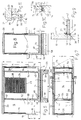
- a cuboid, non-accessible switching or small station 10 an example length a from here 3,000 mm, a width b of 1,300 mm, a total height e of approximately 2,400 mm and one above a lawn edge 12 visible height h of about 1,650 mm - to accommodate a not shown, movable on rollers transformer has on a base plate 14 molded side walls 16 and two end walls connecting them in their lower area 18 on.
- the side walls 16 carry one on their upper edges 17 attached roof panel 20.
- each of the side walls 16 there is a recess 22 for a door-like fan insert 24 is provided, the frame 26 is poured into the side wall 16 so that the outer surface the fan insert 24 within the side wall 16 runs.
- the horizontal threshold edge 23 of the recess 22 is located at a distance f of approximately 760 mm from the lower surface the bottom plate 14, the thickness i about the rest Measures 120 mm.
- the threshold edges 23 are aligned with the Top edges 19 of two concrete strips representing the end walls 18, which at a distance n of 30 mm above one of the Floor plate underside certain level E on the end walls 16 are cast on.
- the threshold edges 23 simultaneously determine the in the Grown floor lowerable base section of the switching station 10 and thus their depth of use d; the switching station 10 is embedded in the ground so that the lawn edge or soil surface 12 slightly below that Threshold edges 23 and the upper edges 19 is.
- the cross-sectionally approximately Z-shaped frame 32 is attached to the shoulder shoulder 36 with one of its legs; the other leg carries a seal 40 for the closure door 28 filled with insulating material 42 between two parallel plates 41, the front surface of which is flush with that shoulder shoulder 36.
- End wall 18 is on an edge of the rectangular base plate 14 an intermediate wall 44 formed on the other plate edge a second partition 45 is opposite.
- the Plate edges form outside these partitions 44, 45 a downwardly inclined end bead 46, the inclination of which corresponds on the inner side of the partition walls 44, 45 a counter-sloping desk surface 48 as a transition to the base plate 14. This transition is also on the side walls 16 available.
- a foundation plate 56 - the length a 1 and the width b - U-shaped cross section can be seen as a carrier for the base plate 14; the two end legs 58 of the foundation plate 56 are directed away from the base plate 14 as foot strips.
- MS partition 44 In the MS partition 44 is in its lower area slot-like opening 60 with down to the forming space 50 inclined camber 62 and also inclined bottom bench 63, which is spanned by a ventilation grille 64.
- the frame 26 for the fan insert 24 is a one Extruded frame profile made of aluminum alloy. It forms an overall U-shaped frame.
- the fan insert 24 has an insert frame 66 which with a box-like bead 68 of a front parallel Stop shoulder 70 of the side wall 16 is arranged upstream; in This edge bead 68 is supported by a hose seal in FIG. 10 40.
- a flat runs inside the insert frame 66 Sheet profile 72 of width q as a frame for cross profiles 74, each from a narrow front web 76, an inclined one Median strips and a back web 78 exist and parallel are set so that the front web 76 of one Cross section 74 of the back web 78 of the underlying Transverse profile 74 is opposite; runs between them Mesh sheet 80 as poke protection.
- Pins 82 are provided on the lower part of the sheet metal profile 72, the in a Halfen rail 84 of the recess reveal be plugged in.
- This steel bracket 88 also serves to connect the roof panel 20 and the side wall 16, as shown in FIG. 5.
- the peripheral edge 21 of the roof panel 20 is aligned with the outer surface 90 of the side wall 16, which is released upwards to form an outwardly inclined shoulder surface 92 and a joint 94 extending under the roof panel 20 so that the width y 50 mm of the remaining upper edge 17 is slightly larger than half the wall thickness i 1 .
- the width z of that joint 94 in the plane of the outer surface 90 corresponds here to the dimension of the width y 1 .
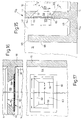
- a space cell or switching station 10 a of Fig. 12 to 17 of the ventilation slot or aperture 44 is positioned intermediate wall 60 of the total below determined by the lawn edge 12 of horizontal plane H (Fig. 14). Its lintel 62 runs - inclined downwards towards the forming space 52 - in cross-section at a greater angle of inclination w (approximately 45 °) to the horizontal than the base bank 63 - angle w 1 of 35 ° - with the lateral reveals 59 in one Horizontal angle w 2 point from here 125 ° to the forming space 50 towards one another.
- the MS intermediate wall 44 is at a distance k 1 - which here is less than half the distance k of the MS intermediate wall 44 from its adjacent end wall 18 is - a weir wall 98 upstream.
- This is molded to form an outward end bead 46 on the base plate 14 extended by a section 14 a and protrudes within the medium-voltage space 52.
- that end bead 46 with the adjacent end wall 18 delimits a bottom gap 47 of width g extending between the side walls 16 as a cable passage or the like.
- the upper edge 99 of the weir wall 98 is aligned approximately with that level H or runs slightly below this.
- the right NS partition 45 a in FIG. 12 ends slightly above level H;
- the distance f 1 of its upper edge to the lower surface of the base plate 14 is here about 800 mm and corresponds approximately to the distance f of the latter from the threshold edge 23 of the recess 22.
- this NS intermediate wall 45 a and the roof plate 20 one runs onto the NS intermediate wall 45 a attached sheet metal partition 100.
- the ventilation device in the intermediate wall 44 made of breakthrough or ventilation slot 60 and ventilation grille 64 serves for better ventilation of the transformer room 50.
- this ventilation slot 60 is inclined downwards as well as from a cross section tapering towards the forming space 50 - this to produce a Nozzle effect.
- the ventilation slot 60 shown by way of example in FIGS. 15 to 17 - with an insert frame 65 for the ventilation grille 64 molded into the intermediate wall 44 - has an external height c of 300 mm and a narrowest height c 1 of 280 mm on the transformer compartment side.
- the outer width s measures 780 mm and the narrowest inner width s 1 here 680 mm.
- the room cell 10, 10 a is cast according to FIGS. 18, 19 using a formwork core (not shown) and lateral outer switch panels 102 which can be moved to these on rollers 97, as well as frontal outer switch panels 102 a .
- the lateral outer formwork panels 102 are equipped with projecting at the lower edge of their forming surfaces 103 skirting boards 104, as well as the inside cross-sectionally part-circular curved Eckanformungen 105, also the left in Fig. 18 outer formwork panel 102 transmits neck plates 106, which has a recessed face 91 of the depth i 2 in the outer surface Generate 90 of the side wall 16.
- Those baseboards 104 rest on a formwork base 101 during the casting process and contribute to the formation of the shadow gap 94 described above.
- the recessed surfaces 91 are laterally narrow frame strips 108 limited whose surfaces in the outer surface 90 of the side wall 16 lies.
Landscapes
- Engineering & Computer Science (AREA)
- Power Engineering (AREA)
- Building Environments (AREA)
- Housings And Mounting Of Transformers (AREA)
Applications Claiming Priority (2)
| Application Number | Priority Date | Filing Date | Title |
|---|---|---|---|
| DE19648669 | 1996-11-25 | ||
| DE19648669 | 1996-11-25 |
Publications (2)
| Publication Number | Publication Date |
|---|---|
| EP0844712A2 true EP0844712A2 (fr) | 1998-05-27 |
| EP0844712A3 EP0844712A3 (fr) | 1999-05-06 |
Family
ID=7812648
Family Applications (1)
| Application Number | Title | Priority Date | Filing Date |
|---|---|---|---|
| EP97120627A Withdrawn EP0844712A3 (fr) | 1996-11-25 | 1997-11-25 | Cellule de transformation transportable et le dispositif pour sa fabrication |
Country Status (2)
| Country | Link |
|---|---|
| EP (1) | EP0844712A3 (fr) |
| DE (1) | DE19752153B4 (fr) |
Cited By (3)
| Publication number | Priority date | Publication date | Assignee | Title |
|---|---|---|---|---|
| FR2793961A1 (fr) * | 1999-05-17 | 2000-11-24 | Alstom | Poste d'exterieur prefabrique ayant un passage de cables de realimentation invisible |
| FR2972084A1 (fr) * | 2011-02-24 | 2012-08-31 | Schneider Electric Ind Sas | Poste de transformation electrique a refroidissement ameliore |
| CN103346501A (zh) * | 2013-07-22 | 2013-10-09 | 济南银河电气有限公司 | 带有报警装置的箱式变电站 |
Family Cites Families (10)
| Publication number | Priority date | Publication date | Assignee | Title |
|---|---|---|---|---|
| US3163910A (en) * | 1963-11-27 | 1965-01-05 | Tudor C Greene | Septic tank forms |
| NL6817800A (fr) * | 1968-12-11 | 1970-06-15 | ||
| DE2754843A1 (de) * | 1977-12-09 | 1979-06-13 | Hans Schwoerer Kg | Grossflaechiges fertighaus-wandelement in leichtbau-sandwich-ausfuehrung |
| DE8334221U1 (de) * | 1983-11-29 | 1984-03-01 | Betonbau GmbH, 6833 Waghäusel | Transportable umspannstation |
| DE3403889A1 (de) * | 1984-02-04 | 1985-08-08 | IBK-Ingenieurbüro Bauer + Kaletka GmbH, 7570 Baden-Baden | Verfahren und vorrichtung zum herstellen von stahlbeton-raumzellen, insbesondere fertiggaragen |
| DE59200193D1 (de) * | 1991-03-23 | 1994-07-07 | Betonbau Gmbh | Monolithische Raumzelle und Verfahren zu deren Herstellung. |
| DE4310290A1 (de) * | 1992-03-31 | 1993-10-07 | Betonbau Gmbh | Transportable Raumzelle als Umspannstation |
| JP2535140B2 (ja) * | 1994-12-06 | 1996-09-18 | 新貝工業株式会社 | コンクリ―ト製品成形用型枠装置 |
| DE19648671A1 (de) * | 1996-03-18 | 1997-09-25 | Betonbau Gmbh | Transportable Raumzelle als Umspannstation sowie Vorrichtung zu deren Herstellung |
| DE29604868U1 (de) * | 1996-03-18 | 1996-08-22 | Betonbau GmbH, 68753 Waghäusel | Transportable Raumzelle als Umspannstation |
-
1997
- 1997-11-25 EP EP97120627A patent/EP0844712A3/fr not_active Withdrawn
- 1997-11-25 DE DE19752153A patent/DE19752153B4/de not_active Expired - Lifetime
Cited By (3)
| Publication number | Priority date | Publication date | Assignee | Title |
|---|---|---|---|---|
| FR2793961A1 (fr) * | 1999-05-17 | 2000-11-24 | Alstom | Poste d'exterieur prefabrique ayant un passage de cables de realimentation invisible |
| FR2972084A1 (fr) * | 2011-02-24 | 2012-08-31 | Schneider Electric Ind Sas | Poste de transformation electrique a refroidissement ameliore |
| CN103346501A (zh) * | 2013-07-22 | 2013-10-09 | 济南银河电气有限公司 | 带有报警装置的箱式变电站 |
Also Published As
| Publication number | Publication date |
|---|---|
| DE19752153A1 (de) | 1998-07-30 |
| DE19752153B4 (de) | 2007-08-02 |
| EP0844712A3 (fr) | 1999-05-06 |
Similar Documents
| Publication | Publication Date | Title |
|---|---|---|
| EP0563436A1 (fr) | Bâtiment transportable et sa méthode de construction | |
| DE3785051T2 (de) | Methode zum errichten von trennlinien auf einem stockwerk, welches in kleinere raeume unterteilt wird, und elemente zum ausfuehren dieser methode. | |
| EP0878808A2 (fr) | Station de transformation électrique | |
| DE4020962A1 (de) | Raumzelle | |
| DE3873390T2 (de) | Entlueftung einer transformatorenstation. | |
| EP0844712A2 (fr) | Cellule de transformation transportable et le dispositif pour sa fabrication | |
| EP0768741B1 (fr) | Cellule transportable pour poste transformateur | |
| EP0209027B1 (fr) | Station de transformation transportable | |
| DE19648671A1 (de) | Transportable Raumzelle als Umspannstation sowie Vorrichtung zu deren Herstellung | |
| DE2401531A1 (de) | In das erdreich absenkbare mittelspannungsnetzstation aus betonfertigteilen in niedrigbauweise | |
| DE3409729C2 (fr) | ||
| DE19710810A1 (de) | Transportable Raumzelle als Umspannstation | |
| DE4310290A1 (de) | Transportable Raumzelle als Umspannstation | |
| AT395032B (de) | Vorgefertigtes bauelement | |
| DE10008727B4 (de) | Umspannstation | |
| DE29608752U1 (de) | Transportable Raumzelle als Umspannstation | |
| DE9214978U1 (de) | Transportable Raumzelle als Umspannstation | |
| DE2401532A1 (de) | Begehbare mittelspannungsnetzstation aus fertigteilen | |
| DE4307478A1 (en) | Switching cubicle access door with door frame - has extruded aluminium box frame with concealed hinge inside and protruding arm attached to rear of door | |
| DE10336910A1 (de) | Transformatorenstation | |
| DE19600654A1 (de) | Systemhaus | |
| DE3933588C2 (de) | Schalung zur Herstellung eines Stahlbeton-Raumkörpers variabler Abmessung | |
| DE3426831A1 (de) | Aus vorgefertigten wand- und deckentafeln bestehendes raumbausystem fuer schiffe und aehnliche baukoerper | |
| DE9002843U1 (de) | Lagervorrichtung für umweltgefährdende Stoffe | |
| DE20217746U1 (de) | Transformatorenstation |
Legal Events
| Date | Code | Title | Description |
|---|---|---|---|
| PUAI | Public reference made under article 153(3) epc to a published international application that has entered the european phase |
Free format text: ORIGINAL CODE: 0009012 |
|
| AK | Designated contracting states |
Kind code of ref document: A2 Designated state(s): AT BE CH DE DK ES FI FR GB GR IE IT LI LU MC NL PT SE |
|
| AX | Request for extension of the european patent |
Free format text: AL;LT;LV;MK;RO;SI |
|
| PUAL | Search report despatched |
Free format text: ORIGINAL CODE: 0009013 |
|
| AK | Designated contracting states |
Kind code of ref document: A3 Designated state(s): AT BE CH DE DK ES FI FR GB GR IE IT LI LU MC NL PT SE |
|
| AX | Request for extension of the european patent |
Free format text: AL;LT;LV;MK;RO;SI |
|
| AKX | Designation fees paid | ||
| REG | Reference to a national code |
Ref country code: DE Ref legal event code: 8566 |
|
| STAA | Information on the status of an ep patent application or granted ep patent |
Free format text: STATUS: THE APPLICATION IS DEEMED TO BE WITHDRAWN |
|
| 18D | Application deemed to be withdrawn |
Effective date: 19991109 |