EP0844742A2 - Méthode et dispositif pour la transmission de signaux sur l'écran de câbles à haute et moyenne tension - Google Patents
Méthode et dispositif pour la transmission de signaux sur l'écran de câbles à haute et moyenne tension Download PDFInfo
- Publication number
- EP0844742A2 EP0844742A2 EP97810816A EP97810816A EP0844742A2 EP 0844742 A2 EP0844742 A2 EP 0844742A2 EP 97810816 A EP97810816 A EP 97810816A EP 97810816 A EP97810816 A EP 97810816A EP 0844742 A2 EP0844742 A2 EP 0844742A2
- Authority
- EP
- European Patent Office
- Prior art keywords
- conductor
- signal
- inductive
- communication signals
- phase
- Prior art date
- Legal status (The legal status is an assumption and is not a legal conclusion. Google has not performed a legal analysis and makes no representation as to the accuracy of the status listed.)
- Withdrawn
Links
Images

Classifications
-
- H—ELECTRICITY
- H04—ELECTRIC COMMUNICATION TECHNIQUE
- H04B—TRANSMISSION
- H04B3/00—Line transmission systems
- H04B3/54—Systems for transmission via power distribution lines
- H04B3/56—Circuits for coupling, blocking, or by-passing of signals
-
- H—ELECTRICITY
- H02—GENERATION; CONVERSION OR DISTRIBUTION OF ELECTRIC POWER
- H02J—ELECTRIC POWER NETWORKS; CIRCUIT ARRANGEMENTS OR SYSTEMS FOR SUPPLYING OR DISTRIBUTING ELECTRIC POWER; SYSTEMS FOR STORING ELECTRIC ENERGY
- H02J13/00—Circuit arrangements for providing remote monitoring or remote control of equipment in a power distribution network
- H02J13/13—Circuit arrangements for providing remote monitoring or remote control of equipment in a power distribution network characterised by the transmission of data to equipment in the power network
- H02J13/1311—Circuit arrangements for providing remote monitoring or remote control of equipment in a power distribution network characterised by the transmission of data to equipment in the power network using the power network as support for the transmission
-
- H—ELECTRICITY
- H02—GENERATION; CONVERSION OR DISTRIBUTION OF ELECTRIC POWER
- H02J—ELECTRIC POWER NETWORKS; CIRCUIT ARRANGEMENTS OR SYSTEMS FOR SUPPLYING OR DISTRIBUTING ELECTRIC POWER; SYSTEMS FOR STORING ELECTRIC ENERGY
- H02J13/00—Circuit arrangements for providing remote monitoring or remote control of equipment in a power distribution network
- H02J13/18—Circuit arrangements for providing remote monitoring or remote control of equipment in a power distribution network characterised by the remotely-controlled equipment, e.g. converters or transformers
- H02J13/333—Circuit arrangements for providing remote monitoring or remote control of equipment in a power distribution network characterised by the remotely-controlled equipment, e.g. converters or transformers the equipment forming part of substations
-
- H—ELECTRICITY
- H04—ELECTRIC COMMUNICATION TECHNIQUE
- H04B—TRANSMISSION
- H04B2203/00—Indexing scheme relating to line transmission systems
- H04B2203/54—Aspects of powerline communications not already covered by H04B3/54 and its subgroups
- H04B2203/5404—Methods of transmitting or receiving signals via power distribution lines
- H04B2203/5416—Methods of transmitting or receiving signals via power distribution lines by adding signals to the wave form of the power source
-
- H—ELECTRICITY
- H04—ELECTRIC COMMUNICATION TECHNIQUE
- H04B—TRANSMISSION
- H04B2203/00—Indexing scheme relating to line transmission systems
- H04B2203/54—Aspects of powerline communications not already covered by H04B3/54 and its subgroups
- H04B2203/5462—Systems for power line communications
- H04B2203/5466—Systems for power line communications using three phases conductors
-
- H—ELECTRICITY
- H04—ELECTRIC COMMUNICATION TECHNIQUE
- H04B—TRANSMISSION
- H04B2203/00—Indexing scheme relating to line transmission systems
- H04B2203/54—Aspects of powerline communications not already covered by H04B3/54 and its subgroups
- H04B2203/5462—Systems for power line communications
- H04B2203/5483—Systems for power line communications using coupling circuits
-
- Y—GENERAL TAGGING OF NEW TECHNOLOGICAL DEVELOPMENTS; GENERAL TAGGING OF CROSS-SECTIONAL TECHNOLOGIES SPANNING OVER SEVERAL SECTIONS OF THE IPC; TECHNICAL SUBJECTS COVERED BY FORMER USPC CROSS-REFERENCE ART COLLECTIONS [XRACs] AND DIGESTS
- Y02—TECHNOLOGIES OR APPLICATIONS FOR MITIGATION OR ADAPTATION AGAINST CLIMATE CHANGE
- Y02E—REDUCTION OF GREENHOUSE GAS [GHG] EMISSIONS, RELATED TO ENERGY GENERATION, TRANSMISSION OR DISTRIBUTION
- Y02E60/00—Enabling technologies; Technologies with a potential or indirect contribution to GHG emissions mitigation
-
- Y—GENERAL TAGGING OF NEW TECHNOLOGICAL DEVELOPMENTS; GENERAL TAGGING OF CROSS-SECTIONAL TECHNOLOGIES SPANNING OVER SEVERAL SECTIONS OF THE IPC; TECHNICAL SUBJECTS COVERED BY FORMER USPC CROSS-REFERENCE ART COLLECTIONS [XRACs] AND DIGESTS
- Y04—INFORMATION OR COMMUNICATION TECHNOLOGIES HAVING AN IMPACT ON OTHER TECHNOLOGY AREAS
- Y04S—SYSTEMS INTEGRATING TECHNOLOGIES RELATED TO POWER NETWORK OPERATION, COMMUNICATION OR INFORMATION TECHNOLOGIES FOR IMPROVING THE ELECTRICAL POWER GENERATION, TRANSMISSION, DISTRIBUTION, MANAGEMENT OR USAGE, i.e. SMART GRIDS
- Y04S40/00—Systems for electrical power generation, transmission, distribution or end-user application management characterised by the use of communication or information technologies, or communication or information technology specific aspects supporting them
- Y04S40/12—Systems for electrical power generation, transmission, distribution or end-user application management characterised by the use of communication or information technologies, or communication or information technology specific aspects supporting them characterised by data transport means between the monitoring, controlling or managing units and monitored, controlled or operated electrical equipment
- Y04S40/121—Systems for electrical power generation, transmission, distribution or end-user application management characterised by the use of communication or information technologies, or communication or information technology specific aspects supporting them characterised by data transport means between the monitoring, controlling or managing units and monitored, controlled or operated electrical equipment using the power network as support for the transmission
Definitions
- the invention is based on a method for Signal transmission and from a signal transmission device according to the preamble of claims 1 and 4.
- German utility model G 93 15 875 U1 is one Device for feeding and receiving electrical Known signals over a medium voltage cable, in which a cable shield grounded at the end from a possibly 2-part ring core with magnetically conductive material is enclosed.
- One wound on the toroid Transmission coil is with a transmit and / or Receiving device for the electrical signals connected.
- the invention as set out in claims 1 and 4 is defined, solves the task of a method for Signal transmission and a signal transmission device of to develop in such a way that the Signal coupling is improved.
- An advantage of the invention is that the transmitting communication signals with defined, better Quality can be coupled into the signal conductor.
- existing high-frequency carrier frequencies are not automatically derived from earth potential and need thus no further active treatment by enhancers etc.
- the invention is particularly suitable for digital Signal transmission through the shielding of high and Medium voltage cables.
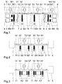
- Fig. 1 shows 2 identically structured information input and / or Decoupling stations (1, 4), which are also the same over 2 built intermediate stations (2, 3) with each other in Active connection. All 4 stations are at the same time Switch stations with switches (S1, S1 '; S2, S2'; S3, S3 '; S4, S4 ') in an electrical medium-voltage line Power cables (12) according to Fig. 4. 3 phase conductors (R, S, T) of metallically conductive phase shields or Surround signal conductors (R ', S', T ') and opposite these as well mutually electrically isolated.
- (11) is another referred to metallic conductive cable shield or signal conductor, which surrounds all 3 phase conductors (R, S, T) and to the outside is electrically insulated. It goes without saying that everyone Phase conductor (R, S, T) in a separate phase cable can have its own cable shield (11) (not shown).
- the power cable (12) is in the switch stations or Substations (1 - 4) on transformers (Tr1 - Tr4) connected by the switches (S1, S1 '; S2, S2'; S3, S3 '; S4, S4 ') can be activated.
- the Show information coupling and / or decoupling stations (1, 4) one inductive coupler (K1, K4) with one each Primary winding (W3) with at least 2 turns and 2 Secondary windings (W1, W2) with several turns.
- the two secondary windings (W1) are each with one Information transmitter (5, 9) and the two secondary windings (W2) with an information receiver (6, 10) in Active connection.
- the primary windings (W3) are on the one hand the cable shield (11) and on the other hand to earth potential connected. Parallel to each primary winding (W3) one can Surge arrester (7, 8) must be switched, so that in in the event of a fault, do not build up overvoltages and the Can reduce the protective effect of the cable shield (11).
- 1 and 2 is the cable shield (11) in the intermediate stations (2, 3) by metallic Connections (14) bridged electrically, so that a continuous connection exists.
- the cable shield (11) in each of the two Intermediate stations (2, 3) via a choke or one inductive resistor (D2, D3) connected to earth potential.
- the cable shield (11) in each of the two intermediate stations (2, 3) via two chokes or inductive resistors (D2, D2 '; D3, D3') with earth potential connected, 1 inductive resistor on each switch (S2, S2 '; S3, S3 ').
- the inductive resistors (D2, D2 '; D3, D3') represent low-pass filters, which DC and 50 Hz signals as well as their harmonic frequencies at earth potential deduce. Carrier frequencies with contained therein, too Transmitting information is not at earth potential derived so that active treatment of this Communication signals at the grounding points of the Intermediate stations (2, 3) is not required.
- the Communication signals are generated using inductive couplers (K2, K2 '; K3, K3 ') transmit their primary windings on the one hand the cable shield (11) and on the other hand to earth potential are connected.
- the secondary windings of the inductive Couplers (K2, K2 ') and (K3, K3') are each electrical connected with each other.
- These couplers (K2, K2 ') and (K3, K3'), can be constructed in the same way as the inductive couplers (K1, K4).
- FIG. 5 shows the circuit of a signal transmission device, at which the information coupling and / or decoupling station (1) corresponds to that of Fig. 1.
- the cable shield (11) is not intermediate stations (2, 3) carried out, but grounded.
- the information input and / or decoupling station (4) the input and / or Decoupling of the communication signals by means of the inductive Coupler (K4) not to the cable shield (11), but via one Capacitor (13) to at least one phase conductor (R, S, T) the power cable (12).
- the cable shield (11) is capacitive the phase conductors (R, S, T) coupled, also via the switches (S2, S3).
- inductively coupled Capacitive communication signals d. H. about the Transfer impedance of the power cable (12), are coupled out and vice versa.
- the coupling of the modulated on a carrier frequency Communication signal can be optimally based on the respective physical conditions of the point to be adapted in Adjust distribution network.
- inductive resistors D2, D2 ', D3, D3'
- inductive Couplers K2, K2 ' and (K3, K3')
- Signal transmission facilities are suitable in such places where no signal transmission via the cable shields (11) is possible.
- Signal transmission devices are particularly suitable in the urban area of buried, shielded 1- or 3-phase high and medium voltage cables.
- the cable shields (11) of these power cables (12) normally connected at the end to the general ground. No or only very small flows over the cable shields (11) Currents of 50 Hz power transmission. Only with certain In the event of a fault, the cable shields (11) must conduct currents can.
- Phase conductor shields R ', S', T ' are used as signal conductors one of them is enough.
- the primary winding (W3) of the inductive Coupler (K1, K4) an inductance of> 5 ⁇ H, preferably has an inductance in the range of 20 ⁇ H - 100 ⁇ H.
- the inductive couplers (K1, K4) do not have to be 2 Have secondary windings (W1, W2); one is sufficient Secondary winding for information transmitters (5, 9) and Information recipients (6, 10).
Landscapes
- Engineering & Computer Science (AREA)
- Power Engineering (AREA)
- Computer Networks & Wireless Communication (AREA)
- Signal Processing (AREA)
- Cable Transmission Systems, Equalization Of Radio And Reduction Of Echo (AREA)
- Near-Field Transmission Systems (AREA)
Applications Claiming Priority (2)
| Application Number | Priority Date | Filing Date | Title |
|---|---|---|---|
| DE19648382 | 1996-11-22 | ||
| DE19648382A DE19648382C1 (de) | 1996-11-22 | 1996-11-22 | Verfahren zur Signalübertragung und Signalübertragungseinrichtung |
Publications (2)
| Publication Number | Publication Date |
|---|---|
| EP0844742A2 true EP0844742A2 (fr) | 1998-05-27 |
| EP0844742A3 EP0844742A3 (fr) | 2003-09-17 |
Family
ID=7812460
Family Applications (1)
| Application Number | Title | Priority Date | Filing Date |
|---|---|---|---|
| EP97810816A Withdrawn EP0844742A3 (fr) | 1996-11-22 | 1997-10-31 | Méthode et dispositif pour la transmission de signaux sur l'écran de câbles à haute et moyenne tension |
Country Status (3)
| Country | Link |
|---|---|
| EP (1) | EP0844742A3 (fr) |
| DE (1) | DE19648382C1 (fr) |
| NO (1) | NO975333L (fr) |
Cited By (1)
| Publication number | Priority date | Publication date | Assignee | Title |
|---|---|---|---|---|
| DE10209597A1 (de) * | 2002-03-05 | 2003-09-18 | Efen Gmbh | Verfahren und Vorrichtung zur Datenübertragung über Stromversorgungsleitungen |
Families Citing this family (3)
| Publication number | Priority date | Publication date | Assignee | Title |
|---|---|---|---|---|
| DE19817575A1 (de) * | 1998-04-20 | 1999-10-21 | Abb Research Ltd | Kapazitives Koppelkabel zur Signalübertragung auf Hoch- und Mittelspannungsstromleitungen |
| DE19841864C2 (de) * | 1998-09-14 | 2000-06-29 | Abb Research Ltd | Vorrichtung zur kapazitiven Einkopplung von Kommunikationssignalen in einen Phasenleiter einer Stromleitung |
| EP2063546B1 (fr) * | 2007-11-23 | 2019-01-16 | ABB Schweiz AG | Procédé de transmission à plusieurs supports destiné à la communication de données dans des réseaux d'alimentation en courant |
Family Cites Families (2)
| Publication number | Priority date | Publication date | Assignee | Title |
|---|---|---|---|---|
| DE2615311B2 (de) * | 1976-04-06 | 1979-06-28 | Aeg-Telefunken Kabelwerke Ag, Rheydt, 4050 Moenchengladbach | Freileitungsseil mit Kommunikationskern |
| DE9315875U1 (de) * | 1993-10-18 | 1993-12-16 | Siemens AG, 80333 München | Vorrichtung zur Einkopplung bzw. zum Empfang von elektrischen Signalen in ein bzw. aus einem Energieübertragungskabel |
-
1996
- 1996-11-22 DE DE19648382A patent/DE19648382C1/de not_active Expired - Lifetime
-
1997
- 1997-10-31 EP EP97810816A patent/EP0844742A3/fr not_active Withdrawn
- 1997-11-20 NO NO975333A patent/NO975333L/no unknown
Cited By (1)
| Publication number | Priority date | Publication date | Assignee | Title |
|---|---|---|---|---|
| DE10209597A1 (de) * | 2002-03-05 | 2003-09-18 | Efen Gmbh | Verfahren und Vorrichtung zur Datenübertragung über Stromversorgungsleitungen |
Also Published As
| Publication number | Publication date |
|---|---|
| NO975333D0 (no) | 1997-11-20 |
| EP0844742A3 (fr) | 2003-09-17 |
| DE19648382C1 (de) | 1998-01-08 |
| NO975333L (no) | 1998-05-25 |
Similar Documents
| Publication | Publication Date | Title |
|---|---|---|
| DE69503496T2 (de) | Hybrides verteilungsnetzwerk zur elektrizitäts- und nachrichtenübertragung | |
| DE69329827T2 (de) | Übertragungsnetzwerk und filter hierfür | |
| WO2001008321A1 (fr) | Circuit adaptateur pour impedances caracteristiques | |
| DE3203689A1 (de) | Netzleitungs-nachrichtenverbindungssystem unter verwendung der null- und erdschutzleiter einer haushalt-zweigleitung | |
| DE102017110956A1 (de) | Vorrichtung zur Übertragung von Energie und Information über ein Ladekabel für ein Elektrofahrzeug | |
| DE2127193A1 (de) | Ankopplungseinheit zum Ankoppeln von Tragerfrequenzhochspannungsleitungen an Nachrichtengeraten oder Kabel | |
| EP1645048B1 (fr) | Circuit de couplage inductif et procede de telecommunication par des cables blindes d'un reseau electrique de distribution de courant | |
| DE2713710C2 (de) | Ferngespeister Zwischenverstärker für Nachrichtenübertragungsstrecken | |
| DE19648382C1 (de) | Verfahren zur Signalübertragung und Signalübertragungseinrichtung | |
| EP0160819B1 (fr) | Circuit de protection grossière contre la surtention pour un répéteur ou un régénérateur | |
| DE19728500C1 (de) | Datenübertragungssystem zur Übertragung von Daten über wenigstens ein elektrisches Energiekabel | |
| EP1850501A1 (fr) | Couplage adaptatif et capacitif et procédé de transmission d'informations par un câble d'alimentation blindé d'un réseau de distribution d'énergie électrique | |
| DE4319347C2 (de) | Nachrichtenübertragungsanlage für eine Krananlage | |
| DE3431537C2 (fr) | ||
| EP0014969B1 (fr) | Circuit d'entrée pour un appareil de ligne terminal du côté réception d'un système de télécommunications | |
| EP0103880B1 (fr) | Circuit d'aiguillage pour la téléalimentation d'un appareil de ligne terminal d'un système de transmission d'informations analogiques ou numériques | |
| DE4100778C1 (fr) | ||
| DE19817575A1 (de) | Kapazitives Koppelkabel zur Signalübertragung auf Hoch- und Mittelspannungsstromleitungen | |
| EP1285502A1 (fr) | Procede et dispositif pour transmettre des donnees par l'intermediaire d'un reseau de distribution electrique basse tension | |
| DE2030875C3 (de) | Schaltungsanordnung zur Herstellung einer widerstandsangepaßten netzstromsperrenden Hochfrequenzverbindung zwischen einer koaxialen Antennenleitung und dem koaxialen Eingang eines Funkgerätes | |
| DE512026C (de) | Duplexsystem fuer Nachrichtenuebermittlung mittels Hochfrequenzstroeme laengs Leitungen | |
| DE462580C (de) | Antennenanordnung zur Beeinflussung von Leitungen, insbesondere Hochspannungsleitungen und Freileitungen | |
| EP1005173A2 (fr) | Système de communication utilisant des câbles électriques de puissance blindés | |
| CH684224A5 (de) | Vorrichtung zur galvanischen Auftrennung von Koaxialkabeln. | |
| DE10209597A1 (de) | Verfahren und Vorrichtung zur Datenübertragung über Stromversorgungsleitungen |
Legal Events
| Date | Code | Title | Description |
|---|---|---|---|
| PUAI | Public reference made under article 153(3) epc to a published international application that has entered the european phase |
Free format text: ORIGINAL CODE: 0009012 |
|
| AK | Designated contracting states |
Kind code of ref document: A2 Designated state(s): AT BE CH DE DK ES FI FR GB GR IE IT LI LU MC NL PT SE |
|
| AX | Request for extension of the european patent |
Free format text: AL;LT;LV;RO;SI |
|
| PUAL | Search report despatched |
Free format text: ORIGINAL CODE: 0009013 |
|
| AK | Designated contracting states |
Kind code of ref document: A3 Designated state(s): AT BE CH DE DK ES FI FR GB GR IE IT LI LU MC NL PT SE |
|
| AX | Request for extension of the european patent |
Extension state: AL LT LV RO SI |
|
| 17P | Request for examination filed |
Effective date: 20040221 |
|
| AKX | Designation fees paid |
Designated state(s): CH DK ES FI FR GB IT LI |
|
| RBV | Designated contracting states (corrected) |
Designated state(s): AT CH ES FR GB IT LI NL |
|
| REG | Reference to a national code |
Ref country code: DE Ref legal event code: 8566 |
|
| STAA | Information on the status of an ep patent application or granted ep patent |
Free format text: STATUS: THE APPLICATION IS DEEMED TO BE WITHDRAWN |
|
| 18D | Application deemed to be withdrawn |
Effective date: 20060223 |