EP0845084B1 - Radiale aktive magnetische lagervorrichtung und verfahren zum betrieb derselben - Google Patents
Radiale aktive magnetische lagervorrichtung und verfahren zum betrieb derselben Download PDFInfo
- Publication number
- EP0845084B1 EP0845084B1 EP96926309A EP96926309A EP0845084B1 EP 0845084 B1 EP0845084 B1 EP 0845084B1 EP 96926309 A EP96926309 A EP 96926309A EP 96926309 A EP96926309 A EP 96926309A EP 0845084 B1 EP0845084 B1 EP 0845084B1
- Authority
- EP
- European Patent Office
- Prior art keywords
- electromagnets
- phase
- magnetic bearing
- coils
- accordance
- Prior art date
- Legal status (The legal status is an assumption and is not a legal conclusion. Google has not performed a legal analysis and makes no representation as to the accuracy of the status listed.)
- Expired - Lifetime
Links
Images






Classifications
-
- F—MECHANICAL ENGINEERING; LIGHTING; HEATING; WEAPONS; BLASTING
- F16—ENGINEERING ELEMENTS AND UNITS; GENERAL MEASURES FOR PRODUCING AND MAINTAINING EFFECTIVE FUNCTIONING OF MACHINES OR INSTALLATIONS; THERMAL INSULATION IN GENERAL
- F16C—SHAFTS; FLEXIBLE SHAFTS; ELEMENTS OR CRANKSHAFT MECHANISMS; ROTARY BODIES OTHER THAN GEARING ELEMENTS; BEARINGS
- F16C32/00—Bearings not otherwise provided for
- F16C32/04—Bearings not otherwise provided for using magnetic or electric supporting means
- F16C32/0406—Magnetic bearings
- F16C32/044—Active magnetic bearings
- F16C32/0459—Details of the magnetic circuit
- F16C32/0461—Details of the magnetic circuit of stationary parts of the magnetic circuit
- F16C32/0463—Details of the magnetic circuit of stationary parts of the magnetic circuit with electromagnetic bias, e.g. by extra bias windings
-
- F—MECHANICAL ENGINEERING; LIGHTING; HEATING; WEAPONS; BLASTING
- F16—ENGINEERING ELEMENTS AND UNITS; GENERAL MEASURES FOR PRODUCING AND MAINTAINING EFFECTIVE FUNCTIONING OF MACHINES OR INSTALLATIONS; THERMAL INSULATION IN GENERAL
- F16C—SHAFTS; FLEXIBLE SHAFTS; ELEMENTS OR CRANKSHAFT MECHANISMS; ROTARY BODIES OTHER THAN GEARING ELEMENTS; BEARINGS
- F16C32/00—Bearings not otherwise provided for
- F16C32/04—Bearings not otherwise provided for using magnetic or electric supporting means
- F16C32/0406—Magnetic bearings
- F16C32/044—Active magnetic bearings
- F16C32/0444—Details of devices to control the actuation of the electromagnets
- F16C32/0457—Details of the power supply to the electromagnets
-
- F—MECHANICAL ENGINEERING; LIGHTING; HEATING; WEAPONS; BLASTING
- F16—ENGINEERING ELEMENTS AND UNITS; GENERAL MEASURES FOR PRODUCING AND MAINTAINING EFFECTIVE FUNCTIONING OF MACHINES OR INSTALLATIONS; THERMAL INSULATION IN GENERAL
- F16C—SHAFTS; FLEXIBLE SHAFTS; ELEMENTS OR CRANKSHAFT MECHANISMS; ROTARY BODIES OTHER THAN GEARING ELEMENTS; BEARINGS
- F16C32/00—Bearings not otherwise provided for
- F16C32/04—Bearings not otherwise provided for using magnetic or electric supporting means
- F16C32/0406—Magnetic bearings
- F16C32/044—Active magnetic bearings
- F16C32/0474—Active magnetic bearings for rotary movement
- F16C32/0476—Active magnetic bearings for rotary movement with active support of one degree of freedom, e.g. axial magnetic bearings
-
- F—MECHANICAL ENGINEERING; LIGHTING; HEATING; WEAPONS; BLASTING
- F16—ENGINEERING ELEMENTS AND UNITS; GENERAL MEASURES FOR PRODUCING AND MAINTAINING EFFECTIVE FUNCTIONING OF MACHINES OR INSTALLATIONS; THERMAL INSULATION IN GENERAL
- F16C—SHAFTS; FLEXIBLE SHAFTS; ELEMENTS OR CRANKSHAFT MECHANISMS; ROTARY BODIES OTHER THAN GEARING ELEMENTS; BEARINGS
- F16C32/00—Bearings not otherwise provided for
- F16C32/04—Bearings not otherwise provided for using magnetic or electric supporting means
- F16C32/0406—Magnetic bearings
- F16C32/044—Active magnetic bearings
- F16C32/0474—Active magnetic bearings for rotary movement
- F16C32/048—Active magnetic bearings for rotary movement with active support of two degrees of freedom, e.g. radial magnetic bearings
-
- F—MECHANICAL ENGINEERING; LIGHTING; HEATING; WEAPONS; BLASTING
- F16—ENGINEERING ELEMENTS AND UNITS; GENERAL MEASURES FOR PRODUCING AND MAINTAINING EFFECTIVE FUNCTIONING OF MACHINES OR INSTALLATIONS; THERMAL INSULATION IN GENERAL
- F16C—SHAFTS; FLEXIBLE SHAFTS; ELEMENTS OR CRANKSHAFT MECHANISMS; ROTARY BODIES OTHER THAN GEARING ELEMENTS; BEARINGS
- F16C32/00—Bearings not otherwise provided for
- F16C32/04—Bearings not otherwise provided for using magnetic or electric supporting means
- F16C32/0406—Magnetic bearings
- F16C32/044—Active magnetic bearings
- F16C32/0474—Active magnetic bearings for rotary movement
- F16C32/0487—Active magnetic bearings for rotary movement with active support of four degrees of freedom
-
- H—ELECTRICITY
- H02—GENERATION; CONVERSION OR DISTRIBUTION OF ELECTRIC POWER
- H02K—DYNAMO-ELECTRIC MACHINES
- H02K7/00—Arrangements for handling mechanical energy structurally associated with dynamo-electric machines, e.g. structural association with mechanical driving motors or auxiliary dynamo-electric machines
- H02K7/08—Structural association with bearings
- H02K7/09—Structural association with bearings with magnetic bearings
Definitions
- EP 0 612 928 describes a radial, active one magnetic bearing for contactless storage of a rotatable body known.
- Such a magnetic Bearings include three in the circumferential direction by 120 each Electromagnets offset by degrees, each of the using three electromagnets from a separate amplifier electrical energy is supplied.
- One disadvantage of this known magnetic bearing can be seen in the fact that three separate power amplifiers are necessary that also specially designed and therefore relative are expensive.
- a Maxwell bearing is known from WO-A-90/14525, at which the stator comprises two stator rings between which a magnet to generate a bias is arranged.
- This magnet can either be a Permanent magnet or an electromagnet.
- the of this magnetizing magnetic flux is generated in axial direction over a pole piece to one Guided stator ring, there passes over the air gap between the stator ring and rotor in the radial direction in the Rotor on, and is in the axial direction along the rotor led to the other stator ring, where the Bias flow across the air gap between the rotor and stator ring in the radial direction in the others Stator ring occurs.
- Three-phase controller is a conventional, three-phase Three-phase controller or a three-phase converter is usable. These three-phase controllers are is a standard product for controlling electrical Machines, which is why such a three-phase controller very is available inexpensively.
- the active magnetic bearing according to the invention can be used as an inner rotor, i.e. with an internal rotor, or as an outrunner, i.e. with a die Electromagnet surrounding rotor, designed his.
- the active magnetic bearing requires one Premagnetization, which is caused by a permanent magnet or can be generated by a coil with a DC component is.
- Fig. 1a shows a side view Embodiment of a radial, active magnetic Camp.
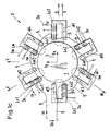
- the rotor 1 designed as a shaft is through three discreetly and U-shaped, in Circumferential direction offset by 120 ° Electromagnets 2u, 2v, 2w contactless in the balance held.
- Each electromagnet 2u, 2v, 2w has a coil Lu, Lv, Lw on to generate a time-variable, magnetic flux ⁇ 1, ⁇ 2, ⁇ 3.
- Each coil is Lu, Lv, Lw via electrical connecting lines 3u, 3v, 3w with a Three-phase controller 10, not shown, connected.
- the magnetic bearings require premagnetization, which in the present embodiment by three coils 4u, 4v, 4w through which a direct current flows becomes.
- each coil core 2u, 2v, 2w Coiled coil 4u, 4v, 4w there is one on each coil core 2u, 2v, 2w Coiled coil 4u, 4v, 4w arranged in the same direction.
- the Coils 4u, 4v, 4w are via an electrical conductor 5 connected in a series circuit and are therefore flows through a common direct current io.
- the single ones Electromagnets 2u, 2v, 2w have a direction of travel u, v, w, offset by 120 ° in the circumferential direction of the shaft 1 arranged.
- the bias current io shortens out of the Equations I to IV and is therefore in the regulation of Currents iu, iv, iw no longer to be considered.
- the bias current io is advantageously such chosen that this current io about half the Saturation flux density of the coil cores 2u, 2v, 2w generated.
- Three-phase controller 10 has a controller structure Control of the shown in Figures 1a and 1b, active magnetic bearing 6. From subordinate Meaning and therefore not shown Bias current io.
- the three coils Lu, Lv, Lw of the magnetic bearing 6 are from the power section 10a with the currents iu, iv, iw.
- Two on magnetic Bearing 6 arranged position sensors 15a, 15b detect the respective position of the rotor 1 in the X and Y directions and generate a corresponding position signal Xist, Yist, which is fed to a comparison device.
Landscapes
- Engineering & Computer Science (AREA)
- General Engineering & Computer Science (AREA)
- Mechanical Engineering (AREA)
- Physics & Mathematics (AREA)
- Electromagnetism (AREA)
- Power Engineering (AREA)
- Magnetic Bearings And Hydrostatic Bearings (AREA)
Description
- Fig. 1a
- eine Seitenansicht eines magnetischen Lagers mit drei Elektromagneten;
- Fig. 1b
- eine elektrische Schaltung mit dreiphasigem Drehstromsteller zur Ansteuerung des drei Elektromagnete umfassenden magnetischen Lagers;
- Fig. 1c
- eine Seitenansicht eines magnetischen Lagers mit sechs Elektromagneten;
- Fig. 1d
- eine elektrische Schaltung mit dreiphasigem Drehstromsteller zur Ansteuerung des sechs Elektromagnete umfassenden magnetischen Lagers;
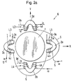
- Fig. 2a
- eine Seitenansicht eines magnetischen Lagers mit vier Elektromagneten;
- Fig. 2b
- eine elektrische Schaltung mit dreiphasigem Drehstromsteller zur Ansteuerung des vier Elektromagnete umfassenden Lagers;
- Fig. 3
- eine im Drehstromsteller angeordnete Regelvorrichtung zur Ansteuerung des magnetischen Lagers;
- Fig. 4
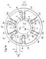
- ein weiteres Ausführungsbeispiel eines magnetischen Lagers mit vier Spulen;
- Fig. 5
- ein weiteres Ausführungsbeispiel eines magnetischen Lagers mit vier Spulen;
- Fig. 6
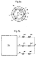
- ein magnetisches Lager mit drei als Drehstromwicklung ausgestalteten Spulen;
- Fig. 6a
- einen Querschnitt durch ein Lager gemäss Fig. 6;
- Fig. 7a
- ein weiteres Ausführungsbeispiel eines magnetischen Lagers;
- Fig. 7b
- eine elektrische Schaltung zur Ansteuerung des magnetischen Lagers gemäss Fig. 7a;
- Fig. 8a,8b
- Ausführungsbeispiele einer zusätzlich in axialer Richtung ansteuerbaren Lagervorrichtung;
- Fig. 8c
- eine elektrische Schaltung zur Ansteuerung der magnetischen Lagervorrichtung gemäss Fig. 8a.
k bedeutet in den folgenden Gleichungen eine Proportionalitätskonstante.

Claims (10)
- Radiale, aktive magnetische Maxwell-Lagervorrichtung mit einer Vormagnetisierung, umfassend zumindest drei verteilt angeordnete Elektromagnete (2a,2b,2c,2d;2u,2v,2w) und einen Leistungssteller zur Ansteuerung der Spulen (Lu,Lv,Lw; L1,L2,L3,L4) der Elektromagnete (2a,2b,2c,2d;2u,2v,2w), dadurch gekennzeichnet, dass als Leistungssteller ein dreiphasiger Drehstromsteller (10) vorgesehen ist.
- Magnetische Lagervorrichtung gemäss Anspruch 1, dadurch gekennzeichnet, dass die Elektromagnete (2a,2b,2c,2d;2u,2v,2w) diskret ausgestaltet sind.
- Magnetische Lagervorrichtung gemäss Anspruch 2, dadurch gekennzeichnet, dass drei Elektromagnete (2u,2v,2w) in einer Umfangsrichtung um 120° versetzt angeordnet sind.
- Magnetische Lagervorrichtung gemäss Anspruch 2, dadurch gekennzeichnet, dass vier Elektromagnete (2a,2b,2c,2d) in einer Umfangsrichtung um 90° versetzt angeordnet sind.
- Magnetische Lagervorrichtung gemäss Anspruch 2, dadurch gekennzeichnet, dass sechs Elektromagnete in einer Umfangsrichtung um 60° versetzt angeordnet sind.
- Magnetische Lagervorrichtung gemäss Anspruch 1, dadurch gekennzeichnet, dass die Elektromagnete (2u,2v,2w) als Drehfeldmaschinenstator mit einer Dreiphasenwicklung (Lu,Lv,Lw) ausgestaltet sind.
- Magnetische Lagervorrichtung gemäss einem der Ansprüche 1 bis 6, dadurch gekennzeichnet, dass zur Erzeugung der Vormagnetisierung zumindest eine zusätzliche Spule (4,4a,4b,4c,4d,4u,4v,4w) oder ein Permanentmagnet (40) vorgesehen ist.
- Magnetische Lagervorrichtung nach einem der Ansprüche 1 bis 7, dadurch gekennzeichnet, dass die Spulen (Lu,Lv,Lw; L1,L2,L3,L4) der Elektromagnete in einer Stern- oder Dreieckschaltung mit dem dreiphasigen Drehstromsteller (10) verbunden sind.
- Verfahren zum Betrieb einer magnetischen Maxwell-Lagervorrichtung nach einem der Ansprüche 1 bis 8, dadurch gekennzeichnet, dass die Lage des Rotors (1) in einer x- und y-Richtung durch einen Sollwert (Xsoll,Ysoll) vorgebbar ist, dass mit einem Positionssensor (15a,15b) die Lage des Rotors (1) in x- und y-Richtung erfasst wird, dass die Regelabweichung in x- und y-Richtung berechnet wird und über eine 2/3-Phasen-Transformation die Sollstromwerte (isollu, isollv) für einen dreiphasigen Drehstromsteller (10) berechnet und diesem vorgegeben werden, sodass die Spulen (Lu,Lv,Lw;L1,L2,L3,L4) der Elektromagnete (2a,2b,2c,2d;2u,2v,2w) derart mit Strom versorgt werden, dass die Lage des Rotors (1) dem vorgebbaren Sollwert (Xsoll, Ysoll) entspricht.
- Vorrichtung umfassend magnetische Maxwell-Lagervorrichtungen nach einem der Ansprüche 1 bis 8.
Priority Applications (1)
| Application Number | Priority Date | Filing Date | Title |
|---|---|---|---|
| EP96926309A EP0845084B1 (de) | 1995-08-18 | 1996-08-19 | Radiale aktive magnetische lagervorrichtung und verfahren zum betrieb derselben |
Applications Claiming Priority (7)
| Application Number | Priority Date | Filing Date | Title |
|---|---|---|---|
| CH236795 | 1995-08-18 | ||
| CH2367/95 | 1995-08-18 | ||
| CH236795 | 1995-08-18 | ||
| EP96810507 | 1996-07-30 | ||
| EP96810507 | 1996-07-30 | ||
| PCT/CH1996/000287 WO1997007341A1 (de) | 1995-08-18 | 1996-08-19 | Radiale aktive magnetische lagervorrichtung und verfahren zum betrieb derselben |
| EP96926309A EP0845084B1 (de) | 1995-08-18 | 1996-08-19 | Radiale aktive magnetische lagervorrichtung und verfahren zum betrieb derselben |
Publications (2)
| Publication Number | Publication Date |
|---|---|
| EP0845084A1 EP0845084A1 (de) | 1998-06-03 |
| EP0845084B1 true EP0845084B1 (de) | 2004-03-03 |
Family
ID=25690272
Family Applications (1)
| Application Number | Title | Priority Date | Filing Date |
|---|---|---|---|
| EP96926309A Expired - Lifetime EP0845084B1 (de) | 1995-08-18 | 1996-08-19 | Radiale aktive magnetische lagervorrichtung und verfahren zum betrieb derselben |
Country Status (4)
| Country | Link |
|---|---|
| US (1) | US6365996B2 (de) |
| EP (1) | EP0845084B1 (de) |
| DE (1) | DE59610929D1 (de) |
| WO (1) | WO1997007341A1 (de) |
Cited By (1)
| Publication number | Priority date | Publication date | Assignee | Title |
|---|---|---|---|---|
| EP2148104A1 (de) | 2008-07-21 | 2010-01-27 | Siemens Aktiengesellschaft | Magnetisches Radiallager sowie magnetisches Lagersystem mit Stromversorgung |
Families Citing this family (40)
| Publication number | Priority date | Publication date | Assignee | Title |
|---|---|---|---|---|
| DE59712591D1 (de) * | 1997-08-25 | 2006-05-04 | Levitronix Llc | Magnetgelagerte Rotationsanordnung |
| JP3636939B2 (ja) * | 1999-07-15 | 2005-04-06 | オークマ株式会社 | 磁気軸受の制御装置 |
| US6921997B2 (en) * | 2002-12-23 | 2005-07-26 | National Chung Cheng University | Active magnetic bearing with improved configuration reference cited |
| DE10353101B4 (de) * | 2003-11-12 | 2005-12-15 | Technische Universität Dresden | Verfahren zur Regelung dreiphasiger elektromagnetischer Lager |
| US20060275155A1 (en) * | 2005-01-28 | 2006-12-07 | Robert Thibodeau | Rotational apparatus |
| DE102005030724A1 (de) * | 2005-07-01 | 2007-01-04 | Levitec Gbmh | Elektrisches Magnetlagersystem |
| FR2896285B1 (fr) * | 2006-01-13 | 2008-04-18 | Mecanique Magnetique Sa Soc D | Dispositif de suspension magnetique d'un rotor |
| DE102007028229B3 (de) | 2007-06-20 | 2008-09-18 | Siemens Ag | Magnetlagersteuereinrichtung mit einem dreiphasigen Umrichter sowie Verwendung eines dreiphasigen Umrichters zur Steuerung eines Magnetlagers |
| EP2131052A1 (de) * | 2008-06-04 | 2009-12-09 | Siemens Aktiengesellschaft | Verfahren zum Lagern eines Körpers mit einer Magnetlageranordnung |
| KR101781010B1 (ko) * | 2010-09-01 | 2017-10-23 | 레비트로닉스 게엠베하 | 회전 펌프 |
| JP5577506B2 (ja) | 2010-09-14 | 2014-08-27 | ソーラテック コーポレイション | 遠心式ポンプ装置 |
| EP2693609B1 (de) | 2011-03-28 | 2017-05-03 | Thoratec Corporation | Dreh- und antriebsvorrichtung und zentrifugalpumpvorrichtung damit |
| EP2522868B1 (de) * | 2011-05-12 | 2014-03-05 | Siemens Aktiengesellschaft | Verfahren zum Betrieb eines dreiphasigen Wechselrichters eines umrichtergespeisten Magnetlagers |
| ES2495421T3 (es) * | 2011-05-20 | 2014-09-17 | Siemens Aktiengesellschaft | Cojinete radial magnético con excitación trifásica |
| DE102011077488A1 (de) * | 2011-06-14 | 2012-12-20 | Siemens Aktiengesellschaft | Magnetlager mit Drehfeld und Verfahren |
| CN104204569B (zh) * | 2012-04-04 | 2017-08-25 | 开利公司 | 多轴磁轴承和对具有主动开关拓扑的磁轴承的控制 |
| US9371826B2 (en) | 2013-01-24 | 2016-06-21 | Thoratec Corporation | Impeller position compensation using field oriented control |
| US9556873B2 (en) | 2013-02-27 | 2017-01-31 | Tc1 Llc | Startup sequence for centrifugal pump with levitated impeller |
| US10052420B2 (en) | 2013-04-30 | 2018-08-21 | Tc1 Llc | Heart beat identification and pump speed synchronization |
| US9623161B2 (en) | 2014-08-26 | 2017-04-18 | Tc1 Llc | Blood pump and method of suction detection |
| CN104696362B (zh) * | 2015-01-21 | 2017-01-11 | 北京石油化工学院 | 一种内转子径向球面纯电磁磁轴承 |
| EP4643926A3 (de) | 2015-02-11 | 2025-12-24 | Tc1 Llc | Herzschlagidentifizierung und pumpengeschwindigkeitssynchronisierung |
| US10166318B2 (en) | 2015-02-12 | 2019-01-01 | Tc1 Llc | System and method for controlling the position of a levitated rotor |
| US10371152B2 (en) | 2015-02-12 | 2019-08-06 | Tc1 Llc | Alternating pump gaps |
| US10245361B2 (en) | 2015-02-13 | 2019-04-02 | Tc1 Llc | Impeller suspension mechanism for heart pump |
| RU2589718C1 (ru) * | 2015-04-21 | 2016-07-10 | Публичное акционерное общество "Газпром автоматизация" (ПАО "Газпром автоматизация") | Система автоматического управления электромагнитным подвесом ротора |
| EP3115616B1 (de) * | 2015-07-06 | 2022-09-07 | Levitronix GmbH | Elektromagnetischer drehantrieb |
| US10177627B2 (en) | 2015-08-06 | 2019-01-08 | Massachusetts Institute Of Technology | Homopolar, flux-biased hysteresis bearingless motor |
| US10117983B2 (en) | 2015-11-16 | 2018-11-06 | Tc1 Llc | Pressure/flow characteristic modification of a centrifugal pump in a ventricular assist device |
| RU2618001C1 (ru) * | 2015-12-09 | 2017-05-05 | Федеральное государственное автономное образовательное учреждение высшего образования "Национальный исследовательский Нижегородский государственный университет им. Н.И. Лобачевского" | Способ управления работой гибкого ротора на электромагнитных подшипниках и система для его осуществления |
| US10495145B2 (en) * | 2016-04-22 | 2019-12-03 | Ingersoll-Rand Company | Active magnetic bearing controller |
| JP6407948B2 (ja) | 2016-12-21 | 2018-10-17 | ファナック株式会社 | 多相変圧器 |
| US11197990B2 (en) | 2017-01-18 | 2021-12-14 | Tc1 Llc | Systems and methods for transcutaneous power transfer using microneedles |
| WO2018182891A1 (en) * | 2017-04-01 | 2018-10-04 | Carrier Corporation | Magnetic radial bearing with flux boost |
| RU2656871C1 (ru) * | 2017-04-28 | 2018-06-07 | федеральное государственное бюджетное образовательное учреждение высшего образования "Уфимский государственный авиационный технический университет" | Способ управления положением ротора электрической машины на бесконтактных подшипниках (варианты) и электрическая машина для его реализации |
| WO2019102059A1 (en) | 2017-11-21 | 2019-05-31 | Teraloop Oy | Apparatus and method for modular stabilization of hubless rotors |
| WO2019125718A1 (en) | 2017-12-22 | 2019-06-27 | Massachusetts Institute Of Technology | Homopolar bearingless slice motors |
| US11018552B2 (en) * | 2019-04-18 | 2021-05-25 | Wisconsin Alumni Research Foundation | High-force density three pole magnetic bearing |
| WO2022032233A1 (en) * | 2020-08-07 | 2022-02-10 | Fishboat Incorporated | Robotic fish |
| CN114810826B (zh) * | 2022-03-30 | 2023-05-05 | 清华大学 | 磁轴承的零偏置控制方法、装置及磁轴承 |
Citations (1)
| Publication number | Priority date | Publication date | Assignee | Title |
|---|---|---|---|---|
| EP0612928A1 (de) * | 1993-02-22 | 1994-08-31 | Koyo Seiko Co., Ltd. | Magnetische Lagervorrichtung |
Family Cites Families (8)
| Publication number | Priority date | Publication date | Assignee | Title |
|---|---|---|---|---|
| DE2353342C2 (de) * | 1973-10-24 | 1985-08-08 | M.A.N. Maschinenfabrik Augsburg-Nürnberg AG, 8000 München | Elektromagnetische Einrichtung zum Antrieb und zur zentrierenden Lagerung von Drehkörpern |
| IE52454B1 (en) | 1980-12-24 | 1987-11-11 | Nasa | Linear magnetic bearings |
| JPS61180019A (ja) * | 1985-01-28 | 1986-08-12 | Yaskawa Electric Mfg Co Ltd | 磁気軸受 |
| JPH0198708A (ja) * | 1987-10-07 | 1989-04-17 | Ebara Res Co Ltd | ラジアル磁気軸受装置 |
| US5111102A (en) * | 1989-05-25 | 1992-05-05 | Meeks Crawford R | Magnetic bearing structure |
| US5053662A (en) * | 1990-04-18 | 1991-10-01 | General Electric Company | Electromagnetic damping of a shaft |
| US5300843A (en) * | 1992-11-02 | 1994-04-05 | General Electric Company | Fault tolerant active magnetic bearing |
| US5578880A (en) * | 1994-07-18 | 1996-11-26 | General Electric Company | Fault tolerant active magnetic bearing electric system |
-
1996
- 1996-08-19 DE DE59610929T patent/DE59610929D1/de not_active Expired - Lifetime
- 1996-08-19 WO PCT/CH1996/000287 patent/WO1997007341A1/de not_active Ceased
- 1996-08-19 EP EP96926309A patent/EP0845084B1/de not_active Expired - Lifetime
- 1996-08-19 US US09/011,604 patent/US6365996B2/en not_active Expired - Lifetime
Patent Citations (1)
| Publication number | Priority date | Publication date | Assignee | Title |
|---|---|---|---|---|
| EP0612928A1 (de) * | 1993-02-22 | 1994-08-31 | Koyo Seiko Co., Ltd. | Magnetische Lagervorrichtung |
Cited By (1)
| Publication number | Priority date | Publication date | Assignee | Title |
|---|---|---|---|---|
| EP2148104A1 (de) | 2008-07-21 | 2010-01-27 | Siemens Aktiengesellschaft | Magnetisches Radiallager sowie magnetisches Lagersystem mit Stromversorgung |
Also Published As
| Publication number | Publication date |
|---|---|
| DE59610929D1 (de) | 2004-04-08 |
| WO1997007341A1 (de) | 1997-02-27 |
| EP0845084A1 (de) | 1998-06-03 |
| US20010013733A1 (en) | 2001-08-16 |
| US6365996B2 (en) | 2002-04-02 |
Similar Documents
| Publication | Publication Date | Title |
|---|---|---|
| EP0845083B1 (de) | Magnetische lagervorrichtung und verfahren zum betrieb derselben | |
| EP0845084A1 (de) | Radiale aktive magnetische lagervorrichtung und verfahren zum betrieb derselben | |
| DE3018581C2 (de) | ||
| DE2644380C2 (de) | Werkzeugmaschinenspindellagerung, insbesondere für Schleifmaschinen | |
| DE60218935T2 (de) | Drehende elektrische Maschine mit Drehstromringspulen und Dauermagneten | |
| EP2047586B1 (de) | Synchronmotor, motorsystem, sowie verfahren zum betreiben eines motorsystems | |
| DE69409998T2 (de) | Schwingungskontrollanlage für rotierende Maschinen | |
| DE3617772A1 (de) | Elektrisches servolenksystem fuer fahrzeuge | |
| DE19726351A1 (de) | Magnetgelagerter elektrischer Antrieb mit integriertem Wicklungssystem | |
| EP2941825A2 (de) | Verfahren zum betreiben einer linearmotoranordnung und linearmotoranordnung | |
| EP0147610A2 (de) | Hohlleiterschalter | |
| DE69311088T2 (de) | Länglicher Drehmomentmotor und denselben aufweisende steuervorrichtung der winkelabweichung | |
| EP3736943A1 (de) | Drehende mehrphasen-transversalflussmaschine | |
| DE19726352A1 (de) | Magnetgelagerter elektrischer Antrieb mit konzentrierten Wicklungen | |
| EP2817526B1 (de) | Magnetische lagerung mit kraftkompensation | |
| DE112022001351T5 (de) | Treiber | |
| EP0972140B1 (de) | Verfahren und anordnung zur ansteuerung der tragwicklungs- und antriebswicklungssysteme in elektrischen maschinen mit magnetischer lagerung sowie elektrischer antrieb | |
| DE19705039A1 (de) | Mehrphasen-Gleichstrom-Elektromotor o. dgl. und Verfahren zum Starten desselben | |
| EP4067682A1 (de) | Spinnrotor-lagerung einer rotorspinnvorrichtung mit einem rotorschaft und einer lagereinheit | |
| EP0836022B1 (de) | Magnetische Lagervorrichtung und Verfahren zum Betrieb derselben | |
| EP0989315B1 (de) | Magnetische Lagervorrichtung | |
| EP0739457B1 (de) | Verfahren und steuergerät zur steuerung einer elektrischen drehfeldmaschine mit spezialwicklung zur kombinierten erzeugung eines drehmoments und einer querkraft in derselben | |
| EP1158648B1 (de) | Elektromagnetischer Drehantrieb | |
| DE3004752A1 (de) | Elektrischer generator | |
| DE102022113082A1 (de) | Antriebseinheit für einen Spinnrotor einer Rotorspinnvorrichtung |
Legal Events
| Date | Code | Title | Description |
|---|---|---|---|
| PUAI | Public reference made under article 153(3) epc to a published international application that has entered the european phase |
Free format text: ORIGINAL CODE: 0009012 |
|
| 17P | Request for examination filed |
Effective date: 19971023 |
|
| AK | Designated contracting states |
Kind code of ref document: A1 Designated state(s): CH DE FR GB LI |
|
| 17Q | First examination report despatched |
Effective date: 19981029 |
|
| RAP1 | Party data changed (applicant data changed or rights of an application transferred) |
Owner name: LUST ANTRIEBSTECHNIK GMBH |
|
| GRAP | Despatch of communication of intention to grant a patent |
Free format text: ORIGINAL CODE: EPIDOSNIGR1 |
|
| GRAS | Grant fee paid |
Free format text: ORIGINAL CODE: EPIDOSNIGR3 |
|
| GRAA | (expected) grant |
Free format text: ORIGINAL CODE: 0009210 |
|
| AK | Designated contracting states |
Kind code of ref document: B1 Designated state(s): CH DE FR GB LI |
|
| REG | Reference to a national code |
Ref country code: GB Ref legal event code: FG4D Free format text: NOT ENGLISH |
|
| REG | Reference to a national code |
Ref country code: CH Ref legal event code: EP |
|
| GBT | Gb: translation of ep patent filed (gb section 77(6)(a)/1977) |
Effective date: 20040303 |
|
| REG | Reference to a national code |
Ref country code: CH Ref legal event code: NV Representative=s name: SULZER MANAGEMENT AG PATENTABTEILUNG Ref country code: CH Ref legal event code: EP |
|
| REF | Corresponds to: |
Ref document number: 59610929 Country of ref document: DE Date of ref document: 20040408 Kind code of ref document: P |
|
| ET | Fr: translation filed | ||
| PLBE | No opposition filed within time limit |
Free format text: ORIGINAL CODE: 0009261 |
|
| STAA | Information on the status of an ep patent application or granted ep patent |
Free format text: STATUS: NO OPPOSITION FILED WITHIN TIME LIMIT |
|
| 26N | No opposition filed |
Effective date: 20041206 |
|
| REG | Reference to a national code |
Ref country code: CH Ref legal event code: PFA Owner name: LTI DRIVES GMBH, DE Free format text: FORMER OWNER: LUST ANTRIEBSTECHNIK GMBH, DE Ref country code: CH Ref legal event code: NV Representative=s name: INTELLECTUAL PROPERTY SERVICES GMBH, CH |
|
| REG | Reference to a national code |
Ref country code: CH Ref legal event code: PCAR Free format text: NEW ADDRESS: LANGFELDSTRASSE 88, 8500 FRAUENFELD (CH) |
|
| REG | Reference to a national code |
Ref country code: FR Ref legal event code: PLFP Year of fee payment: 20 |
|
| PGFP | Annual fee paid to national office [announced via postgrant information from national office to epo] |
Ref country code: DE Payment date: 20150821 Year of fee payment: 20 Ref country code: GB Payment date: 20150819 Year of fee payment: 20 Ref country code: CH Payment date: 20150819 Year of fee payment: 20 |
|
| PGFP | Annual fee paid to national office [announced via postgrant information from national office to epo] |
Ref country code: FR Payment date: 20150820 Year of fee payment: 20 |
|
| REG | Reference to a national code |
Ref country code: DE Ref legal event code: R071 Ref document number: 59610929 Country of ref document: DE |
|
| REG | Reference to a national code |
Ref country code: CH Ref legal event code: PL |
|
| REG | Reference to a national code |
Ref country code: GB Ref legal event code: PE20 Expiry date: 20160818 |
|
| PG25 | Lapsed in a contracting state [announced via postgrant information from national office to epo] |
Ref country code: GB Free format text: LAPSE BECAUSE OF EXPIRATION OF PROTECTION Effective date: 20160818 |