EP0845196B1 - Galette pour chauffer un fil synthetique continu - Google Patents
Galette pour chauffer un fil synthetique continu Download PDFInfo
- Publication number
- EP0845196B1 EP0845196B1 EP97928210A EP97928210A EP0845196B1 EP 0845196 B1 EP0845196 B1 EP 0845196B1 EP 97928210 A EP97928210 A EP 97928210A EP 97928210 A EP97928210 A EP 97928210A EP 0845196 B1 EP0845196 B1 EP 0845196B1
- Authority
- EP
- European Patent Office
- Prior art keywords
- godet
- carrier
- coil support
- transformer sheets
- primary windings
- Prior art date
- Legal status (The legal status is an assumption and is not a legal conclusion. Google has not performed a legal analysis and makes no representation as to the accuracy of the status listed.)
- Expired - Lifetime
Links
- 238000010438 heat treatment Methods 0.000 title claims description 6
- 238000004804 winding Methods 0.000 claims description 22
- 239000000969 carrier Substances 0.000 claims description 9
- 230000004907 flux Effects 0.000 description 12
- 230000005611 electricity Effects 0.000 description 4
- 230000007423 decrease Effects 0.000 description 2
- 230000035515 penetration Effects 0.000 description 2
- 238000010276 construction Methods 0.000 description 1
- 230000001419 dependent effect Effects 0.000 description 1
- 238000011161 development Methods 0.000 description 1
- 230000018109 developmental process Effects 0.000 description 1
- 230000000694 effects Effects 0.000 description 1
- 150000002505 iron Chemical class 0.000 description 1
- 238000004519 manufacturing process Methods 0.000 description 1
- 239000000463 material Substances 0.000 description 1
Images

Classifications
-
- H—ELECTRICITY
- H05—ELECTRIC TECHNIQUES NOT OTHERWISE PROVIDED FOR
- H05B—ELECTRIC HEATING; ELECTRIC LIGHT SOURCES NOT OTHERWISE PROVIDED FOR; CIRCUIT ARRANGEMENTS FOR ELECTRIC LIGHT SOURCES, IN GENERAL
- H05B6/00—Heating by electric, magnetic or electromagnetic fields
- H05B6/02—Induction heating
- H05B6/10—Induction heating apparatus, other than furnaces, for specific applications
- H05B6/14—Tools, e.g. nozzles, rollers, calenders
- H05B6/145—Heated rollers
-
- D—TEXTILES; PAPER
- D02—YARNS; MECHANICAL FINISHING OF YARNS OR ROPES; WARPING OR BEAMING
- D02J—FINISHING OR DRESSING OF FILAMENTS, YARNS, THREADS, CORDS, ROPES OR THE LIKE
- D02J13/00—Heating or cooling the yarn, thread, cord, rope, or the like, not specific to any one of the processes provided for in this subclass
- D02J13/005—Heating or cooling the yarn, thread, cord, rope, or the like, not specific to any one of the processes provided for in this subclass by contact with at least one rotating roll
Definitions
- the invention relates to a godet for heating a running synthetic Thread according to the preamble of claim 1.
- Such godets are known.
- US 3,508,024 is a godet for Heating a running thread is described which is more than two axially successively arranged stationary primary windings and one magnetically conductive godet sheath, which is concentric with the primary windings is rotatably mounted and which with the primary windings a narrow radial gap inductively connected to generate secondary currents is.
- the carrier of the primary windings is made of several layers Transformer sheets built up perpendicular to the axis of the coil carrier are attached.
- the primary windings are activated by means of a respective control circuit operated with an AC adjustable frequency, wherein the primary windings are enclosed in a resonant circuit, which on the set frequency is tuned. Via appropriate circuit breakers the resonant circuit is in cooperation with assigned temperature controllers depending on the measured temperature at the godet jacket or can be switched off.
- a similar godet is described in GB 989,349, in which one Primary winding on a concentric in a hollow cylindrical godet jacket arranged round beam is attached.
- the laminated iron sheets are arranged so that ring-shaped, radial concentric air gaps are formed to the godet axis of rotation.
- Another advantage is that commercially available cutting tape cores for Recording the windings can be used. That simplifies the Manufacturing process and reduces costs.
- the one between neighboring The gap forming the cutting tape cores leads to a very small stray field, that has no influence on the electricity generated and thus the temperature in the Has a godet.
- the surface shape of the groove base over which the carrier on the Coil carrier is arranged simplifies assembly.
- Thin transformer sheets required for high-frequency use can also be used up to a thickness of 0.01 mm can be used. Because the depth of penetration of the magnetic flux decreases with increasing frequency and the conduction of the magnetic flux, however, only on the surface takes place, such thin sheets are appropriate to the power loss to keep as low as possible.
- FIG. 1 In the case of an inductively heated godet shown in FIG. 1, several are axial Carrier 3 located on a coil carrier 5, each with a primary winding 1 provided.
- a godet casing 2 by means of a cone arrangement 7 clamped on a spindle 9 mounted in two bearings 8.
- the bearings 8 are supported on a fixed receiving body 11.
- the godet casing 2 is essentially U-shaped in cross section and has a central opening on its end wall 2a, which is from an im substantially cylindrical inward projection 13 is limited which has an inner cone 7 which is a cone of the spindle 9 fits.
- There is a thread on the free end of the spindle 9 which a nut 10 to fix the godet 2 on the Spindle 9 is attachable.
- From the receiving body 11 extends in Shape of a hollow cylinder a coil carrier 5 over the spindle 9 almost to End wall 2a of the godet casing 2.
- On the coil carrier 5 are in axial Direction of several carriers 3 one behind the other on the circumference of the coil carrier 5 arranged.
- the carriers 3 each have a groove base 3a and at a distance mutually arranged legs 3b, so that a U-shaped annular space is formed, which serves to receive the primary winding 1.
- the Legs 3b extend to just before the inner surface of the godet casing 2.
- Two adjacent legs 3b form with this inner lateral surface each have a defined radial gap 4 corresponding to the leg width Dimension.
- a corresponding control device (not shown) is used in the Carriers 3 arranged primary windings 1 separately controllable, so that a substantially constant temperature along the outer surface of the Godet casing 2 can be achieved.
- the rotating godet jacket 2 Via the annular gap 4 between the legs 3b and the inner surface of the godet casing 2, which is magnetic is conductive, the rotating godet jacket 2 is magnetically coupled, so that a voltage is induced in the godet jacket that one Current flow.
- the current flow in the godet jacket along the circumference has, due to the electrical resistance of the godet material, heating.
- By switching the coil voltage on and off the temperature in the godet jacket can be adjusted.
- To loss of performance especially when using high-frequency, for example 2 kHz and above are the transformer plates in the Groove base arranged so that they lie radially one above the other.
- FIG. 2 shows a locally enlarged sectional view of the groove base 3a, in which the transformer plates radially one above the other in the area of the groove base are stacked.
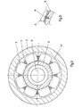
- the carrier 3 and 5 show a preferred exemplary embodiment, after the carrier 3 are formed so that the layered transformer sheets Are stacked in a U-shape into so-called cutting tape cores, i.e. the transformer plates are in the radial direction and not - as is generally known - Layered in the axial direction.
- the bobbin 5 On the circumference of the bobbin 5 are a plurality of U-shaped slit band cores 3 arranged in segments to form a plurality. The on the circumference of the bobbin in the circumferential direction without clearance mutually arranged segment-shaped cutting tape cores 3 thus form a winding support for a primary winding.
- the advantage of using of cut tape cores 3 is that the magnetic flux to the outside towards, in particular also towards the coil carrier 5, is shielded so that none Stray field can step out.
- the layered transformer sheets are used for this Stacked in a U-shape. This also creates an optimal magnetic flux enabled that does not have to cross any boundary layers.
- transformer sheets which are arranged one behind the other in the axial direction are at high-frequency application with, for example, 2 kHz thicker boundary layers causes, which lead to a considerable increase in resistance.
- the Surface of the groove base 3a, on which the step belt core 3 on the carrier 5 is either substantially flat or the surface of the Carrier 5 adapted and touches the surface of the carrier 5. The winding takes place in the circumferential direction.
- the free ends of the legs 3b of the cutting tape cores are rounded so that there is between the godet 2 and the free end of the legs 3b a substantially constant Radial gap 4 forms.
- the between adjacent cutting core 3 Forming gap 14 leads to a very small stray field that none Influence on the electricity generated and thus the temperature in the godet jacket 2 has.
- the core of the adjacent primary windings can be cut in this way offset from each other that axially around the width of the Form leg 3b delimited column 14.
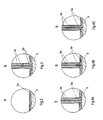
- the groove base 3a of the carrier 3 is a hollow cylinder made of several transformer sheets stacked in the radial direction.
- the legs 3b of the wearer 3 have a plurality of axially stacked annular transformer plates. The between The radial stray field guided in the groove base 3a and the legs 3b is very large low, which is why no influence on the generated electricity and thus on the Temperature in the godet jacket 2 is present.
- FIG. 4B Another preferred exemplary embodiment is shown in FIG. 4B, in which the carrier 3 from separate legs 3b and a separate Groove base 3a exists.
- the groove base 3a of the carrier 3 is a hollow cylinder from several transformer sheets stacked in the radial direction.
- the legs 3b of the cutting tape core 3 have a plurality of stacked annular transformer sheets on.
- the axial between the groove base 3a and the legs 3b Stray field is very small, which has no effect on the electricity generated and so that it has the temperature in the godet casing 2.
- FIG. 4C Another preferred exemplary embodiment is shown in FIG. 4C, in which the carrier 3 from separate legs 3b and a separate Groove base 3a exists.
- the groove base 3a of the cutting tape core 3 is a Hollow cylinder made of several transformer sheets stacked in the radial direction.
- the Legs 3b of the carrier 3 have a plurality of stacked annular transformer sheets on. That guided between the groove base 3a and the legs 3b oblique stray field is very small, which is why no influence on the generated Current and thus the temperature in the godet jacket 2 is present.
- a shape of the leg 3b is shown, both with the The arrangement in FIG. 4A and also the arrangement in FIG. 4B can be combined is.
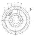
- the leg 3b is stacked from a plurality of annular transformer sheets. This arrangement is particularly low loss, since the radial gap 4 between the leg 3b and the godet casing 2 all the way around is carried out essentially constant. The stray magnetic flux is very low.
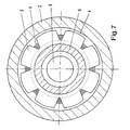
- FIG. 7 another form of the leg 3b is shown, both with the arrangement in FIG. 4A as well as the arrangement in FIG. 4B can be combined in which each ring-shaped transformer sheet is a star-shaped one Has outer edge.
- the transformer plates are stacked axially so that the star-shaped ones Outer edges are aligned axially one after the other.
- Fig. 8 is a possible attachment of the carrier 3 on the coil carrier 5, in which, for example, the cutting band cores are formed Carrier 3 each with at least one screw 6 on the coil carrier 5 the godet 2 are attached.
- U-shaped layered transformer sheets in particular Cut tape cores also have the advantage that those for high-frequency Application required thin sheets up to 0.01 mm can be. Since the depth of penetration of the magnetic flux with increasing frequency decreases and the power of the magnetic flux but only on the surface. are such thin sheets required in order to keep the power losses lower.
Landscapes
- Physics & Mathematics (AREA)
- Electromagnetism (AREA)
- Engineering & Computer Science (AREA)
- Textile Engineering (AREA)
- General Induction Heating (AREA)
- Resistance Heating (AREA)
- Yarns And Mechanical Finishing Of Yarns Or Ropes (AREA)
Claims (12)
- Galet pour chauffer un fil synthétique en mouvement qui présente une pluralité d'enroulements primaires stationnaires (1) et une enveloppe de galet (2) à conduction magnétique étant montée avec possibilité de rotation par rapport à ceux-ci, lesquels enroulements primaires (1) étant respectivement enroulés sur au moins un support en forme de U (3) qui est constitué de plusieurs tôles de transformateur, les supports en forme de U étant agencés par rapport à l'enveloppe de galet (2) sur un support de bobine (5) concentriquement l'un derrière l'autre et l'enveloppe de galet (2) étant couplée à l'intermédiaire des branches (3b) du support (3) aux enroulements primaires (1) respectivement par une fente radiale définie (4) afin de générer des courants induits, dans quel cas le support (3) est réalisé de telle manière que dans la zone de fond de rainure (3a) ses tôles de transformateur sont radialement superposées et sont agencées de telle manière qu'elles sont orientées en direction axiale du support de bobine (5) et que dans la zone des branches (3b) ses tôles de transformateur sont disposées de manière axiale l'une derrière l'autre et sont agencées de telle manière qu'elles sont orientées en direction radiale du support de bobine (5), caractérisé en ce que le support (3) présente plusieurs tôles de transformateur empilées en forme de U l'une dans l'autre en tant que tore enroulé fendu.
- Galet selon la revendication 1, caractérisé en ce que le support (3) présente des branches (3b) séparées et un fond de rainure (3a) séparé.
- Galet selon la revendication 2, caractérisé en ce que le fond de rainure séparé (3a) présente un cylindre creux étant constitué de plusieurs tôles de transformateur empilées en direction radiale.
- Galet selon la revendication 2, caractérisé en ce que chaque branche (3b) séparée présente plusieurs tôles de transformateur annulaires empilées de manière axiale.
- Galet selon la revendication 2, caractérisé en ce que chaque branche séparée (3b) présente plusieurs tôles de transformateur en forme d'étoiles, les tôles de transformateur étant empilées de manière axiale.
- Galet selon la revendication 1, caractérisé en ce qu'une pluralité des supports (3) est agencée en forme de segments sur la périphérie du support de bobine (5) pour recevoir un des enroulements primaires (1).
- Galet selon la revendication 6, caractérisé en ce que le fond de rainure (3a) des supports (3) en forme de segments est sensiblement plane et touche la surface du support de bobine (5).
- Galet selon la revendication 6 ou 7, caractérisé en ce que sur leurs extrémités libres les branches (3b) des supports en forme de segments (3) sont réalisés de telle manière en forme d'arc qu'une fente radiale (4) s'ajuste entre le support (3) et l'enveloppe de galette (2) qui est sensiblement constante.
- Galet selon la revendication 6, caractérisé en ce que la surface extérieure du fond de rainure (3a) au-dessus de laquelle le support est agencé sur le support de bobine (5) est adaptée à la surface du support de bobine (5).
- Galet selon l'une des revendications 6 à 9, caractérisé en ce que les supports en forme de segments (3) d'enroulements primaires (1) adjacents sont agencés de manière décalée l'un à l'autre sur la périphérie du support de bobine (5) en direction axiale du support de bobine (5).
- Galet selon l'une des revendications 1 à 10, caractérisé en ce que les supports (3) sont respectivement fixés au moyen d'au moins une vis (6) sur le support de bobine (5) du galet.
- Galet selon l'une des revendications 1 à 11, caractérisé en ce que les tôles de transformateur ont une épaisseur jusqu'à 0,01 mm.
Applications Claiming Priority (3)
| Application Number | Priority Date | Filing Date | Title |
|---|---|---|---|
| DE19624266 | 1996-06-18 | ||
| DE19624266 | 1996-06-18 | ||
| PCT/EP1997/003121 WO1997049265A1 (fr) | 1996-06-18 | 1997-06-16 | Galette pour chauffer un fil synthetique continu |
Publications (3)
| Publication Number | Publication Date |
|---|---|
| EP0845196A1 EP0845196A1 (fr) | 1998-06-03 |
| EP0845196B1 true EP0845196B1 (fr) | 2002-11-27 |
| EP0845196B2 EP0845196B2 (fr) | 2011-07-06 |
Family
ID=7797255
Family Applications (1)
| Application Number | Title | Priority Date | Filing Date |
|---|---|---|---|
| EP97928210A Expired - Lifetime EP0845196B2 (fr) | 1996-06-18 | 1997-06-16 | Galette pour chauffer un fil synthetique continu |
Country Status (7)
| Country | Link |
|---|---|
| US (1) | US5970592A (fr) |
| EP (1) | EP0845196B2 (fr) |
| KR (1) | KR100446346B1 (fr) |
| CN (1) | CN1135908C (fr) |
| DE (1) | DE59708815D1 (fr) |
| TW (1) | TW354339B (fr) |
| WO (1) | WO1997049265A1 (fr) |
Cited By (1)
| Publication number | Priority date | Publication date | Assignee | Title |
|---|---|---|---|---|
| EP1614783A1 (fr) * | 2004-07-06 | 2006-01-11 | Schärer Schweiter Mettler AG | noyau d'inductance pour une galette à chauffer |
Families Citing this family (6)
| Publication number | Priority date | Publication date | Assignee | Title |
|---|---|---|---|---|
| US7105784B2 (en) * | 2003-03-24 | 2006-09-12 | Kabushiki Kaisha Toshiba | Fixing device |
| US6861627B2 (en) * | 2003-03-26 | 2005-03-01 | Kabushiki Kaisha Toshiba | Induction heat fixing device |
| CN102560798A (zh) * | 2004-10-14 | 2012-07-11 | 苏拉有限及两合公司 | 用于引导、加热和输送长丝的导丝辊 |
| US7317177B2 (en) * | 2006-04-24 | 2008-01-08 | Inductoheat, Inc. | Electric induction heat treatment of an end of tubular material |
| CN101431884B (zh) * | 2008-12-11 | 2013-03-20 | 马嘉惠 | 一种与射频聚焦加热装置配套的电磁屏蔽装置 |
| CN115198419B (zh) * | 2022-08-12 | 2023-09-26 | 昆山联滔电子有限公司 | 一种编织线热压机 |
Family Cites Families (18)
| Publication number | Priority date | Publication date | Assignee | Title |
|---|---|---|---|---|
| GB858855A (en) * | 1956-05-15 | 1961-01-18 | Wild Barfield Electr Furnaces | Induction heated rotary rollers |
| NL283604A (fr) * | 1961-09-26 | 1900-01-01 | ||
| GB1121860A (en) * | 1964-11-21 | 1968-07-31 | Tokushu Denki Kabushiki Kaisha | A heating rotary drum apparatus |
| BE716725A (fr) * | 1965-12-03 | 1968-12-02 | ||
| US3412229A (en) * | 1966-10-20 | 1968-11-19 | Cameron Brown Capital Corp | Electric heating means |
| RO55797A (fr) * | 1967-08-16 | 1974-01-03 | ||
| DE1660235C3 (de) * | 1967-08-16 | 1980-06-26 | Barmag Barmer Maschinenfabrik Ag, 5600 Wuppertal | Induktiv beheizbare Galette |
| US3448233A (en) * | 1967-09-26 | 1969-06-03 | Pillar Corp | Induction heating assembly |
| US3508024A (en) * | 1968-06-17 | 1970-04-21 | Gen Electric | Dual inductance induction heater |
| BE736709A (fr) * | 1968-10-24 | 1969-12-31 | ||
| US3562472A (en) † | 1969-08-20 | 1971-02-09 | Gen Electric | Induction heater for rotating godet |
| GB1319318A (en) * | 1970-07-01 | 1973-06-06 | Platt International Ltd | Inductively heatable roller having a temperature sensor |
| JPS6139394A (ja) * | 1984-07-30 | 1986-02-25 | トクデン株式会社 | 3相環状成層鉄心脚型回転ロ−ラ |
| EP0349829B1 (fr) * | 1988-06-30 | 1996-04-17 | Maschinenfabrik Rieter Ag | Galette à large champ de vitesse de rotation |
| US5159166A (en) * | 1988-06-30 | 1992-10-27 | Rieter Machine Works, Ltd. | Drawroll unit |
| DE59202786D1 (de) * | 1991-04-27 | 1995-08-10 | Barmag Barmer Maschf | Galette zum Erhitzen eines laufenden Fadens. |
| DE4339903A1 (de) * | 1992-12-03 | 1994-06-09 | Barmag Barmer Maschf | Galette zur Führung und Förderung eines Fadens |
| CH690599A5 (de) * | 1994-11-10 | 2000-10-31 | Barmag Barmer Maschf | Galetteneinheit zum Heizen und Fördern von Fäden. |
-
1997
- 1997-06-16 US US09/011,848 patent/US5970592A/en not_active Expired - Fee Related
- 1997-06-16 KR KR10-1998-0700959A patent/KR100446346B1/ko not_active Expired - Fee Related
- 1997-06-16 DE DE59708815T patent/DE59708815D1/de not_active Expired - Lifetime
- 1997-06-16 WO PCT/EP1997/003121 patent/WO1997049265A1/fr not_active Ceased
- 1997-06-16 EP EP97928210A patent/EP0845196B2/fr not_active Expired - Lifetime
- 1997-06-16 CN CNB971907315A patent/CN1135908C/zh not_active Expired - Fee Related
- 1997-06-18 TW TW086108517A patent/TW354339B/zh not_active IP Right Cessation
Cited By (2)
| Publication number | Priority date | Publication date | Assignee | Title |
|---|---|---|---|---|
| EP1614783A1 (fr) * | 2004-07-06 | 2006-01-11 | Schärer Schweiter Mettler AG | noyau d'inductance pour une galette à chauffer |
| US7170386B2 (en) | 2004-07-06 | 2007-01-30 | Schärer Schweiter Mettler Ag | Inductor core for heatable godet roll |
Also Published As
| Publication number | Publication date |
|---|---|
| CN1135908C (zh) | 2004-01-21 |
| TW354339B (en) | 1999-03-11 |
| EP0845196B2 (fr) | 2011-07-06 |
| DE59708815D1 (de) | 2003-01-09 |
| WO1997049265A1 (fr) | 1997-12-24 |
| EP0845196A1 (fr) | 1998-06-03 |
| KR19990036291A (ko) | 1999-05-25 |
| US5970592A (en) | 1999-10-26 |
| KR100446346B1 (ko) | 2004-10-14 |
| CN1196864A (zh) | 1998-10-21 |
Similar Documents
| Publication | Publication Date | Title |
|---|---|---|
| DE68919640T2 (de) | Hochfrequenzheizgerät mit einer frequenzumwandelnden Speisung. | |
| EP0104384A1 (fr) | Dispositif de contact d'un interrupteur à vide | |
| DE69216506T2 (de) | Oberwellenfilterreaktor hoher Verlustleistung | |
| EP0845196B1 (fr) | Galette pour chauffer un fil synthetique continu | |
| DE3900684A1 (de) | Schaltkontakt fuer vakuumschalter | |
| DE4124264C2 (de) | Motorischer Schweißautomat | |
| DE3527271A1 (de) | Drehbare walze mit dreiphasigem, in umfangsrichtung lamelliertem stegkern | |
| EP1725420B1 (fr) | Ensemble magnetique pour des systemes de portee, de guidage et/ou de freinage dans des vehicules a sustentation magnetique | |
| DE1660235A1 (de) | Induktiv beheizbare Galette | |
| DE3212197A1 (de) | Laeufer fuer eine supraleitende elektrische rotationsmaschine | |
| EP0511549B1 (fr) | Rouleau pour chauffer un fil en mouvement | |
| WO2025036530A1 (fr) | Machine électrique, en particulier machine à flux axial, dotée d'une structure de blindage | |
| CA1078476A (fr) | Blindage electrostatique a spires partielles ameliorant la distribution des impulsions de tension pour enroulements en disque. | |
| DE1242265B (de) | Leistungskryotron | |
| DE2533385C2 (de) | Vorrichtung zur Steuerung der Impedanz eines Induktionsmotors | |
| WO2002095104A1 (fr) | Galette | |
| WO1988006783A1 (fr) | Appareil d'enregistrement sur bandes magnetiques avec un dispositif de transmission sans contact de signaux entre des composants mobiles les uns par rapport aux autres | |
| EP0167896B1 (fr) | Bobinage de bobine à plateaux pour transformateurs | |
| EP0053686B1 (fr) | Réactance à noyau plongeur | |
| DE102004011941A1 (de) | Magnetpol für Magnetschwebefahrzeuge | |
| EP0154697B1 (fr) | Enroulement à haute tension avec distribution du potentiel contraint pour transformateurs | |
| WO2005087532A1 (fr) | Pole magnetique de vehicules a sustentation magnetique | |
| DE3326422C2 (fr) | ||
| EP3977493B1 (fr) | Composant inductif et procédé de réglage d'une inductance | |
| DE29820958U1 (de) | Induktionsheizung für Thermowalzen |
Legal Events
| Date | Code | Title | Description |
|---|---|---|---|
| PUAI | Public reference made under article 153(3) epc to a published international application that has entered the european phase |
Free format text: ORIGINAL CODE: 0009012 |
|
| 17P | Request for examination filed |
Effective date: 19980219 |
|
| AK | Designated contracting states |
Kind code of ref document: A1 Designated state(s): CH DE FR LI |
|
| 17Q | First examination report despatched |
Effective date: 20020129 |
|
| GRAG | Despatch of communication of intention to grant |
Free format text: ORIGINAL CODE: EPIDOS AGRA |
|
| GRAG | Despatch of communication of intention to grant |
Free format text: ORIGINAL CODE: EPIDOS AGRA |
|
| GRAH | Despatch of communication of intention to grant a patent |
Free format text: ORIGINAL CODE: EPIDOS IGRA |
|
| GRAH | Despatch of communication of intention to grant a patent |
Free format text: ORIGINAL CODE: EPIDOS IGRA |
|
| GRAA | (expected) grant |
Free format text: ORIGINAL CODE: 0009210 |
|
| AK | Designated contracting states |
Kind code of ref document: B1 Designated state(s): CH DE FR LI |
|
| REG | Reference to a national code |
Ref country code: CH Ref legal event code: EP |
|
| REF | Corresponds to: |
Ref document number: 59708815 Country of ref document: DE Date of ref document: 20030109 |
|
| REG | Reference to a national code |
Ref country code: CH Ref legal event code: NV Representative=s name: HERMANN KAHLHOEFER |
|
| ET | Fr: translation filed | ||
| PLBQ | Unpublished change to opponent data |
Free format text: ORIGINAL CODE: EPIDOS OPPO |
|
| PLBI | Opposition filed |
Free format text: ORIGINAL CODE: 0009260 |
|
| PLAX | Notice of opposition and request to file observation + time limit sent |
Free format text: ORIGINAL CODE: EPIDOSNOBS2 |
|
| 26 | Opposition filed |
Opponent name: DIENES APPARATEBAU GMBH Effective date: 20030819 |
|
| PLBB | Reply of patent proprietor to notice(s) of opposition received |
Free format text: ORIGINAL CODE: EPIDOSNOBS3 |
|
| RAP2 | Party data changed (patent owner data changed or rights of a patent transferred) |
Owner name: SAURER GMBH & CO. KG |
|
| PLAB | Opposition data, opponent's data or that of the opponent's representative modified |
Free format text: ORIGINAL CODE: 0009299OPPO |
|
| RAP2 | Party data changed (patent owner data changed or rights of a patent transferred) |
Owner name: OERLIKON TEXTILE GMBH & CO. KG |
|
| APBP | Date of receipt of notice of appeal recorded |
Free format text: ORIGINAL CODE: EPIDOSNNOA2O |
|
| APAH | Appeal reference modified |
Free format text: ORIGINAL CODE: EPIDOSCREFNO |
|
| APAY | Date of receipt of notice of appeal deleted |
Free format text: ORIGINAL CODE: EPIDOSDNOA2O |
|
| APBM | Appeal reference recorded |
Free format text: ORIGINAL CODE: EPIDOSNREFNO |
|
| APBP | Date of receipt of notice of appeal recorded |
Free format text: ORIGINAL CODE: EPIDOSNNOA2O |
|
| APBQ | Date of receipt of statement of grounds of appeal recorded |
Free format text: ORIGINAL CODE: EPIDOSNNOA3O |
|
| RAP2 | Party data changed (patent owner data changed or rights of a patent transferred) |
Owner name: OERLIKON TEXTILE GMBH & CO. KG |
|
| PGFP | Annual fee paid to national office [announced via postgrant information from national office to epo] |
Ref country code: FR Payment date: 20080626 Year of fee payment: 12 |
|
| REG | Reference to a national code |
Ref country code: FR Ref legal event code: ST Effective date: 20100226 |
|
| PG25 | Lapsed in a contracting state [announced via postgrant information from national office to epo] |
Ref country code: FR Free format text: LAPSE BECAUSE OF NON-PAYMENT OF DUE FEES Effective date: 20090630 |
|
| APBU | Appeal procedure closed |
Free format text: ORIGINAL CODE: EPIDOSNNOA9O |
|
| PUAH | Patent maintained in amended form |
Free format text: ORIGINAL CODE: 0009272 |
|
| STAA | Information on the status of an ep patent application or granted ep patent |
Free format text: STATUS: PATENT MAINTAINED AS AMENDED |
|
| 27A | Patent maintained in amended form |
Effective date: 20110706 |
|
| AK | Designated contracting states |
Kind code of ref document: B2 Designated state(s): CH DE FR LI |
|
| REG | Reference to a national code |
Ref country code: CH Ref legal event code: AEN Free format text: AUFRECHTERHALTUNG DES PATENTES IN GEAENDERTER FORM |
|
| REG | Reference to a national code |
Ref country code: DE Ref legal event code: R102 Ref document number: 59708815 Country of ref document: DE Effective date: 20110706 |
|
| PGFP | Annual fee paid to national office [announced via postgrant information from national office to epo] |
Ref country code: CH Payment date: 20130628 Year of fee payment: 17 |
|
| PGFP | Annual fee paid to national office [announced via postgrant information from national office to epo] |
Ref country code: DE Payment date: 20130701 Year of fee payment: 17 |
|
| REG | Reference to a national code |
Ref country code: DE Ref legal event code: R119 Ref document number: 59708815 Country of ref document: DE |
|
| REG | Reference to a national code |
Ref country code: CH Ref legal event code: PL |
|
| REG | Reference to a national code |
Ref country code: DE Ref legal event code: R119 Ref document number: 59708815 Country of ref document: DE Effective date: 20150101 |
|
| PG25 | Lapsed in a contracting state [announced via postgrant information from national office to epo] |
Ref country code: CH Free format text: LAPSE BECAUSE OF NON-PAYMENT OF DUE FEES Effective date: 20140630 Ref country code: DE Free format text: LAPSE BECAUSE OF NON-PAYMENT OF DUE FEES Effective date: 20150101 Ref country code: LI Free format text: LAPSE BECAUSE OF NON-PAYMENT OF DUE FEES Effective date: 20140630 |