EP0845236A1 - Série d'éléments pour habillage de baignoire - Google Patents
Série d'éléments pour habillage de baignoire Download PDFInfo
- Publication number
- EP0845236A1 EP0845236A1 EP97119390A EP97119390A EP0845236A1 EP 0845236 A1 EP0845236 A1 EP 0845236A1 EP 97119390 A EP97119390 A EP 97119390A EP 97119390 A EP97119390 A EP 97119390A EP 0845236 A1 EP0845236 A1 EP 0845236A1
- Authority
- EP
- European Patent Office
- Prior art keywords
- kit according
- recess
- components
- cladding
- plate
- Prior art date
- Legal status (The legal status is an assumption and is not a legal conclusion. Google has not performed a legal analysis and makes no representation as to the accuracy of the status listed.)
- Withdrawn
Links
Images

Classifications
-
- A—HUMAN NECESSITIES
- A47—FURNITURE; DOMESTIC ARTICLES OR APPLIANCES; COFFEE MILLS; SPICE MILLS; SUCTION CLEANERS IN GENERAL
- A47K—SANITARY EQUIPMENT; ACCESSORIES THEREFOR, e.g. TOILET ACCESSORIES
- A47K3/00—Baths; Showers; Appurtenances therefor
- A47K3/16—Devices for fastening baths to floors or walls; Adjustable bath feet ; Lining panels or attachments therefor
- A47K3/161—Bathtub aprons
Definitions
- the invention relates to a kit for the erection of a tile in particular facing bathtub paneling, the kit comprising components that essentially plate-shaped with a height corresponding to the height of a bathtub vertical plate length and for erecting cladding walls with cladding wall surfaces merging smoothly from component to component can be attached to each other.
- Such plate components made of polystyrene foam are known, one of which is vertical Edge surface with a longitudinal groove and the other vertical edge surface with a the projection corresponding to the longitudinal groove is provided. To erect a cladding wall these components are strung together, the projection of a Component protrudes into the longitudinal groove of another component.
- the panel wall used panel components in its horizontal length be shortened, for which the vertical plate cross-section has to be cut.
- the components have a vertical side edge Such a recess extending over part of the horizontal plate length on that they to form the cladding walls with mutual filling of their Recesses can be joined together.
- a side margin extends from a horizontal margin over at least a portion of the vertical plate length extending edge recess such that they to form the cladding walls with mutual filling of their edge recesses are put together. This measure also enables the relevant the side edges having component recesses with a mutual overlap that facilitates a connection will.
- the second recess is preferably provided in the form of a cuboid, which in particular has a square, horizontally extending base.
- the components are of identical design, so that the kit for erecting tub cladding is only one component of a kind with corresponding advantages in terms of provision and processing contains.
- the recess forms a thinned plate section with a constant plate thickness, where the constant plate thickness is equal to half the thickness of the remaining plate and the cuboidal edge recess extends over half the vertical plate length.
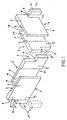
- Fig. 1 four are each identical Components made of polystyrene foam.
- the component 2 is opposite the component 1 rotated about a vertical axis by 180 °.
- a corresponding Mutual rotational position have the components 3 and 4, which are also opposite the two components 1 and 2 rotated about a horizontal axis by 180 ° and are arranged at right angles to it.
- Each of the plate-shaped components 1 to 4 has a first plate section 5 and a second plate section 6, the second plate section 6 half as much thick as the first plate section 5.
- reference numeral 7 is one on each the plate components 1 to 4 designated first step recess, the corresponds in shape and dimensions to the second thinner plate section 6.
- a second step recess 8 is in each case on the vertical as an edge recess Edge of the first plate section 5 is formed and extends over half Length of the vertical plate height, with its horizontal depth equal to the plate thickness of the first plate section 5. Accordingly, through the step recess 8 a square step surface 9 is formed. Through the first step recess 7 step surfaces formed are designated in FIG. 1 by the reference number 10.
- a component made of polysterol foam referred to which corresponds in shape and dimensions to the step recess 8.
- a Such component 11 can be separated from a section 11 'of the win first plate section 5 according to a dividing line 12.
- FIG. 2 where with reference number 13 in horizontal Slots provided are designated.
- Those in the thinner Slits 13 introduced into the second plate section 6 serve for formation of predetermined breaking points that allow the horizontal length of the thinner second Plate section 6 each with less effort by breaking off sections To shorten.
- a slot corresponding to the slots 13 could also be along the length shown in FIG. 1 shown section line 12 to form a predetermined breaking point or at least one Guide for a cutting tool can be formed, thereby separating the plate section 11 'would be much easier.
- the second plate sections 6 are the components 3 and 4 shortened compared to the second plate sections 6 of the components 1 and 2, this shortening corresponds to two grid lengths.
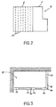
- FIGS. 3 to 5 in which different through Components according to FIGS. 1 and 2 producible bathtub linings in one Top view are shown.
- FIG. 3 is an angular by components 14 to 19 joined together Cladding for a set up in a wall corner 20, not shown in FIG. 3 Bathtub formed.
- 40 and 41 are the step surface 9 corresponding overlap sections designated.
- Fig. 4 shows a tub cladding formed from components 21 to 28 with two Angles through which a bathtub set up on a wall 29 can be enclosed.
- a tub cladding could be made from a single straight wall consist of a bathtub set up in a wall niche covered on the long side is.
- FIGS. 1 and 2 are used for their processing assembled so that the step surface 10 of the step recesses 7 come into contact with each other so that the step recesses 7 of the respective Components through the thinner second plate section 6 of the adjacent Component to be filled in completely. Furthermore, the mutual Recesses 8, the step surfaces 9 of components to be joined together brought to coincide with one another, this, as from FIGS. 3 to 5 emerges, both in a straight line of the components and by Joining at a right angle can be achieved.
- the individual components are preferably glued together.
- Embodiment can be carried out in a simple manner that of underneath the thinner second plate sections 6 of plates to be joined together Using the predetermined breaking points, plate sections are separated, with the horizontal The length of the sections to be separated is the same for both plates.
- a continuous vertical abutting surface between the edge of the first plate section and an adjacent installation wall the panel section 11 'can be removed and for example to fill a recess 8 one to another Installation wall adjacent component can be used.
- a cuboid component corresponding to the foam component 11 could also be used to complete the kit for the installation of bath tub cladding be provided as an additional component with the recesses 8 at joints between installation walls and panel components are fillable.
Landscapes
- Health & Medical Sciences (AREA)
- Public Health (AREA)
- Epidemiology (AREA)
- General Health & Medical Sciences (AREA)
- Finishing Walls (AREA)
- Residential Or Office Buildings (AREA)
Applications Claiming Priority (2)
| Application Number | Priority Date | Filing Date | Title |
|---|---|---|---|
| DE19649120 | 1996-11-27 | ||
| DE1996149120 DE19649120A1 (de) | 1996-11-27 | 1996-11-27 | Bausatz für die Errichtung von Badewannenverkleidungen |
Publications (1)
| Publication Number | Publication Date |
|---|---|
| EP0845236A1 true EP0845236A1 (fr) | 1998-06-03 |
Family
ID=7812918
Family Applications (1)
| Application Number | Title | Priority Date | Filing Date |
|---|---|---|---|
| EP97119390A Withdrawn EP0845236A1 (fr) | 1996-11-27 | 1997-11-06 | Série d'éléments pour habillage de baignoire |
Country Status (2)
| Country | Link |
|---|---|
| EP (1) | EP0845236A1 (fr) |
| DE (1) | DE19649120A1 (fr) |
Cited By (2)
| Publication number | Priority date | Publication date | Assignee | Title |
|---|---|---|---|---|
| FR2873561A1 (fr) * | 2004-07-27 | 2006-02-03 | Allibert Group Sa | Habillage universel ajustable en longueur et largeur pour tout type de baignoire. |
| GB2592939A (en) * | 2020-03-11 | 2021-09-15 | Sweeten Gavin | T-Panel |
Families Citing this family (2)
| Publication number | Priority date | Publication date | Assignee | Title |
|---|---|---|---|---|
| PT1093749E (pt) | 1999-10-22 | 2002-06-28 | Kaldewei Franz Gmbh & Co | Dispositivo sanitario |
| GB201911841D0 (en) * | 2019-08-19 | 2019-10-02 | Procare Shower And Bathroom Centre Ltd | Panel for use in bathroom environment |
Citations (3)
| Publication number | Priority date | Publication date | Assignee | Title |
|---|---|---|---|---|
| DE8507760U1 (de) * | 1985-03-15 | 1985-05-30 | Menden, Leo, 5342 Rheinbreitbach | Bade- oder Brausewannenträger |
| DE8906225U1 (de) * | 1989-03-03 | 1989-08-03 | Ucosan B.V., Roden | Vorrichtung zum Abstützen und Verkleiden einer Badewanne od.dgl. |
| DE29619552U1 (de) * | 1996-11-11 | 1997-02-20 | Saarpor Klaus Eckhardt GmbH Neunkirchen Kunststoffe KG, 66539 Neunkirchen | Plattenartiges Bauelement aus Schaumstoff insbesondere zur Verwendung für eine Wannenblende |
-
1996
- 1996-11-27 DE DE1996149120 patent/DE19649120A1/de not_active Withdrawn
-
1997
- 1997-11-06 EP EP97119390A patent/EP0845236A1/fr not_active Withdrawn
Patent Citations (3)
| Publication number | Priority date | Publication date | Assignee | Title |
|---|---|---|---|---|
| DE8507760U1 (de) * | 1985-03-15 | 1985-05-30 | Menden, Leo, 5342 Rheinbreitbach | Bade- oder Brausewannenträger |
| DE8906225U1 (de) * | 1989-03-03 | 1989-08-03 | Ucosan B.V., Roden | Vorrichtung zum Abstützen und Verkleiden einer Badewanne od.dgl. |
| DE29619552U1 (de) * | 1996-11-11 | 1997-02-20 | Saarpor Klaus Eckhardt GmbH Neunkirchen Kunststoffe KG, 66539 Neunkirchen | Plattenartiges Bauelement aus Schaumstoff insbesondere zur Verwendung für eine Wannenblende |
Cited By (3)
| Publication number | Priority date | Publication date | Assignee | Title |
|---|---|---|---|---|
| FR2873561A1 (fr) * | 2004-07-27 | 2006-02-03 | Allibert Group Sa | Habillage universel ajustable en longueur et largeur pour tout type de baignoire. |
| GB2592939A (en) * | 2020-03-11 | 2021-09-15 | Sweeten Gavin | T-Panel |
| GB2592939B (en) * | 2020-03-11 | 2024-05-15 | Sweeten Gavin | Adjustable Tileable Bath Panel |
Also Published As
| Publication number | Publication date |
|---|---|
| DE19649120A1 (de) | 1998-05-28 |
Similar Documents
| Publication | Publication Date | Title |
|---|---|---|
| DE4227170A1 (de) | Baublock | |
| DE2733283A1 (de) | Neues profil und verbindungsstueck fuer montagesysteme | |
| DE1965012A1 (de) | Bauelemente,insbesondere Spielzeug- und Hochbau-Bauelemente | |
| DE69530226T2 (de) | Isolierendes bauelement oder baustein. | |
| DE2739017A1 (de) | Mauer sowie mauerelemente mit bloecken | |
| EP0845236A1 (fr) | Série d'éléments pour habillage de baignoire | |
| DE2535980C3 (de) | Wandkonstruktion mit mindestens zwei an einem gemeinsamen Pfosten angeschlossenen, im Winkel zueinander verlaufenden Wandbauteilen | |
| DE69025714T2 (de) | Satz von sich ineinanderfügenden modulelementen zum bau von trennwänden | |
| EP0507970A1 (fr) | Eléments de construction pour la réalisation d'ouvrages | |
| DE1041672B (de) | Bausteinsatz | |
| DE19616622B4 (de) | Bausatz zur Erstellung von Stützmauern | |
| DE19618847C2 (de) | Bausatz zum Erstellen eines Blockhauses | |
| EP1569312A2 (fr) | Element de construction pour une canalisation de cables | |
| DE2814192A1 (de) | Steckbausystem fuer spielzwecke | |
| EP0584659B1 (fr) | Ensemble d'éléments pour la fabrication d'une paroi en briques de verre | |
| EP0744141B1 (fr) | Elément pour système modulaire de meubles | |
| DE8601945U1 (de) | Aus geblähten Stoffen bestehendes Bauelement | |
| DE3904600A1 (de) | Mauerstein fuer installationsschlitze | |
| DE102004050246A1 (de) | Systembauelement | |
| DE2900004C2 (de) | Plattenförmiges Bauteil | |
| DE68904557T2 (de) | Teilelement zur herstellung einer kantenform. | |
| DE2227351A1 (de) | Mauerstein und hieraus hergestellte wand | |
| DE3118755A1 (de) | "bauelement, sowie hieraus hergestellte baugruppen" | |
| DE842774C (de) | Mit Randausnehmungen versehener, teilweise ineinander steckbarer Baustein eines Zusammensetz- oder Bauspiels | |
| DE29619552U1 (de) | Plattenartiges Bauelement aus Schaumstoff insbesondere zur Verwendung für eine Wannenblende |
Legal Events
| Date | Code | Title | Description |
|---|---|---|---|
| PUAI | Public reference made under article 153(3) epc to a published international application that has entered the european phase |
Free format text: ORIGINAL CODE: 0009012 |
|
| AK | Designated contracting states |
Kind code of ref document: A1 Designated state(s): DE FR NL |
|
| AKX | Designation fees paid |
Free format text: DE FR NL |
|
| RBV | Designated contracting states (corrected) |
Designated state(s): DE FR NL |
|
| STAA | Information on the status of an ep patent application or granted ep patent |
Free format text: STATUS: THE APPLICATION IS DEEMED TO BE WITHDRAWN |
|
| 18D | Application deemed to be withdrawn |
Effective date: 19981204 |