EP0845300A2 - Flüssigkeitszerstäubungsdüse - Google Patents
Flüssigkeitszerstäubungsdüse Download PDFInfo
- Publication number
- EP0845300A2 EP0845300A2 EP97119735A EP97119735A EP0845300A2 EP 0845300 A2 EP0845300 A2 EP 0845300A2 EP 97119735 A EP97119735 A EP 97119735A EP 97119735 A EP97119735 A EP 97119735A EP 0845300 A2 EP0845300 A2 EP 0845300A2
- Authority
- EP
- European Patent Office
- Prior art keywords
- liquid
- cylindrical chamber
- supplying pipe
- orifice
- atomizing nozzle
- Prior art date
- Legal status (The legal status is an assumption and is not a legal conclusion. Google has not performed a legal analysis and makes no representation as to the accuracy of the status listed.)
- Withdrawn
Links
- 239000007788 liquid Substances 0.000 title claims abstract description 106
- 239000011344 liquid material Substances 0.000 abstract description 19
- 239000011343 solid material Substances 0.000 abstract description 9
- 241000009298 Trigla lyra Species 0.000 abstract 1
- 239000007921 spray Substances 0.000 description 25
- 239000012530 fluid Substances 0.000 description 7
- 239000002245 particle Substances 0.000 description 7
- 238000000889 atomisation Methods 0.000 description 4
- 239000010408 film Substances 0.000 description 3
- 239000002699 waste material Substances 0.000 description 3
- XLYOFNOQVPJJNP-UHFFFAOYSA-N water Substances O XLYOFNOQVPJJNP-UHFFFAOYSA-N 0.000 description 3
- 239000011248 coating agent Substances 0.000 description 2
- 230000000694 effects Effects 0.000 description 2
- 239000000843 powder Substances 0.000 description 2
- 238000010008 shearing Methods 0.000 description 2
- 238000001694 spray drying Methods 0.000 description 2
- 238000005507 spraying Methods 0.000 description 2
- 239000010409 thin film Substances 0.000 description 2
- 230000002411 adverse Effects 0.000 description 1
- 230000009286 beneficial effect Effects 0.000 description 1
- 238000005422 blasting Methods 0.000 description 1
- 238000004140 cleaning Methods 0.000 description 1
- 238000000576 coating method Methods 0.000 description 1
- 238000002485 combustion reaction Methods 0.000 description 1
- 230000007423 decrease Effects 0.000 description 1
- 230000007547 defect Effects 0.000 description 1
- 238000009826 distribution Methods 0.000 description 1
- 238000001704 evaporation Methods 0.000 description 1
- 239000002657 fibrous material Substances 0.000 description 1
- 239000000463 material Substances 0.000 description 1
- 238000013021 overheating Methods 0.000 description 1
- 238000005453 pelletization Methods 0.000 description 1
- 238000002360 preparation method Methods 0.000 description 1
- 238000007789 sealing Methods 0.000 description 1
- 239000003566 sealing material Substances 0.000 description 1
Images


Classifications
-
- B—PERFORMING OPERATIONS; TRANSPORTING
- B05—SPRAYING OR ATOMISING IN GENERAL; APPLYING FLUENT MATERIALS TO SURFACES, IN GENERAL
- B05B—SPRAYING APPARATUS; ATOMISING APPARATUS; NOZZLES
- B05B7/00—Spraying apparatus for discharge of liquids or other fluent materials from two or more sources, e.g. of liquid and air, of powder and gas
- B05B7/02—Spray pistols; Apparatus for discharge
- B05B7/04—Spray pistols; Apparatus for discharge with arrangements for mixing liquids or other fluent materials before discharge
- B05B7/0416—Spray pistols; Apparatus for discharge with arrangements for mixing liquids or other fluent materials before discharge with arrangements for mixing one gas and one liquid
- B05B7/0441—Spray pistols; Apparatus for discharge with arrangements for mixing liquids or other fluent materials before discharge with arrangements for mixing one gas and one liquid with one inner conduit of liquid surrounded by an external conduit of gas upstream the mixing chamber
- B05B7/0475—Spray pistols; Apparatus for discharge with arrangements for mixing liquids or other fluent materials before discharge with arrangements for mixing one gas and one liquid with one inner conduit of liquid surrounded by an external conduit of gas upstream the mixing chamber with means for deflecting the peripheral gas flow towards the central liquid flow
-
- B—PERFORMING OPERATIONS; TRANSPORTING
- B05—SPRAYING OR ATOMISING IN GENERAL; APPLYING FLUENT MATERIALS TO SURFACES, IN GENERAL
- B05B—SPRAYING APPARATUS; ATOMISING APPARATUS; NOZZLES
- B05B7/00—Spraying apparatus for discharge of liquids or other fluent materials from two or more sources, e.g. of liquid and air, of powder and gas
- B05B7/02—Spray pistols; Apparatus for discharge
- B05B7/10—Spray pistols; Apparatus for discharge producing a swirling discharge
Definitions
- the present invention relates to a liquid atomizing nozzle used in the field of spray drying, humid pelletizing, coating, combustion and the like, and the nozzle is especially suited for atomizing liquid materials having high viscosity or containing bulky solid materials.
- Liquid atomizing nozzles having compressed air power sources are widely used e. g. in spray drying and coating works of liquid materials.
- the nozzle is basically composed of a liquid supplying pipe and a compressed air supplying pipe coaxially arranged outside of the liquid supplying pipe.
- the amount of liquid processed by this kind of coaxial double-pipe liquid atomizing nozzles is usually from several liter/h to dozens liter/h , because atomizing features of the nozzles worsen when the nozzle is enlarged analogously in proportion to an increased amount of liquid to be processed (increased ratio of compressed air and flattened distribution of atomized liquid particles).
- liquid atomizing nozzles of this type are not suitable for atomizing liquids of high viscosity of tens of thousands cP (mPa ⁇ s) or those containing bulky solid materials. Further, atomizing nozzles of this type are too narrow in spray angles to be employed as atomizing equipments of spray dryers and so they can not substitute for pressurized spray nozzles having spray angles of larger than 70 degree.
- the present invention is directed to provide a liquid atomizing nozzle capable of atomizing liquid materials of high viscosity or containing bulky solid materials charged not only at a small feed rate but also at several thousands liter/h rate, by which the liquid is atomized and sprayed uniformly with predetermined spray angles.
- the liquid atomizing nozzle comprises a liquid supplying pipe, a cylindrical chamber for whirling of air being connected at one end with the liquid supplying pipe, having an inside diameter larger than the inside diameter of the liquid supplying pipe, and being provided with one or more through holes for passing through pressurized air in the direction tangential to the circular internal surface of the cylindrical chamber, an orifice disposed at the top of the cylindrical chamber and having a circular opening being smaller than the inside diameter of the cylindrical chamber, and an external cylinder covering the cylindrical chamber and at least a part of the liquid supplying pipe and being provided with a pressurized air supplying pipe.
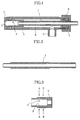
- Fig.1 is a longitudinal section of the liquid atomizing nozzle according to the present invention
- Fig.2 is a longitudinal section of the liquid supplying pipe
- Fig.3 is a longitudinal section of the cylindrical chamber
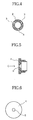
- Fig.4 is a sectional view seen along A-A of the cylindrical chamber of Fig.3
- Fig.5 is a longitudinal section of the orifice
- Fig.6 is a view of the orifice of Fig.5 seen from the direction C
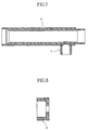
- Fig.7 is a longitudinal section of the external cylinder
- Fig.8 is a longitudinal section of a seal cap
- Fig.9 is a longitudinal section of the liquid atomizing nozzle equipped with a reverse conical body and a disc-type liquid distributor
- Fig.10 is a side view of the reverse conical body
- Fig.11 is sectional view of the orifice used in combination with the reverse conical body
- Fig.12 is a top view of the disc-type liquid distributor
- Fig.13 is
- Reference number 1 indicates the liquid supplying pipe, and the pipe is connected with the cylindrical chamber for whirling of air 2 at one end exemplified by the left end in Fig.1.
- the cylindrical chamber 2 has a cylindrical shape having an inside diameter larger than the inside diameter of the liquid supplying pipe 1, and is provided at the cylindrical portion with one or more through holes 3 for passing through pressurized air in the direction tangential to the circular internal surface of the cylindrical chamber.
- a plurality of the through holes 3 for passing through pressurized air may be disposed along the same circumference (c.f. Fig.4) or in rows in axial direction of the cylindrical chamber (e.g. at A-A and B-B in Fig. 3).
- a plurality of through holes may be arranged along the same circumference and a plurality of circumferential arrangements may be disposed in rows in the axial direction.
- the orifice 4 having the circular opening 5 with a diameter smaller than the inside diameter of the cylindrical chamber is disposed at the head of the cylindrical chamber 2.
- the external cylinder 6 is so disposed as to cover the cylindrical chamber 2 and at least a part of the liquid supplying pipe 1, and the pressurized air supplying pipe 7 is connected therewith.
- Reference number 9 is a seal for sealing the other end of the external cylinder 6, and reference number 8 is a seal cap.
- the liquid atomizing nozzle according to the invention can be assembled easily by steps of inserting the liquid supplying pipe 1 into a connection opening disposed at the bottom of the cylindrical chamber 2, inserting into the external cylinder 6 the cylindrical chamber attached with the liquid supplying pipe, fastening the orifice 4 to the front end of the external cylinder 6 to fasten the front end of the cylindrical chamber 2, engaging the seal cap 8 having a through hole for the liquid supplying pipe 1 at the back end of the external cylinder 6; and making the assembled nozzle air-tight or water-tight by means of applying appropriately sealing materials. Disassembling or exchanging such parts as the cylindrical chamber 2 and/or orifice 4 can be done easily.
- Liquid material supplied into the cylindrical chamber 2 through the liquid supplying pipe 1 is revolved and accelerated in the cylindrical chamber by virtue of the pressurized air coming in at a high speed from the through holes 3 in the direction tangential to the circular internal surface of the cylindrical chamber.
- the accelerated revolving liquid material moves by means of centrifugal force toward the internal surface of the cylindrical chamber, becomes a thin film, moves toward the circular opening 5, and is sprayed therefrom accompanied by a whirling air stream.
- fine liquid particles are accompanied by an air stream ejected into the cylindrical chamber.
- Other liquid flows in a thin film state along the internal surface of the cylindrical chamber and is atomized at the opening 5 of orifice and sprayed.
- the nozzle has structural features that the pressurized air and the liquid are maintained separately until reaching at the head of double-pipe fluid atomizing nozzle, and suction, shearing and atomizing occur instantly upon contacting at the front end of the double-pipe.
- the pressurized air discharged in high speed from an outside pipe induces highly negative pressure around the front end portion to cause the liquid being sucked from the inner pipe and sheared.
- due to simultaneous sucking of air from outside of the system a large portion of kinetic energy of the compressed air is wasted for accelerating the external air.
- the nozzle has the structural features that the liquid material is revolved and accelerated in the cylindrical chamber by the ejected pressurized air to be atomized partly, and the remaining portion is forwarded to the orifice under a film state of accelerated revolution.
- a compressed air of 3 kg/cm 2 pressure is employed, around 2 kg/cm 2 pressure is consumed in the cylindrical chamber and the remaining pressure becomes the kinetic energy for spraying from the orifice, though the ratio varies in accordance with ratios of the area of circular opening 5 of the orifice to the total cross-sectional area of through holes 3 for compressed air.
- the portion of energy consumed for atomizing liquid is larger than that of conventional spray nozzles.
- the ratios of the necessary amount of the compressed air to the amount of liquid varies widely in accordance with the properties of the liquid (viscosity, surface tension, size of solid material, etc.) and the average particle sizes desired.
- the compressed air employable is 4-7 kg/cm 2 pressure, as general purpose air compressors usually have 7 kg/cm 2 specifications.
- Air through holes of the cylindrical chamber are set to have a total cross-sectional area allowing to pass through a predetermined amount of air under a pressure difference of 1 kg/cm 2 lower than the set air pressure.
- the orifice is set to have an opening area capable of passing a predetermined amount of air under 0.5-1.5 kg/cm 2 pressure difference.
- the ejecting air at the opening of orifice preferably has a velocity corresponding to 0.5-1.5 kg/cm 2 pressure difference. In order to attain desirous atomization with such a small amount of pressurized air, it is quite important to select properly the (total) cross-sectional area of the air through holes in the cylindrical chamber and opening area of the orifice.
- the ratio of the diameter of the circular opening 5 of the orifice inside diameter of the cylindrical chamber 2 is in the range of 1 : 1.5-4.0, and the ratio of the area the circular opening 5 of the orifice/total cross-sectional area of through holes 3 opened tangentially to the circular internal surface of the cylindrical chamber is in the range of 1 : 0.2-1.0.
- the nozzle according to the present invention can employ an enlarged diameter liquid supplying pipe thanks to being scarcely affected on the atomizing features by the pipe diameters, and the diameter of orifice can also be enlarged. Accordingly, it is possible to atomize liquid materials not only in large amountsor of high viscosity but also containing coarse solid materials. Since the atomized liquid particles possess higher revolving momentum and lower axial velocity in comparison with those of conventional nozzles, the atomized liquid particles can be spread so broadly as to be beneficial for usages in spray dryers.
- a reverse conical body 10 is disposed coaxially inside of the opening 5 of the orifice 4 as shown in Fig.9, which enables a spray angle of near to that of pressure spray nozzles.
- Fig.10 shows the reverse conical body 10 attached to the connecting rod 11.
- the reverse conical body 10 can be disposed coaxially inside of the opening 5 of the orifice 4.
- the circular opening 5 of the orifice 4 is preferably shaped into the reverse conical shape, as shown in Fig.11.
- a liquid material passed into the cylindrical chamber 2 from the liquid supplying pipe 1 is dispersed, revolved and accelerated in the cylindrical chamber by virtue of the pressurized air coming into at a high speed from the through holes 3 in the direction tangential to the circular internal surface of the cylindrical chamber, and is transformed into a thin liquid film through centrifugal force, and transferred toward the internal surface of the cylindrical chamber.
- a disc-type liquid distributor 12 having a plurality of liquid ejecting holes 13 (top view: Fig.12; sectional view: Fig.13) placed evenly and concentrically is preferably disposed (in the cylindrical chamber) at a place between the one or more through holes 3 for passing through pressurized air in the direction tangential to the circular internal surface of the cylindrical chamber and the connecting portion of the liquid supplying pipe (cf. Fig.9).
- a disc-type liquid revolving plate 15, shown by Fig.14 in top view and by Fig.15 in side view, having one or more of inclined slits 16 circumferentially for revolving liquid is disposed effectively (in the cylindrical chamber) at a place between the one or more through holes for passing through pressurized air in the direction tangential to the circular internal surface of the cylindrical chamber and the connecting portion of the liquid supplying pipe.
- a disc-type liquid revolving plate 15 shown by Fig.14 in top view and by Fig.15 in side view, having one or more of inclined slits 16 circumferentially for revolving liquid is disposed effectively (in the cylindrical chamber) at a place between the one or more through holes for passing through pressurized air in the direction tangential to the circular internal surface of the cylindrical chamber and the connecting portion of the liquid supplying pipe.
- the arrangement of the inclined slit 16 enables pressurized supply of the liquid and decreases greatly the amount of pressurized air, which solves the essential defect of conventional double-pipe fluid atomizing nozzles.
- the present nozzle can be installed in existing spray dryers in place of pressurized spray nozzles, and atomization of highly viscous liquid materials unable to be atomized so far, becomes feasible.
- the nozzle When the present nozzle is employed for a spray dryer, the nozzle is to be inserted close to the hot air supplying portion. In that case, since the cylindrical chamber 2 and the liquid supplying pipe 1 are covered with the external cylinder 6, overheating and charring of the liquid can be prevented effectively.
- parts having respectively several kinds of cross-sectional area enable nozzles capable of being combined suitably for processing various liquid materials.
- preparation of tens of kinds of nozzles of the same series are required usually, since the amount of liquid material to be processed by one specified nozzle is narrowly restricted.
- 5 kinds of nozzle openings corresponding to orifice diameters can manage liquid materials amounting from several liter/h - several thousands liter/h .
- nozzles having optional lengths for the liquid supply pipe and for the external cylinder can be fabricated, and even extremely lengthy ones are manageable by mere increases in costs added for the increased weight of the pipe materials. Even when the head portion of the nozzle is inserted into high temperature regions of a spray dryer or drying-incinerator, connecting portions of the liquid supplying pipe and pressurized air supplying pipe remain outside of the inserting portion of nozzle, which enables easy releasing of connection pipes and hoses. Further, since the nozzle is overhauled easily for cleaning without using special tools, the nozzle is suitable for uses in food industries and changeover of multiple products.
- Waste liquors of SHOUCHU spirit contains 90% or more of water and includes grain shells of several mm and fibrous materials of several tens mm. Though those apparently solid materials as dehydrated activated sludges can be incinerated with rotary kilns, waste liquors of SHOUCHU spirit are not treated similarly because of being truly liquid materials. However, by use of the liquid atomizing nozzle according to the present invention having the below mentioned specification, waste liquors of SHOUCHU spirit could be atomized and sprayed in a rotary kiln for evaporating the main portion of the water, and the residue was deposited on the kiln wall.
- the deposit was a solid material containing about 50% of water and resembled to dehydrated activated sludges, which was easily incinerated in the kiln and turned to ash. Since bulky solid materials hinder the atomization, they must be crushed for processing with a spray dryer, but they cause almost no trouble in incinerating in a kiln.
- a viscous liquid of over 20,000 cP(mPa ⁇ s) which was unable to be atomized by use of a spray dryer with a small pressurized spray nozzle was turned to dried powder by use of the liquid atomizing nozzle according to the present invention having the below mentioned specification.
- the pressurized spray nozzle exhibited a spray angle of larger than 70° for a low viscosity liquid.
- the present atomizing nozzle without the reverse conical body exhibited about 30° of spray angle but provided an atomized liquid capable of being dried without adhesion and turning into dried powder of good quality.
Landscapes
- Nozzles (AREA)
Applications Claiming Priority (2)
| Application Number | Priority Date | Filing Date | Title |
|---|---|---|---|
| JP316637/96 | 1996-11-27 | ||
| JP31663796A JPH10156230A (ja) | 1996-11-27 | 1996-11-27 | 液体噴霧ノズル |
Publications (2)
| Publication Number | Publication Date |
|---|---|
| EP0845300A2 true EP0845300A2 (de) | 1998-06-03 |
| EP0845300A3 EP0845300A3 (de) | 1999-01-20 |
Family
ID=18079259
Family Applications (1)
| Application Number | Title | Priority Date | Filing Date |
|---|---|---|---|
| EP97119735A Withdrawn EP0845300A3 (de) | 1996-11-27 | 1997-11-11 | Flüssigkeitszerstäubungsdüse |
Country Status (3)
| Country | Link |
|---|---|
| EP (1) | EP0845300A3 (de) |
| JP (1) | JPH10156230A (de) |
| CA (1) | CA2221897A1 (de) |
Cited By (4)
| Publication number | Priority date | Publication date | Assignee | Title |
|---|---|---|---|---|
| CN107126831A (zh) * | 2017-06-20 | 2017-09-05 | 佛山市三水新明珠建陶工业有限公司 | 一种用于sncr脱硝系统的喷射器 |
| CN108114822A (zh) * | 2018-01-25 | 2018-06-05 | 山东农业大学 | 一种在线调控雾滴粒径的防飘移气力雾化喷头及控制方法 |
| WO2021197825A1 (en) * | 2020-03-30 | 2021-10-07 | Sulzer Mixpac Ag | Spray nozzle |
| CN113834704A (zh) * | 2020-06-23 | 2021-12-24 | 上海伯顿医疗设备有限公司 | 一种全自动旋转料箱雾化器式染色封片一体机 |
Families Citing this family (4)
| Publication number | Priority date | Publication date | Assignee | Title |
|---|---|---|---|---|
| AU2004251453A1 (en) * | 2003-06-27 | 2005-01-06 | Recticel | Method for producing a moulded article comprising a sprayed polyurethane layer |
| BRPI0713490A2 (pt) * | 2006-06-21 | 2012-01-24 | Clyde Bergemann Inc | orifìcio variável para bocal de licor negro |
| CN103316793B (zh) * | 2013-06-19 | 2016-07-06 | 安徽艾可蓝节能环保科技有限公司 | 一种气助式雾化喷嘴 |
| CN103657913A (zh) * | 2013-11-30 | 2014-03-26 | 无锡大阿福信息科技有限公司 | 一种喷雾器喷嘴结构 |
Family Cites Families (3)
| Publication number | Priority date | Publication date | Assignee | Title |
|---|---|---|---|---|
| US3897007A (en) * | 1973-09-10 | 1975-07-29 | Joseph G Roy | Apparatus for atomizing liquid fuels for the combustion process |
| JPS5926348B2 (ja) * | 1976-12-03 | 1984-06-26 | 三菱プレシジヨン株式会社 | 流体の微粒化分散装置 |
| US4422900A (en) * | 1981-11-25 | 1983-12-27 | Olin Corporation | Spray drying apparatus for available chlorine-containing compounds |
-
1996
- 1996-11-27 JP JP31663796A patent/JPH10156230A/ja active Pending
-
1997
- 1997-11-11 EP EP97119735A patent/EP0845300A3/de not_active Withdrawn
- 1997-11-21 CA CA002221897A patent/CA2221897A1/en not_active Abandoned
Non-Patent Citations (1)
| Title |
|---|
| None |
Cited By (6)
| Publication number | Priority date | Publication date | Assignee | Title |
|---|---|---|---|---|
| CN107126831A (zh) * | 2017-06-20 | 2017-09-05 | 佛山市三水新明珠建陶工业有限公司 | 一种用于sncr脱硝系统的喷射器 |
| CN107126831B (zh) * | 2017-06-20 | 2023-04-21 | 佛山市三水新明珠建陶工业有限公司 | 一种用于sncr脱硝系统的喷射器 |
| CN108114822A (zh) * | 2018-01-25 | 2018-06-05 | 山东农业大学 | 一种在线调控雾滴粒径的防飘移气力雾化喷头及控制方法 |
| CN108114822B (zh) * | 2018-01-25 | 2023-09-15 | 山东农业大学 | 一种在线调控雾滴粒径的防飘移气力雾化喷头及控制方法 |
| WO2021197825A1 (en) * | 2020-03-30 | 2021-10-07 | Sulzer Mixpac Ag | Spray nozzle |
| CN113834704A (zh) * | 2020-06-23 | 2021-12-24 | 上海伯顿医疗设备有限公司 | 一种全自动旋转料箱雾化器式染色封片一体机 |
Also Published As
| Publication number | Publication date |
|---|---|
| JPH10156230A (ja) | 1998-06-16 |
| CA2221897A1 (en) | 1998-05-27 |
| EP0845300A3 (de) | 1999-01-20 |
Similar Documents
| Publication | Publication Date | Title |
|---|---|---|
| US5344078A (en) | Nozzle assembly for HVLP spray gun | |
| EP0408801B1 (de) | Sprühtrocknungsvorrichtung | |
| EP0509367B1 (de) | Verteilerscheibe für Hochdurchfluss-Niederdruck-Sprühpistole | |
| US4456181A (en) | Gas liquid mixing nozzle | |
| US5227017A (en) | Spray drying apparatus equipped with a spray nozzle unit | |
| EP1160015A3 (de) | Düse zur Druckluftzerstäubung | |
| JP6218249B2 (ja) | 空気アシスト式フルコーンスプレーノズル組立体 | |
| US6969012B2 (en) | Low pressure atomizer for difficult to disperse solutions | |
| JPS6161660A (ja) | 粘性液体を霧化しスプレイ乾燥する装置および方法 | |
| CA1255719A (en) | Flow-amplifying liquid-atomizing nozzle | |
| HUE031504T2 (en) | Improved Inner Air Nozzle Nozzle Arrangement | |
| CA2209560A1 (en) | Improved flat fan spray nozzle | |
| RU2305605C2 (ru) | Гранулятор с псевдоожиженным слоем и используемый в нем распылитель | |
| EP0845300A2 (de) | Flüssigkeitszerstäubungsdüse | |
| JPS59152838A (ja) | 木屑,木繊維等から成る混合物を連続的に膠付けするための方法及び混合装置 | |
| JP2005291530A (ja) | 噴霧乾燥装置、粉体の乾燥方法およびフェライト粒の製造方法 | |
| GB2181975A (en) | Nozzle for atomization of fluids | |
| US3795348A (en) | Device for delivering particulate material | |
| RU2513077C1 (ru) | Вихревая распылительная сушилка для дисперсных материалов | |
| RU2637588C1 (ru) | Вихревая распылительная сушилка для дисперсных материалов | |
| US4410140A (en) | Atomizer and method | |
| RU2326303C1 (ru) | Распылительная сушилка | |
| RU2335713C1 (ru) | Вихревая испарительно-сушильная камера с инертной насадкой | |
| US5931387A (en) | Liquid atomizer | |
| SU1072825A3 (ru) | Способ распылительной сушки и распылительна сушилка |
Legal Events
| Date | Code | Title | Description |
|---|---|---|---|
| PUAI | Public reference made under article 153(3) epc to a published international application that has entered the european phase |
Free format text: ORIGINAL CODE: 0009012 |
|
| AK | Designated contracting states |
Kind code of ref document: A2 Designated state(s): AT BE CH DE DK ES FI FR GB GR IE IT LI LU MC NL PT SE |
|
| AX | Request for extension of the european patent |
Free format text: AL;LT;LV;MK;RO;SI |
|
| PUAL | Search report despatched |
Free format text: ORIGINAL CODE: 0009013 |
|
| AK | Designated contracting states |
Kind code of ref document: A3 Designated state(s): AT BE CH DE DK ES FI FR GB GR IE IT LI LU MC NL PT SE |
|
| AX | Request for extension of the european patent |
Free format text: AL;LT;LV;MK;RO;SI |
|
| STAA | Information on the status of an ep patent application or granted ep patent |
Free format text: STATUS: THE APPLICATION HAS BEEN WITHDRAWN |
|
| 18W | Application withdrawn |
Withdrawal date: 19990621 |
|
| R18W | Application withdrawn (corrected) |
Effective date: 19990618 |