EP0845404B1 - Feuerschutzwand für eine Kraftfahrzeugkarosserie mit einer Verstärkungsstütze - Google Patents
Feuerschutzwand für eine Kraftfahrzeugkarosserie mit einer Verstärkungsstütze Download PDFInfo
- Publication number
- EP0845404B1 EP0845404B1 EP19970402801 EP97402801A EP0845404B1 EP 0845404 B1 EP0845404 B1 EP 0845404B1 EP 19970402801 EP19970402801 EP 19970402801 EP 97402801 A EP97402801 A EP 97402801A EP 0845404 B1 EP0845404 B1 EP 0845404B1
- Authority
- EP
- European Patent Office
- Prior art keywords
- partition
- wall
- support
- steering mechanism
- vehicle
- Prior art date
- Legal status (The legal status is an assumption and is not a legal conclusion. Google has not performed a legal analysis and makes no representation as to the accuracy of the status listed.)
- Expired - Lifetime
Links
- 238000005192 partition Methods 0.000 claims description 36
- XAGFODPZIPBFFR-UHFFFAOYSA-N aluminium Chemical compound [Al] XAGFODPZIPBFFR-UHFFFAOYSA-N 0.000 claims description 4
- 229910052782 aluminium Inorganic materials 0.000 claims description 4
- 230000003014 reinforcing effect Effects 0.000 claims 4
- 239000004411 aluminium Substances 0.000 claims 1
- 230000002787 reinforcement Effects 0.000 description 8
- 230000004308 accommodation Effects 0.000 description 1
- 230000005540 biological transmission Effects 0.000 description 1
- 238000013016 damping Methods 0.000 description 1
- 230000004807 localization Effects 0.000 description 1
- 230000001737 promoting effect Effects 0.000 description 1
Images


Classifications
-
- B—PERFORMING OPERATIONS; TRANSPORTING
- B62—LAND VEHICLES FOR TRAVELLING OTHERWISE THAN ON RAILS
- B62D—MOTOR VEHICLES; TRAILERS
- B62D25/00—Superstructure or monocoque structure sub-units; Parts or details thereof not otherwise provided for
- B62D25/08—Front or rear portions
- B62D25/14—Dashboards as superstructure sub-units
-
- B—PERFORMING OPERATIONS; TRANSPORTING
- B62—LAND VEHICLES FOR TRAVELLING OTHERWISE THAN ON RAILS
- B62D—MOTOR VEHICLES; TRAILERS
- B62D25/00—Superstructure or monocoque structure sub-units; Parts or details thereof not otherwise provided for
- B62D25/08—Front or rear portions
- B62D25/082—Engine compartments
Definitions
- the invention relates to a transverse partition of an automobile body. equipped with a reinforcement support constituted by a profile mounted in support on said partition and which extends along the latter.
- the publication DE-A-4,138,393 describes a partition equipped with a support aluminum reinforcement for mounting seat belt anchors security.
- the section of the profile affects the shape of a slide of mounting of the seat belt fastening elements.
- the vibrations of said partition are transmitted from said steering box.
- the stress forces exerted by the steering axle on such a support unit in this case a steering rack are transmitted to the partition under form of vibrations. Damping these vibrations requires resources antivibration and reinforcement of the partition.
- the problem is solved in that two zones support of the support on the partition are adjacent to hollow compartments separated by a fixing wall of the vehicle steering mechanism.
- the partition thus produced has the advantage of being able to be used for vehicle equipment whose steering mechanism cannot be fitted on an auxiliary chassis or on a cross member connecting the side rails of the vehicle.
- the partition thus produced advantageously finds application on the compact vehicles on which the space freed up under the external part of the frame rails can be occupied by more structural frame elements resistant. Therefore the section of the longitudinal elements of the chassis may be advantageously increased.
- the aforementioned constructive provision offers also a possibility to locate the powertrain nearby of the partition and interestingly shorten the front structure of the vehicle.
- the reinforcement support and the steering mechanism constitute a separable mounting assembly from partition.
- the aforementioned arrangement thus allows the making of a subset preassembled likely to be incorporated on the vehicle assembly site.
- the reinforcement support consists of an extruded aluminum profile mounted in support along a first substantially vertical wall of the partition, limited downwards by a first fold from which the fixing wall of the mechanism bordered by hollow compartments and this last wall is fixed near a second fold of another oblique wall of the partition.
- the arrangement of hollow compartments near the attachment areas of the profile largely absorbs the vibrations of the mechanism of management.
- the transverse partition fitted in accordance with the invention with its support reinforcement contributes consequently to the soundproofing of the passenger compartment of the vehicle.
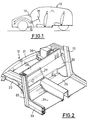
- the body 10 of a motor vehicle includes a passenger compartment 11 and a front structure 12 separated by a transverse partition 13 for supporting the dashboard and the steering mechanism 15.
- the structure 12 shown in more detail in Figure 2 has essentially two side rails 20 braced by a front crossmember 21 which are respectively connected to the front uprights 22.
- the uprights 22 are assembled to the longitudinal sections 23 of the longitudinal members associated with the floor 24.
- the front edge of floor 24 is juxtaposed to a partition firewall 25 which extends upwards through the transverse partition 26 fitted with the reinforcement support 27.
- the upper part 28 of the partition 26 constitutes for example a junction or support face of the plank edge not shown.
- the upper part 28 of the partition constitutes a wall which is substantially vertical, limited downwards by a first fold 29 from which extends in parallel an oblique wall 30 of the partition 26.
- the oblique wall 30 is itself limited by a second fold 31 of another oblique wall 32 of the partition 26.
- Reinforcement support 27 can be formed, as shown in Figures 4 and 5 by an extruded aluminum profile.
- the profile is mounted to bear respectively along the wall 28 to close to fold 29.
- the profile has a first fixing wing 33.
- the profile is also mounted in abutment along the oblique wall 32 to near fold 31.
- the profile has a second wing of fixing 34.
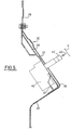
- the wings or support and fixing zones 33, 34 are adjacent, as well as that is shown in the drawing, to compartments 35, 36 separated by a wall of fixing 37 of the steering mechanism 40.
- the wall 37 carries two fixing nuts 41 for receiving the screws.
- mounting 42 of the steering mechanism 40 as shown in FIG. 4.
- the steering mechanism 40 and the profile constituting the support 27 are advantageously mounted on the vehicle as a preassembled assembly to outside the vehicle assembly line.
- the above arrangement is facilitated by the addition of fasteners on the walls 28, 32 in the purpose of promoting the use of fixing screws 45 in contact with the wings 33, 34 and proximity of the folds 29, 31 of the partition 26.
- fixing wall 37 of the mechanism 40 extends parallel to the wall 30 of the partition 26 and transversely to the longitudinal plane of the vehicle with a spacing "e" of said walls 37, 30 sufficient to promote the realization a "sound trap" which prevents the propagation of vibrations generated by the mechanism 40 inside the passenger compartment of the vehicle.
- the compartment 36 of the wall of fixing 37 carries the housing of a part of the mounting box of the steering mechanism. This accommodation is advantageously carried out by a cutout 41 made in the wall of compartment 36.
- FIG. 5 also shows the location of the actuation tail 42 of the steering rack control gear.
- the tail 42 is driven as is well known by an actuated steering shaft 43 by a steering wheel V.
Landscapes
- Engineering & Computer Science (AREA)
- Chemical & Material Sciences (AREA)
- Combustion & Propulsion (AREA)
- Transportation (AREA)
- Mechanical Engineering (AREA)
- Body Structure For Vehicles (AREA)
Claims (5)
- Quertrennwand einer Kraftfahrzeugkarosserie, die mit einem Verstärkungsträger (27) ausgestattet ist, der aus einem Profil besteht, das in Auflage auf der Trennwand (26) montiert ist und das sich entlang dieser letzteren erstreckt, dadurch gekennzeichnet, daß zwei Zonen der Auflage (33, 34) des Trägers (27) auf der Trennwand (26) an Hohlräume (35, 36) angrenzen, die von einer Wand (37) zur Befestigung eines Lenkgetriebes (40) des Fahrzeugs getrennt werden, wobei die Hohlräume und die Befestigungswand zum Verstärkungsträger gehören.
- Trennwand nach Anspruch 1, dadurch gekennzeichnet, daß der Verstärkungsträger (27) und das Lenkgetriebe (40) eine von der Trennwand trennbare Baugruppe bilden.
- Trennwand nach irgendeinem der Ansprüche 1 oder 2, dadurch gekennzeichnet, daß der Verstärkungsträger (27) aus einem stranggepreßten Aluminiumprofil besteht, das in Auflage entlang einer ersten, im wesentlichen vertikalen Wand (28) der Trennwand (26) montiert ist, die nach unten durch einen ersten Knick (29) begrenzt wird, ab dem sich parallel eine Wand (37) zur Befestigung des Lenkgetriebes (40) erstreckt, und daß diese letztere in der Nähe eines zweiten Knickes (31) einer anderen schrägen Wand (32) der Trennwand (26) befestigt ist.
- Trennwand nach irgendeinem der Ansprüche 1 bis 3, dadurch gekennzeichnet, daß einer (36) der Räume der Wand (37) zur Befestigung des Lenkgetriebes (40) einen Ausschnitt (41) trägt, der die Aufnahme für einen Teil des Montagegehäuses dieses Getriebes bildet.
- Trennwand nach irgendeinem der Ansprüche 1 bis 4, dadurch gekennzeichnet, daß sich die Wand (37) zur Befestigung des Lenkgetriebes (40) und die Wand (30) der Quertrennwand (26) parallel mit einem Abstand "e" und quer zur Längsebene des Fahrzeugs erstrecken.
Applications Claiming Priority (2)
| Application Number | Priority Date | Filing Date | Title |
|---|---|---|---|
| FR9614644 | 1996-11-29 | ||
| FR9614644A FR2756538B1 (fr) | 1996-11-29 | 1996-11-29 | Cloison transversale de carrosserie automobile equipee d'un support de renforcement |
Publications (2)
| Publication Number | Publication Date |
|---|---|
| EP0845404A1 EP0845404A1 (de) | 1998-06-03 |
| EP0845404B1 true EP0845404B1 (de) | 2001-07-25 |
Family
ID=9498162
Family Applications (1)
| Application Number | Title | Priority Date | Filing Date |
|---|---|---|---|
| EP19970402801 Expired - Lifetime EP0845404B1 (de) | 1996-11-29 | 1997-11-21 | Feuerschutzwand für eine Kraftfahrzeugkarosserie mit einer Verstärkungsstütze |
Country Status (4)
| Country | Link |
|---|---|
| EP (1) | EP0845404B1 (de) |
| DE (1) | DE69705809T2 (de) |
| ES (1) | ES2160309T3 (de) |
| FR (1) | FR2756538B1 (de) |
Families Citing this family (5)
| Publication number | Priority date | Publication date | Assignee | Title |
|---|---|---|---|---|
| DE10309632B4 (de) * | 2003-03-04 | 2009-02-12 | Audi Ag | Trennwand zwischen dem Motorraum und dem Fahrgastraum eines Kraftfahrzeugs |
| FR2982830B1 (fr) * | 2011-11-22 | 2013-11-29 | Peugeot Citroen Automobiles Sa | Dispositif de renforcement d'un tablier de vehicule, adaptable en fonction de son poste d'implantation |
| US8783760B2 (en) * | 2012-10-25 | 2014-07-22 | Toyota Motor Engineering & Manufacturing North America, Inc. | Suspension strut tower brace |
| FR3022519B1 (fr) * | 2014-06-20 | 2016-06-24 | Peugeot Citroen Automobiles Sa | Tablier avant bi-matiere de vehicule automobile |
| DE102015001919B4 (de) * | 2015-02-13 | 2018-06-28 | Audi Ag | Karosserie für ein Kraftfahrzeug und zugehöriges Kraftfahrzeug |
Family Cites Families (4)
| Publication number | Priority date | Publication date | Assignee | Title |
|---|---|---|---|---|
| FR2605965B1 (fr) * | 1986-10-30 | 1991-01-11 | Peugeot | Colonne de direction de vehicule pre-assemblee |
| DE4040731C2 (de) * | 1989-12-21 | 1996-02-29 | Mazda Motor | Montageanordnung für den Cockpit-Bereich von Kraftfahrzeugen |
| DE4138393A1 (de) | 1990-12-20 | 1992-06-25 | Audi Ag | Verstaerkung eines blechteils, insbesondere an einer fahrzeugkarosserie |
| DE4424288A1 (de) * | 1994-07-09 | 1996-01-11 | Opel Adam Ag | Kraftfahrzeug |
-
1996
- 1996-11-29 FR FR9614644A patent/FR2756538B1/fr not_active Expired - Fee Related
-
1997
- 1997-11-21 DE DE1997605809 patent/DE69705809T2/de not_active Expired - Fee Related
- 1997-11-21 EP EP19970402801 patent/EP0845404B1/de not_active Expired - Lifetime
- 1997-11-21 ES ES97402801T patent/ES2160309T3/es not_active Expired - Lifetime
Also Published As
| Publication number | Publication date |
|---|---|
| DE69705809T2 (de) | 2002-04-04 |
| EP0845404A1 (de) | 1998-06-03 |
| FR2756538B1 (fr) | 1999-01-08 |
| FR2756538A1 (fr) | 1998-06-05 |
| DE69705809D1 (de) | 2001-08-30 |
| ES2160309T3 (es) | 2001-11-01 |
Similar Documents
| Publication | Publication Date | Title |
|---|---|---|
| EP1198372B1 (de) | Laterales heckteil eines kraftfahrzeuges und ausstattungsmodul eines solchen heckteils | |
| FR2623776A1 (fr) | Poste de conduite preassemble pour habitacles de vehicules automobiles | |
| EP1063151A2 (de) | Cockpit | |
| EP2151343A1 (de) | Kleines Fahrzeug | |
| EP2188157A2 (de) | Stossaufnahmemodul für einen automobil-antriebszug | |
| KR20030023712A (ko) | 자동차, 특히 승용차 내 좌석 후방의 적재공간을 분할하기위한 장치 | |
| JP2802917B2 (ja) | 乗用車のフロア構造物 | |
| EP0311466B1 (de) | Struktur eines Kraftfahrzeuges mit selbsttragender Karosserie und sein Montageverfahren | |
| EP0845404B1 (de) | Feuerschutzwand für eine Kraftfahrzeugkarosserie mit einer Verstärkungsstütze | |
| EP0494552B1 (de) | Aufbau eines Kraftfahrzeugbodens mit integriertem Kraftstofftank | |
| WO2009118491A1 (fr) | Console d'un vehicule automobile | |
| FR2872114A1 (fr) | Agencement pour la fixation d'un element de rangement sous un pavillon d'un habitacle de vehicule | |
| EP3237243B1 (de) | Brummschutzvorrichtung für gepäckraumklappe | |
| FR2853297A1 (fr) | Elements de faux-plancher de vehicule automobile, faux-plancher comprenant de tels elements, et vehicule automobile ainsi equipe | |
| EP2014540B1 (de) | Struktur eines Vorderteils der Karosserie eines Kraftfahrzeugs | |
| FR2653087A1 (fr) | Structure interne d'un poste de conduite. | |
| EP1044129B1 (de) | Verfahren für den zusammenbau und aufbau eines kraftfahrzeugbodens | |
| FR3139785A1 (fr) | Support multifonction pour traverse de baie de véhicule automobile | |
| WO2005051703A1 (fr) | Siege pour vehicule automobile, et vehicule automobile equipe d’un tel siege | |
| FR2633223A1 (fr) | Structure avant de vehicule automobile a moteur transversal | |
| EP1234713B1 (de) | Anordnung zur Bekleidung des Fahrgastraumbodens eines Kraftfahrzeuges | |
| EP1349750B1 (de) | Auslegung zur befestigung eines flexiblen schalldämpfungselements an einer schottwand eines kraftfahrzeugs | |
| EP0921042A2 (de) | Vorrichtung zum Rückhalten einer Ladung in einem Fahrzeugkofferraum | |
| EP3551504B1 (de) | Motorenraumvorrichtung für ein kraftfahrzeug mit einem elektronischen steuergerät | |
| FR2868383A1 (fr) | Planche de bord de vehicule |
Legal Events
| Date | Code | Title | Description |
|---|---|---|---|
| PUAI | Public reference made under article 153(3) epc to a published international application that has entered the european phase |
Free format text: ORIGINAL CODE: 0009012 |
|
| AK | Designated contracting states |
Kind code of ref document: A1 Designated state(s): DE ES GB IT PT |
|
| AX | Request for extension of the european patent |
Free format text: AL;LT;LV;MK;RO;SI |
|
| 17P | Request for examination filed |
Effective date: 19981120 |
|
| AKX | Designation fees paid |
Free format text: DE ES GB IT PT |
|
| RBV | Designated contracting states (corrected) |
Designated state(s): DE ES GB IT PT |
|
| GRAG | Despatch of communication of intention to grant |
Free format text: ORIGINAL CODE: EPIDOS AGRA |
|
| 17Q | First examination report despatched |
Effective date: 20000922 |
|
| GRAG | Despatch of communication of intention to grant |
Free format text: ORIGINAL CODE: EPIDOS AGRA |
|
| GRAH | Despatch of communication of intention to grant a patent |
Free format text: ORIGINAL CODE: EPIDOS IGRA |
|
| GRAH | Despatch of communication of intention to grant a patent |
Free format text: ORIGINAL CODE: EPIDOS IGRA |
|
| GRAA | (expected) grant |
Free format text: ORIGINAL CODE: 0009210 |
|
| AK | Designated contracting states |
Kind code of ref document: B1 Designated state(s): DE ES GB IT PT |
|
| ITF | It: translation for a ep patent filed | ||
| REF | Corresponds to: |
Ref document number: 69705809 Country of ref document: DE Date of ref document: 20010830 |
|
| GBT | Gb: translation of ep patent filed (gb section 77(6)(a)/1977) |
Effective date: 20010917 |
|
| PG25 | Lapsed in a contracting state [announced via postgrant information from national office to epo] |
Ref country code: PT Free format text: LAPSE BECAUSE OF FAILURE TO SUBMIT A TRANSLATION OF THE DESCRIPTION OR TO PAY THE FEE WITHIN THE PRESCRIBED TIME-LIMIT Effective date: 20011025 |
|
| REG | Reference to a national code |
Ref country code: ES Ref legal event code: FG2A Ref document number: 2160309 Country of ref document: ES Kind code of ref document: T3 |
|
| REG | Reference to a national code |
Ref country code: GB Ref legal event code: IF02 |
|
| PLBE | No opposition filed within time limit |
Free format text: ORIGINAL CODE: 0009261 |
|
| STAA | Information on the status of an ep patent application or granted ep patent |
Free format text: STATUS: NO OPPOSITION FILED WITHIN TIME LIMIT |
|
| 26N | No opposition filed | ||
| PGFP | Annual fee paid to national office [announced via postgrant information from national office to epo] |
Ref country code: DE Payment date: 20061124 Year of fee payment: 10 |
|
| PGFP | Annual fee paid to national office [announced via postgrant information from national office to epo] |
Ref country code: GB Payment date: 20061127 Year of fee payment: 10 |
|
| PGFP | Annual fee paid to national office [announced via postgrant information from national office to epo] |
Ref country code: ES Payment date: 20061129 Year of fee payment: 10 |
|
| PGFP | Annual fee paid to national office [announced via postgrant information from national office to epo] |
Ref country code: IT Payment date: 20061130 Year of fee payment: 10 |
|
| GBPC | Gb: european patent ceased through non-payment of renewal fee |
Effective date: 20071121 |
|
| PG25 | Lapsed in a contracting state [announced via postgrant information from national office to epo] |
Ref country code: DE Free format text: LAPSE BECAUSE OF NON-PAYMENT OF DUE FEES Effective date: 20080603 |
|
| PG25 | Lapsed in a contracting state [announced via postgrant information from national office to epo] |
Ref country code: GB Free format text: LAPSE BECAUSE OF NON-PAYMENT OF DUE FEES Effective date: 20071121 |
|
| REG | Reference to a national code |
Ref country code: ES Ref legal event code: FD2A Effective date: 20071122 |
|
| PG25 | Lapsed in a contracting state [announced via postgrant information from national office to epo] |
Ref country code: ES Free format text: LAPSE BECAUSE OF NON-PAYMENT OF DUE FEES Effective date: 20071122 |
|
| PG25 | Lapsed in a contracting state [announced via postgrant information from national office to epo] |
Ref country code: IT Free format text: LAPSE BECAUSE OF NON-PAYMENT OF DUE FEES Effective date: 20071121 |