EP0845428A1 - Schwenkantrieb eines Auslegers einer Hebeeinrichtung und Verfahren zum Betrieb dieses Schwenkantriebes - Google Patents
Schwenkantrieb eines Auslegers einer Hebeeinrichtung und Verfahren zum Betrieb dieses Schwenkantriebes Download PDFInfo
- Publication number
- EP0845428A1 EP0845428A1 EP97250345A EP97250345A EP0845428A1 EP 0845428 A1 EP0845428 A1 EP 0845428A1 EP 97250345 A EP97250345 A EP 97250345A EP 97250345 A EP97250345 A EP 97250345A EP 0845428 A1 EP0845428 A1 EP 0845428A1
- Authority
- EP
- European Patent Office
- Prior art keywords
- boom
- axis
- swivel
- drive according
- swivel drive
- Prior art date
- Legal status (The legal status is an assumption and is not a legal conclusion. Google has not performed a legal analysis and makes no representation as to the accuracy of the status listed.)
- Granted
Links
- 238000000034 method Methods 0.000 title claims description 5
- 239000000725 suspension Substances 0.000 description 4
- 230000009286 beneficial effect Effects 0.000 description 1
- 230000001419 dependent effect Effects 0.000 description 1
- 230000000977 initiatory effect Effects 0.000 description 1
- 238000013386 optimize process Methods 0.000 description 1
- 230000000284 resting effect Effects 0.000 description 1
Images


Classifications
-
- B—PERFORMING OPERATIONS; TRANSPORTING
- B66—HOISTING; LIFTING; HAULING
- B66C—CRANES; LOAD-ENGAGING ELEMENTS OR DEVICES FOR CRANES, CAPSTANS, WINCHES, OR TACKLES
- B66C19/00—Cranes comprising trolleys or crabs running on fixed or movable bridges or gantries
- B66C19/002—Container cranes
-
- B—PERFORMING OPERATIONS; TRANSPORTING
- B66—HOISTING; LIFTING; HAULING
- B66C—CRANES; LOAD-ENGAGING ELEMENTS OR DEVICES FOR CRANES, CAPSTANS, WINCHES, OR TACKLES
- B66C23/00—Cranes comprising essentially a beam, boom, or triangular structure acting as a cantilever and mounted for translatory of swinging movements in vertical or horizontal planes or a combination of such movements, e.g. jib-cranes, derricks, tower cranes
- B66C23/62—Constructional features or details
- B66C23/82—Luffing gear
Definitions
- the invention relates to a swivel drive for a boom of a lifting device according to the preamble of claim 1 and a method for operating a Swivel drive according to one of claims 1 to 15.
- a load suspension device stored, the other extending parallel to the axis of the swivel arm Axis is pivotable.
- the swivel arm is based on a vertical Basic position in which the load handler is suspended from the bottom of the swivel arm is pivotable about 70 ° to either side. This can cargo units resting below the portal frame laterally over the contour of the Portal frames can be transshipped.
- Such is particularly suitable Handling device for loading and unloading railway wagons, one Undercarriage of the overhead contact wire of the rail route through the Swivel arm and the load handler is possible.
- the boom is driven for the pivoting movement via a hydraulic cylinder with its piston rod between the axis and the load suspension device is articulated on the boom near the axis and is supported with its other end on the cross member of the portal frame.
- the present invention has for its object a swivel drive To create boom of a lifting device, the piston rods at the same Swivel angles are less prone to buckling, as well as an optimized process for Operation of this part-turn actuator.
- the arrangement of at least two hydraulic cylinders on both sides of the boom, with at least in each swivel position of the boom one of their directions of action are spaced from the axis of the boom and themselves in each case with respect to the axis opposite to the portal frame support, achieved that each hydraulic cylinder seen a stroke has that is only sufficient to the boom slightly by more than half to swivel the maximum swivel angle.
- the opposite hydraulic cylinder for swiveling the boom alternately not only operated in one direction of motion, but driving in a first swivel angle range starting from the basic position up to a small swivel angle, reach their reverse position and drive into the subsequent second swivel angle range from the small swivel angle to to the maximum swivel position.
- the hydraulic actuation is facilitated by a symmetrical arrangement of the opposite hydraulic cylinders. It has been found to be structurally advantageous if the hydraulic cylinders, when viewed in the longitudinal direction of the boom, are articulated at a first distance from the axis and a second distance from the longitudinal direction running through the axis, and the ratio of these two distances to one another is in the range from 0.5 to 2 , 0 lies.
- the opposite hydraulic cylinders are aligned with their effective directions in the basic position of the boom perpendicular to the longitudinal direction of the boom. This advantageously ensures that the deflection point of one hydraulic cylinder is reached even with very small deflections of the boom from the basic position.
- the opposite hydraulic cylinders with their directions of action in the basic position of the boom at an angle to the longitudinal direction of the boom aligned and in a perpendicular to the longitudinal direction of the boom extending and intersecting the axis articulated to the portal frame. This does indeed increase the swivel angle at which the deflection of the Hydraulic cylinder is reached, however, the initiation of the supporting forces Hydraulic cylinder optimized in the portal frame.
- the boom ensures that the oil pressure to generate the force is always from the larger piston side of the hydraulic cylinder.
- the cylinder diameter is hereby less than when using the opposite annular surface of the Piston, which achieves a more compact overall design of the rotary actuator becomes.
- This swivel drive is particularly suitable for a lifting device, in particular handling facilities for cargo units, the boom of which in one Range from about 0 to 65 ° from a vertical basic position to the respective one Swivel position is pivotable, as well as the hydraulic cylinder above it Engage the axle on the boom and the load handler below the axle is suspended from the boom.
- lifting devices preferably have trained as rigid swivel arms.
- Cantilevers that are in a sleeve-shaped Guide element are mounted displaceably in their longitudinal direction.
- This Guide element is pivotable on a portal frame of the handling device stored, the portal frame is preferably designed as a traveling frame from two in the direction of travel and spaced from each other Pairs of vertical beams with undercarriages is formed.
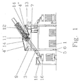
- FIG. 1 shows a view of a handling device for containers 1 consists essentially of a portal frame 2 and a boom 3, the over a swivel drive with hydraulic cylinders 4 is movable.
- the portal frame 2 can be moved on rails 6 on rails 6 and consists of essentially from four vertical beams 7, seen in plan view in the corner points an imaginary rectangle are arranged.
- the ends of the vertical beams 7 are connected on one side to the trolleys 5 and opposite with a frame.
- the frame is made of side members 8, cross members 9 and cross members 10 (s. also Fig. 2) built.
- the axis 11 is in and across Direction of travel of the portal frame 2 seen in the center of the crossbar 10 arranged.
- the boom 3 is designed here as a rigid swivel arm, which in one sleeve-shaped guide element 12 is guided displaceably in its longitudinal direction.
- the boom 3 is thus connected to the axis 11 via the guide element 12.
- the movement of the boom 3 in its longitudinal direction within the Guide element 12 is hydraulic.
- a load suspension device 16 for the container 1 is arranged, which is parallel to the Axis 11 extending further axis 15 pivotally suspended on the boom 3 is.
- the Portal frame 2 has a frame which with the vertical supports 7 (see FIG. 1) is connected and consists of side members 8, cross members 9 and cross members 10.
- the longitudinal beams 8 each connect the ends of the vertical beams 7 (see FIG. 1), seen in the direction of travel of the portal frame 2 one behind the other and from each other are spaced.
- the cross member 9 are each transverse to the direction of travel opposite and spaced vertical beams 7 connected.
- cross members 10 are provided, on which the axis 11 for the boom 3 is stored.
- one per side of the portal frame Pair of hydraulic cylinders 4 is provided for the pivoting movement of the boom 3.
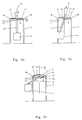
- FIG. 1 is a schematic view of FIG. 1 in show different positions of the boom 3, the operation of the Swivel drive with the hydraulic cylinders 4 explained in more detail.
- the boom 3 is not length-adjustable here and the container 1 and that Load suspension means 16 shown only schematically.
- the hydraulic cylinders 4 are with their Directions of action W in plan view perpendicular to the longitudinal direction L of the boom 3 aligned when this is in its vertical basic position with a Swivel angle a of 0 °.
- the hydraulic cylinders arranged symmetrically to the longitudinal direction L of the boom 3 and their Directions of action W coincide.
- the boom 3 is pivoted to the left only the left hydraulic cylinder 4 'with pressure by a pivoting angle a of about 20 ° pressurized, while the right hydraulic cylinder 4 '' is depressurized and by the left hydraulic cylinder 4 'via the brackets 13 and the boom 3 Piston rod 14 of the right hydraulic cylinder 4 '' is inserted.
- pivot position intersects the effective direction W of the right Hydraulic cylinder 4, the axis 11 of the boom 3.
- the Hydraulic cylinder 4 '' is the piston rod 14 in the furthest retracted position and would then be independent of the Extend the swivel direction of the boom 3 again.
- the hydraulic cylinders 4 are designed so that in the event of a complete failure of one hydraulic cylinder 4 the other hydraulic cylinder 4 den Boom 3 can hold in the respective position when the feed lines are blocked. This hydraulic cylinder 4 can then be braked via an emergency program Ensure movement of boom 3 to the basic position. Uncontrolled This prevents boom movements.
- FIG. 4 is a further schematic view of FIG. 1 Embodiment of the rotary actuator shown.
- This arrangement of the hydraulic cylinder 4 has the advantage that the forces of Hydraulic cylinders 4 ', 4' 'can be optimally introduced into the portal frame 2. In contrast, however, a larger pivot angle a is required until the Hydraulic cylinders 4 ', 4' 'reach their reverse positions.
Landscapes
- Engineering & Computer Science (AREA)
- Mechanical Engineering (AREA)
- Jib Cranes (AREA)
- Forklifts And Lifting Vehicles (AREA)
- Vehicle Cleaning, Maintenance, Repair, Refitting, And Outriggers (AREA)
Abstract
Description
In einer ersten Ausführungsform werden die gegenüberliegenden Hydraulikzylinder mit ihren Wirkrichtungen in der Grundstellung des Auslegers senkrecht zur Längsrichtung des Auslegers ausgerichtet. Hierdurch wird vorteilhafterweise erreicht, daß schon bei sehr geringen Auslenkungen des Auslegers aus der Grundstellung heraus der Umlenkpunkt des einen Hydraulikzylinders erreicht wird.
- Figur 1
- eine Ansicht einer Vorrichtung zum Umschlagen von Containern mit einem Schwenkantrieb über zwei Paare von Hydraulikzylindern,
- Figur 2
- eine Draufsicht von Figur 1,
- Figur 3A bis 3C
- eine schematische Ansicht von Figur 1 mit einer ersten Ausführungsform der Anlenkung der Hydraulikzylinder, mit verschiedenen Schwenkstellungen des Auslegers,
- Figur 4
- eine schematische Ansicht von Figur 1 mit einer weiteren Ausführungsform der Anlenkung der Hydraulikzylinder.
- 1
- Container
- 2
- Portalrahmen
- 3
- Ausleger
- 4', 4''
- Hydraulikzylinder
- 5
- Fahrwerke
- 6
- Schienen
- 7
- Vertikalträger
- 8
- Längsträger
- 9
- Querträger
- 10
- Quertraverse
- 11
- Achse
- 12
- Führungselement
- 13
- Konsole
- 14
- Kolbenstange
- 15
- weitere Achse
- 16
- Lastaufnahmemittel
- a
- Schwenkwinkel
- b
- Abstand
- c
- Abstand
- L
- Längsrichtung
- W
- Wirkrichtung
Claims (16)
- Schwenkantrieb für einen Ausleger einer Hebevorrichtung, insbesondere einer Vorrichtung für den Umschlag von Ladungseinheiten, mit mindestens einem zwischen einem Portalrahmen der Hebevorrichtung und dem an dem Portalrahmen um eine weitestgehend horizontal verlaufende Achse schwenkbar gelagerten Ausleger angeordneten Hydraulikzylinder für eine von einer Grundstellung ausgehenden Schwenkbewegung des Auslegers, an dessen einem Ende ein Lastaufnahmemittel angeordnet ist, wobei der Hydraulikzylinder mit seinem einen Ende an dem Portalrahmen und seinem anderen Ende am Ausleger mit Abstand zur Achse angeordnet ist und eine Wirkrichtung des Hydraulikzylinders in Draufsicht quer zu Achse verläuft,
dadurch gekennzeichnet,
daß mindestens zwei Hydraulikzylinder (4',4'') vorgesehen sind, die derartig beidseitig des Auslegers (3) angeordnet sind, daß in jeder Schwenkstellung des Auslegers (3) mindestens die Wirkrichtung (W) eines Hydraulikzylinders (4',4'') von der Achse (11) beabstandet ist und die Hydraulikzylinder (4',4'') sich jeweils in bezug auf die Achse (11) gesehen gegenüberliegend an dem Portalrahmen (2) abstützen. - Schwenkantrieb nach Anspruch 1,
dadurch gekennzeichnet,
daß die Anordnung der Hydraulikzylinder (4',4'') derart gewählt ist, daß ausgehend von der Grundstellung des Auslegers (3) bei einem geringen Schwenkwinkel (a) und je nach Schwenkrichtung einer der Hydraulikzylinder (4',4'') mit seiner Wirkrichtung (W) die Achse (11) schneidet. - Schwenkantrieb nach Anspruch 2,
dadurch gekennzeichnet,
daß der geringe Schwenkwinkel (a) in einem Bereich von etwa 10° bis 25° liegt. - Schwenkantrieb nach einem der Ansprüche 1 bis 3,
dadurch gekennzeichnet,
daß die Hydraulikzylinder (4',4'') in der Grundstellung des Auslegers (3) symmetrisch zu dem Ausleger (3) ausgerichtet sind. - Schwenkantrieb nach einem der Ansprüche 1 bis 4,
dadurch gekennzeichnet,
daß die Hydraulikzylinder (4',4'') in Grundstellung an dem Ausleger (3) in Längsrichtung (L) des Auslegers (3) mit einem ersten Abstand (b) von der Achse (11) und mit einem zweiten Abstand (c) von der durch die Achse (11) verlaufenden Längsrichtung (L) angelenkt sind und daß das Verhältnis des ersten Abstandes (b) zu dem zweiten Abstand (c) im Bereich zwischen 0,5 und 2,0 liegt. - Schwenkantrieb nach einem der Ansprüche 1 bis 5,
dadurch gekennzeichnet,
daß die Hydraulikzylinder (4',4'') mit ihren Wirkrichtungen (W) in der Grundstellung des Auslegers (3) senkrecht zur Längsrichtung (L) des Auslegers (3) ausgerichtet sind. - Schwenkantrieb nach einem der Ansprüche 1 bis 5,
dadurch gekennzeichnet,
daß die Hydraulikzylinder (4',4'') mit ihren Wirkrichtungen (W) in der Grundstellung des Auslegers (3) winklig zur Längsrichtung (L) des Auslegers (3) ausgerichtet sind und in einer senkrecht zur Längsrichtung (L) des Auslegers (3) verlaufenden und die Achse (11) schneidenden Ebene an dem Portalrahmen (2) angelenkt sind. - Schwenkantrieb nach einem der Ansprüche 1 bis 7,
dadurch gekennzeichnet,
daß die Hydraulikzylinder (4',4'') über ihre Kolbenstangen (14) mit dem Ausleger (3) verbunden sind. - Schwenkantrieb nach einem der Ansprüche 1 bis 8,
dadurch gekennzeichnet,
daß der Ausleger (3) ausgehend von der Grundstellung beidseitig in Schwenkstellungen verschwenkbar ist. - Schwenkantrieb nach Anspruch 9,
dadurch gekennzeichnet
daß der Ausleger (3) in einem Bereich von etwa 0° bis 65° aus der Grundstellung in die jeweilige Schwenkstellung verschwenkbar ist. - Schwenkantrieb nach einem der Ansprüche 1 bis 10,
dadurch gekennzeichnet,
daß der Ausleger (3) in der Grundstellung vertikal ausgerichtet ist. - Schwenkantrieb nach einem der Ansprüche 1 bis 11,
dadurch gekennzeichnet,
daß die Hydraulikzylinder (4',4'') oberhalb der Achse (11) an dem Ausleger (3) angelenkt sind und das Lastaufnahmemittel (16) unterhalb der Achse (11) an dem Ausleger (3) aufgehängt ist. - Schwenkantrieb nach einem der Ansprüche 1 bis 12,
dadurch gekennzeichnet,
daß der Ausleger (3) als starrer Schwenkarm ausgebildet und in einem hülsenförmigen Führungselement (12) in seiner Längsrichtung (L) verschiebbar gelagert ist, das auf dem Portalrahmen (2) schwenkbar gelagert ist. - Schwenkantrieb nach einem der Ansprüche 1 bis 13,
dadurch gekennzeichnet,
daß der Portalrahmen (2) als Fahrrahmen ausgebildet ist, der aus zwei voneinander in dessen Fahrtrichtung und untereinander beabstandeten Paaren von Vertikalträgern (7) mit Fahrwerken (5) gebildet ist, deren den Fahrwerken (5) abgewandte Enden über einem rechteckigen Rahmen verbunden sind, der aus Querträgern (9) und Längsträgern (L) besteht, und in Fahrtrichtung des Portalrahmens (2) gesehen zwischen den Querträgern (9) und parallel hierzu verlaufende Quertraversen (10) mit ihren Enden an den Längsträgern (8) befestigt sind, an denen mittig der Ausleger (3) über die in Fahrtrichtung des Portalrahmens (2) verlaufende Achse (11) gelagert ist. - Schwenkantrieb nach Anspruch 14,
dadurch gekennzeichnet,
daß die Hydraulikzylinder (4',4'') an den Quertraversen (10) des Portalrahmens (2) angelenkt sind. - Verfahren für den Betrieb eines Schwenkantriebes gemäß einem der Ansprüche 1 bis 15,
dadurch gekennzeichnet,
daß ausgehend von der Grundstellung der Ausleger (3) zunächst von dem Hydraulikzylinder (4',4'') verschwenkt wird, der in dieser Schwenkrichtung des Auslegers (3) von der Grundstellung bis zur maximalen Schwenkstellung nur in einer Bewegungsrichtung verfahren wird, durch diese Verschwenkung des Auslegers (3) der andere Hydraulikzylinder (4'',4') im antriebslosen Zustand zunächst eingefahren wird, bis dessen Wirkrichtung (W) die Achse (11) schneidet, anschließend seine Bewegungsrichtung umgekehrt wird und dem ersten Hydraulikzylinder (4',4'') für die Verschwenkung des Auslegers (3) zugeschaltet wird.
Applications Claiming Priority (2)
| Application Number | Priority Date | Filing Date | Title |
|---|---|---|---|
| DE19650834A DE19650834C1 (de) | 1996-11-29 | 1996-11-29 | Schwenkantrieb eines Auslegers einer Hebeeinrichtung und Verfahren zum Betrieb dieses Schwenkantriebes |
| DE19650834 | 1996-11-29 |
Publications (2)
| Publication Number | Publication Date |
|---|---|
| EP0845428A1 true EP0845428A1 (de) | 1998-06-03 |
| EP0845428B1 EP0845428B1 (de) | 2002-08-28 |
Family
ID=7813947
Family Applications (1)
| Application Number | Title | Priority Date | Filing Date |
|---|---|---|---|
| EP97250345A Expired - Lifetime EP0845428B1 (de) | 1996-11-29 | 1997-11-17 | Schwenkantrieb eines Auslegers einer Hebeeinrichtung und Verfahren zum Betrieb dieses Schwenkantriebes |
Country Status (5)
| Country | Link |
|---|---|
| EP (1) | EP0845428B1 (de) |
| AT (1) | ATE222880T1 (de) |
| DE (2) | DE19650834C1 (de) |
| ES (1) | ES2179267T3 (de) |
| PL (1) | PL184222B1 (de) |
Citations (4)
| Publication number | Priority date | Publication date | Assignee | Title |
|---|---|---|---|---|
| DE2545867A1 (de) * | 1975-10-14 | 1976-10-28 | Tuenkers Kg | Pneumatischer oder hydraulischer zylindertrieb mit mehreren doppeltwirkenden antriebszylindern |
| US4078441A (en) * | 1976-02-23 | 1978-03-14 | Harris Corporation | Rotational positioning using linear actuators |
| DE4135182A1 (de) * | 1991-10-24 | 1993-04-29 | Mannesmann Ag | Antriebsvorrichtung |
| DE4437815A1 (de) * | 1994-10-13 | 1996-04-18 | Mannesmann Ag | Vorrichtung zum Güterumschlag von Ladungseinheiten, insbesondere von Containern |
-
1996
- 1996-11-29 DE DE19650834A patent/DE19650834C1/de not_active Expired - Fee Related
-
1997
- 1997-11-17 EP EP97250345A patent/EP0845428B1/de not_active Expired - Lifetime
- 1997-11-17 ES ES97250345T patent/ES2179267T3/es not_active Expired - Lifetime
- 1997-11-17 AT AT97250345T patent/ATE222880T1/de not_active IP Right Cessation
- 1997-11-17 DE DE59708056T patent/DE59708056D1/de not_active Expired - Fee Related
- 1997-11-27 PL PL97323378A patent/PL184222B1/pl unknown
Patent Citations (4)
| Publication number | Priority date | Publication date | Assignee | Title |
|---|---|---|---|---|
| DE2545867A1 (de) * | 1975-10-14 | 1976-10-28 | Tuenkers Kg | Pneumatischer oder hydraulischer zylindertrieb mit mehreren doppeltwirkenden antriebszylindern |
| US4078441A (en) * | 1976-02-23 | 1978-03-14 | Harris Corporation | Rotational positioning using linear actuators |
| DE4135182A1 (de) * | 1991-10-24 | 1993-04-29 | Mannesmann Ag | Antriebsvorrichtung |
| DE4437815A1 (de) * | 1994-10-13 | 1996-04-18 | Mannesmann Ag | Vorrichtung zum Güterumschlag von Ladungseinheiten, insbesondere von Containern |
Also Published As
| Publication number | Publication date |
|---|---|
| DE59708056D1 (de) | 2002-10-02 |
| ATE222880T1 (de) | 2002-09-15 |
| PL184222B1 (pl) | 2002-09-30 |
| EP0845428B1 (de) | 2002-08-28 |
| PL323378A1 (en) | 1998-06-08 |
| ES2179267T3 (es) | 2003-01-16 |
| DE19650834C1 (de) | 1998-04-16 |
Similar Documents
| Publication | Publication Date | Title |
|---|---|---|
| EP0501254B1 (de) | Scherenhubtisch | |
| EP2079607A1 (de) | Flurgebundenes transportfahrzeug, insbesondere für den transport von containern | |
| DE1807061A1 (de) | Fahrzeug zum Handhaben grossvolumiger Behaelter,wie Container | |
| EP1240071B1 (de) | Hebevorrichtung mit einer führung für lasten | |
| DE69429188T2 (de) | Hebevorrichtung zum handhaben eines gleiselements | |
| DE2944289A1 (de) | Hebefahrzeug | |
| EP0590123B1 (de) | Spurbreitenveränderliches fahrwerk | |
| DE4316535A1 (de) | Eisenbahngüterwagen | |
| DE3822542A1 (de) | Ladeanhaenger | |
| DE2146960A1 (de) | Laufkran, Fordergestell od dgl, dessen Untergestell mit gummibereiften Radern versehen ist | |
| DE69302539T2 (de) | Vorrichtung zum Transport volumimöser Teile | |
| DE10047582B4 (de) | Scherenhubtisch | |
| DE19650834C1 (de) | Schwenkantrieb eines Auslegers einer Hebeeinrichtung und Verfahren zum Betrieb dieses Schwenkantriebes | |
| DE1506519B1 (de) | Teleskopausleger | |
| DE69923454T2 (de) | Vorrichtung zur Handhabung von Plattenbündeln und Tragebett zur Anwendung in einer solchen Vorrichtung | |
| DE3910180C2 (de) | ||
| DE3624247C2 (de) | Fahrzeug zum Transport von Betonfertiggaragen | |
| DE69803281T2 (de) | Transportanhänger zum aufheben und bewegen | |
| DE4039768A1 (de) | Zweiwertiges, d.h. zur strassen- und bahnfahrt geeignetes fahrzeug mit mitteln fuer den uebergang von strasse auf bahn und umgekehrt auf beschraenktem raum | |
| DE20016624U1 (de) | Scherenhubtisch | |
| DE2117791C3 (de) | Verfahren und Einrichtung zum Anheben eines Gleises | |
| EP0490094B1 (de) | Zerlegbare Brücke und Fahrzeug zum Verlegen der Brücke | |
| DE3613072C2 (de) | Greifervorrichtung zum lageweisen Erfassen und Umsetzen einer rechteckigen oder quadratischen Kastenschicht | |
| DE29807788U1 (de) | Hubbalken, insbesondere für Einschienenhängebahnen im untertägigen Grubenbetrieb | |
| DE1235805B (de) | Lastfahrzeug mit einer Vorrichtung zum Aufladen von Behaeltern u. dgl. |
Legal Events
| Date | Code | Title | Description |
|---|---|---|---|
| PUAI | Public reference made under article 153(3) epc to a published international application that has entered the european phase |
Free format text: ORIGINAL CODE: 0009012 |
|
| AK | Designated contracting states |
Kind code of ref document: A1 Designated state(s): AT BE CH DE DK ES FI FR GB GR IE IT LI NL PT SE |
|
| AX | Request for extension of the european patent |
Free format text: AL;LT;LV;MK;RO;SI |
|
| 17P | Request for examination filed |
Effective date: 19981130 |
|
| AKX | Designation fees paid |
Free format text: AT BE CH DE DK ES FI FR GB GR IE IT LI NL PT SE |
|
| RBV | Designated contracting states (corrected) |
Designated state(s): AT BE CH DE DK ES FI FR GB GR IE IT LI NL PT SE |
|
| 17Q | First examination report despatched |
Effective date: 20001124 |
|
| GRAG | Despatch of communication of intention to grant |
Free format text: ORIGINAL CODE: EPIDOS AGRA |
|
| GRAG | Despatch of communication of intention to grant |
Free format text: ORIGINAL CODE: EPIDOS AGRA |
|
| GRAH | Despatch of communication of intention to grant a patent |
Free format text: ORIGINAL CODE: EPIDOS IGRA |
|
| RAP1 | Party data changed (applicant data changed or rights of an application transferred) |
Owner name: DEMAG MOBILE CRANES GMBH |
|
| GRAH | Despatch of communication of intention to grant a patent |
Free format text: ORIGINAL CODE: EPIDOS IGRA |
|
| GRAA | (expected) grant |
Free format text: ORIGINAL CODE: 0009210 |
|
| RAP1 | Party data changed (applicant data changed or rights of an application transferred) |
Owner name: DEMAG CRANES & COMPONENTS GMBH |
|
| AK | Designated contracting states |
Kind code of ref document: B1 Designated state(s): AT BE CH DE DK ES FI FR GB GR IE IT LI NL PT SE |
|
| PG25 | Lapsed in a contracting state [announced via postgrant information from national office to epo] |
Ref country code: IE Free format text: LAPSE BECAUSE OF FAILURE TO SUBMIT A TRANSLATION OF THE DESCRIPTION OR TO PAY THE FEE WITHIN THE PRESCRIBED TIME-LIMIT Effective date: 20020828 Ref country code: GR Free format text: LAPSE BECAUSE OF FAILURE TO SUBMIT A TRANSLATION OF THE DESCRIPTION OR TO PAY THE FEE WITHIN THE PRESCRIBED TIME-LIMIT Effective date: 20020828 Ref country code: FI Free format text: LAPSE BECAUSE OF FAILURE TO SUBMIT A TRANSLATION OF THE DESCRIPTION OR TO PAY THE FEE WITHIN THE PRESCRIBED TIME-LIMIT Effective date: 20020828 |
|
| REF | Corresponds to: |
Ref document number: 222880 Country of ref document: AT Date of ref document: 20020915 Kind code of ref document: T |
|
| REG | Reference to a national code |
Ref country code: GB Ref legal event code: FG4D Free format text: NOT ENGLISH |
|
| REG | Reference to a national code |
Ref country code: CH Ref legal event code: EP |
|
| REF | Corresponds to: |
Ref document number: 59708056 Country of ref document: DE Date of ref document: 20021002 |
|
| REG | Reference to a national code |
Ref country code: IE Ref legal event code: FG4D Free format text: GERMAN |
|
| PGFP | Annual fee paid to national office [announced via postgrant information from national office to epo] |
Ref country code: IE Payment date: 20021104 Year of fee payment: 6 |
|
| PG25 | Lapsed in a contracting state [announced via postgrant information from national office to epo] |
Ref country code: AT Free format text: LAPSE BECAUSE OF NON-PAYMENT OF DUE FEES Effective date: 20021117 |
|
| ET | Fr: translation filed | ||
| PG25 | Lapsed in a contracting state [announced via postgrant information from national office to epo] |
Ref country code: SE Free format text: LAPSE BECAUSE OF FAILURE TO SUBMIT A TRANSLATION OF THE DESCRIPTION OR TO PAY THE FEE WITHIN THE PRESCRIBED TIME-LIMIT Effective date: 20021128 Ref country code: DK Free format text: LAPSE BECAUSE OF FAILURE TO SUBMIT A TRANSLATION OF THE DESCRIPTION OR TO PAY THE FEE WITHIN THE PRESCRIBED TIME-LIMIT Effective date: 20021128 |
|
| PG25 | Lapsed in a contracting state [announced via postgrant information from national office to epo] |
Ref country code: LI Free format text: LAPSE BECAUSE OF NON-PAYMENT OF DUE FEES Effective date: 20021130 Ref country code: CH Free format text: LAPSE BECAUSE OF NON-PAYMENT OF DUE FEES Effective date: 20021130 Ref country code: BE Free format text: LAPSE BECAUSE OF NON-PAYMENT OF DUE FEES Effective date: 20021130 |
|
| PG25 | Lapsed in a contracting state [announced via postgrant information from national office to epo] |
Ref country code: PT Free format text: LAPSE BECAUSE OF FAILURE TO SUBMIT A TRANSLATION OF THE DESCRIPTION OR TO PAY THE FEE WITHIN THE PRESCRIBED TIME-LIMIT Effective date: 20021210 |
|
| GBT | Gb: translation of ep patent filed (gb section 77(6)(a)/1977) |
Effective date: 20021129 |
|
| REG | Reference to a national code |
Ref country code: ES Ref legal event code: FG2A Ref document number: 2179267 Country of ref document: ES Kind code of ref document: T3 |
|
| BERE | Be: lapsed |
Owner name: *DEMAG CRANES & COMPONENTS G.M.B.H. Effective date: 20021130 |
|
| PLBE | No opposition filed within time limit |
Free format text: ORIGINAL CODE: 0009261 |
|
| STAA | Information on the status of an ep patent application or granted ep patent |
Free format text: STATUS: NO OPPOSITION FILED WITHIN TIME LIMIT |
|
| REG | Reference to a national code |
Ref country code: CH Ref legal event code: PL |
|
| REG | Reference to a national code |
Ref country code: IE Ref legal event code: FD4D Ref document number: 0845428E Country of ref document: IE |
|
| 26N | No opposition filed |
Effective date: 20030530 |
|
| PGFP | Annual fee paid to national office [announced via postgrant information from national office to epo] |
Ref country code: GB Payment date: 20031029 Year of fee payment: 7 |
|
| PGFP | Annual fee paid to national office [announced via postgrant information from national office to epo] |
Ref country code: NL Payment date: 20031030 Year of fee payment: 7 |
|
| PGFP | Annual fee paid to national office [announced via postgrant information from national office to epo] |
Ref country code: DE Payment date: 20031103 Year of fee payment: 7 |
|
| PGFP | Annual fee paid to national office [announced via postgrant information from national office to epo] |
Ref country code: FR Payment date: 20031107 Year of fee payment: 7 |
|
| PGFP | Annual fee paid to national office [announced via postgrant information from national office to epo] |
Ref country code: ES Payment date: 20031120 Year of fee payment: 7 |
|
| PG25 | Lapsed in a contracting state [announced via postgrant information from national office to epo] |
Ref country code: GB Free format text: LAPSE BECAUSE OF NON-PAYMENT OF DUE FEES Effective date: 20041117 |
|
| PG25 | Lapsed in a contracting state [announced via postgrant information from national office to epo] |
Ref country code: ES Free format text: LAPSE BECAUSE OF NON-PAYMENT OF DUE FEES Effective date: 20041118 |
|
| PG25 | Lapsed in a contracting state [announced via postgrant information from national office to epo] |
Ref country code: NL Free format text: LAPSE BECAUSE OF NON-PAYMENT OF DUE FEES Effective date: 20050601 Ref country code: DE Free format text: LAPSE BECAUSE OF NON-PAYMENT OF DUE FEES Effective date: 20050601 |
|
| GBPC | Gb: european patent ceased through non-payment of renewal fee |
Effective date: 20041117 |
|
| PG25 | Lapsed in a contracting state [announced via postgrant information from national office to epo] |
Ref country code: FR Free format text: LAPSE BECAUSE OF NON-PAYMENT OF DUE FEES Effective date: 20050729 |
|
| NLV4 | Nl: lapsed or anulled due to non-payment of the annual fee |
Effective date: 20050601 |
|
| REG | Reference to a national code |
Ref country code: FR Ref legal event code: ST |
|
| PG25 | Lapsed in a contracting state [announced via postgrant information from national office to epo] |
Ref country code: IT Free format text: LAPSE BECAUSE OF NON-PAYMENT OF DUE FEES;WARNING: LAPSES OF ITALIAN PATENTS WITH EFFECTIVE DATE BEFORE 2007 MAY HAVE OCCURRED AT ANY TIME BEFORE 2007. THE CORRECT EFFECTIVE DATE MAY BE DIFFERENT FROM THE ONE RECORDED. Effective date: 20051117 |
|
| REG | Reference to a national code |
Ref country code: ES Ref legal event code: FD2A Effective date: 20041118 |