EP0845560A1 - Bedienungsvorrichtung für eine Spüleinrichtung - Google Patents
Bedienungsvorrichtung für eine Spüleinrichtung Download PDFInfo
- Publication number
- EP0845560A1 EP0845560A1 EP97203709A EP97203709A EP0845560A1 EP 0845560 A1 EP0845560 A1 EP 0845560A1 EP 97203709 A EP97203709 A EP 97203709A EP 97203709 A EP97203709 A EP 97203709A EP 0845560 A1 EP0845560 A1 EP 0845560A1
- Authority
- EP
- European Patent Office
- Prior art keywords
- operating
- operating device
- flushing
- transmission element
- installation
- Prior art date
- Legal status (The legal status is an assumption and is not a legal conclusion. Google has not performed a legal analysis and makes no representation as to the accuracy of the status listed.)
- Withdrawn
Links
Images
Classifications
-
- E—FIXED CONSTRUCTIONS
- E03—WATER SUPPLY; SEWERAGE
- E03D—WATER-CLOSETS OR URINALS WITH FLUSHING DEVICES; FLUSHING VALVES THEREFOR
- E03D1/00—Water flushing devices with cisterns ; Setting up a range of flushing devices or water-closets; Combinations of several flushing devices
- E03D1/01—Shape or selection of material for flushing cisterns
- E03D1/012—Details of shape of cisterns, e.g. for connecting to wall, for supporting or connecting flushing-device actuators
-
- E—FIXED CONSTRUCTIONS
- E03—WATER SUPPLY; SEWERAGE
- E03D—WATER-CLOSETS OR URINALS WITH FLUSHING DEVICES; FLUSHING VALVES THEREFOR
- E03D1/00—Water flushing devices with cisterns ; Setting up a range of flushing devices or water-closets; Combinations of several flushing devices
- E03D1/02—High-level flushing systems
- E03D1/14—Cisterns discharging variable quantities of water also cisterns with bell siphons in combination with flushing valves
- E03D1/142—Cisterns discharging variable quantities of water also cisterns with bell siphons in combination with flushing valves in cisterns with flushing valves
- E03D1/144—Cisterns discharging variable quantities of water also cisterns with bell siphons in combination with flushing valves in cisterns with flushing valves having a single flush outlet and an additional float for delaying the valve closure
-
- E—FIXED CONSTRUCTIONS
- E03—WATER SUPPLY; SEWERAGE
- E03D—WATER-CLOSETS OR URINALS WITH FLUSHING DEVICES; FLUSHING VALVES THEREFOR
- E03D5/00—Special constructions of flushing devices, e.g. closed flushing system
- E03D5/02—Special constructions of flushing devices, e.g. closed flushing system operated mechanically or hydraulically (or pneumatically) also details such as push buttons, levers and pull-card therefor
- E03D5/028—Pusher plates and actuating mechanisms for built-in cisterns
-
- E—FIXED CONSTRUCTIONS
- E03—WATER SUPPLY; SEWERAGE
- E03D—WATER-CLOSETS OR URINALS WITH FLUSHING DEVICES; FLUSHING VALVES THEREFOR
- E03D5/00—Special constructions of flushing devices, e.g. closed flushing system
- E03D5/02—Special constructions of flushing devices, e.g. closed flushing system operated mechanically or hydraulically (or pneumatically) also details such as push buttons, levers and pull-card therefor
- E03D5/09—Special constructions of flushing devices, e.g. closed flushing system operated mechanically or hydraulically (or pneumatically) also details such as push buttons, levers and pull-card therefor directly by the hand
Definitions
- the invention relates to an operating device for a flushing installation, which can deliver a plurality of different flushing volumes.
- Flushing of a water closet contributes significantly to the water consumption of an average household. Since the supply of sufficient water for consumptive as well as other domestic use has required increased effort in recent years and the cost of water supply is rising ever more sharply, attempts are being made to reduce the water consumption per household. A search has therefore already been underway for a long time for water closets which have a lower water consumption per flush than conventional water closets. This has resulted inter alia in the advent of water closets with flush interruption, wherein a user can discontinue flushing once it has initiated by repeated operation of a control button or lever, whereby a valve in the flushing installation is returned more quickly to its closing position.
- Flushing installations have therefore already been proposed whereby two separate flushing operations can be performed, wherein different quantities of flushing water are delivered.
- An example of such a flushing installation which is designated in practice as a flushing installation for a full or half flush, is for instance known from applicant's earlier patent application EP-A-0 727 533.
- the flushing installation is herein embodied as a so-called close-coupled toilet suite, wherein a cistern is fixed onto the toilet bowl at the rear.
- Two push buttons are herein arranged in the upper wall of the cistern for operation of the flushing installation.
- the present invention therefore has for its object to provide an operating device for a flushing installation with a plurality of different flushing volumes, whereby it becomes possible to apply such a flushing installation in combination with a wall-mounted toilet.
- the operating device is provided with at least one lying transmission element connected to lifting means of the flushing installation, and at least two elements connected to the or each transmission element for operation thereof with a different stroke.
- the invention further relates to a flushing installation provided with an operating device as described above.
- a flushing installation is preferably placed behind a wall on which the operating device is arranged.
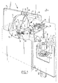
- the transmission element 4 is in turn connected to two separate operating elements 5L, 5R, which have different strokes S L , S R .
- These operating elements 5L, 5R are pivotable on a horizontal shaft 6 and have a part 7 situated above shaft 6 which forms the actual operating part, while each operating element 5 is connected under shaft 6 to transmission element 4 by a connection 10.
- Transmission element 4 is herein a pulling element which is connected to lifting tube 3 via a lever mechanism 27 to be described hereinbelow.
- the operating elements 5 are received in or connected to an operating panel 16, which has an arcuate opening 15 in which the semi-arcuate operating elements 5 are arranged.
- Operating panel 16 is in turn fixed to a mounting edge 17, for instance by means of a snap connection, which edge is arranged round an opening 18 in a wall 14 behind which flushing installation 2 is concealed.
- Both operating elements 5L, 5R co-act with a collective stepped stop 8 which is connected to mounting edge 17 and which has a relatively short leg 8L and a longer leg 8R.
- the pivoting movement of the parts 7 of operating elements 5L, 5R are thus bounded by the legs 8L, 8R of stop 8.
- the operating elements 5L, 5R each have a different stroke S L , S R .
- Operating elements 5L, 5R are each connected to spring means 9, whereby they are urged back to their starting position after they have been operated.
- These spring means 9 herein take the form in each case of a torsion spring which is wound round pivot shaft 6 and which engages with one leg on a connection part 21 of operating panel 16 running through behind operating elements 5L, 5R and which engages with its other leg on operating elements 5L, 5R.
- Pivot shaft 6 is herein mounted in sleeves 20 arranged on connecting wall 21, while operating elements 5L, 5R are connected to pivot shaft 6 by means of ears 19 engaging round shaft 6.
- connection 10 between operating elements 5L, 5R and transmission element 4 has a clearance corresponding with the larger stroke S L or S R which operating elements 5L, 5R can make.
- connection 10 is formed for this purpose by two hook-shaped members 12L, 12R which protrude to the rear from operating elements 5R and which co-act with a T-shaped end part 11 of transmission element 4.
- Each hook-shaped connecting member 12L, 12R herein co-acts with one of the legs 13L, 13R of T-shaped end part 11 (fig. 2). If one of the operating elements, in the shown example the left-hand operating element 5L, is now operated by pushing the upper operating part 7 into the wall, the part thereof lying beneath pivot shaft 6 will then move forward from the wall 14 as according to the arrow A, whereby the T-shaped end part 11 is pulled along therewith. This movement is bounded when the upper part 7 of operating element 5L contacts the leg 8L of stop 8.
- the T-shaped end part 11, and therewith transmission element 4 has then been pulled outward through a stroke S L .
- the length over which hook-shaped member 12R herein protrudes from the right-hand operating element 5R must of course be at least as great as the stroke S L in order to prevent T-shaped end part 11 hereby being inhibited in its movement.
- operating element 5L When operating element 5L is subsequently released, it is urged back to its starting position by spring 9, so that the left-hand hook-shaped member 12L must also protrude from operating element 5L over at least the stroke length S L in order to prevent the T-shaped end part 11 being pressed inward again by this return to the starting position.
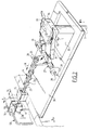
- the T-shaped end part 11 is connected to transmission element 4 which is mounted slidably in a bearing 22.
- Transmission element 4 is in turn connected to lifting tube 3 of flushing installation 2 via a knee lever 27.
- the transmission element 4 is constructed from a rod-like part 23 with a plurality of spacing rings 24 formed integrally therewith, with which the transmission element 4 can be snapped fixedly into a slot 25 of an arm 26 of lever 27.
- Lever 27 is herein pivotable on a shaft 28 which is received in bearing blocks 29 fixed on a plate 30 protruding above the cistern 36.
- the lying arm 31 of knee lever 27 takes a divided form, wherein the parts 31 are each provided with mutually facing pins 32 which can be hooked into a slot 33 of a cover 34 connected to flushing tube 3.
- the transmission element 4 By operating one of the operating elements 5L or 5R the transmission element 4 is thus pulled in the direction of the arrow M, whereby knee lever 27 pivots in the direction of arrows P and the lifting tube 3 of flushing installation 2 is raised as according to arrow L.
- a valve 40 connected to lifting tube 3 is thereby moved clear of an outflow opening 41 in the underside of cistern 36, so that the water 37 can run as according to arrow F out of cistern 36 into a discharge tube 38 leading to the toilet bowl.
- the valve 40 is further held up by the float elements 39 which are connected to flush tube 3 and which float in the water 37 in cistern 36.
- the quantity of water which finally leaves cistern 36 per flush is therefore determined solely by the distance over which flush tube 3 is carried upward, this distance being determined in turn by the stroke of the operating element 5L or 5R.
- the user can thus opt for a full or half flush simply by depressing one of the two operating elements 5L or 5R, without extra operations being required for this purpose, as in the case of a flush interruption. It is anticipated that in practice more users will hereby opt for a half flush, whereby the total water consumption of the flushing installation is reduced.
Landscapes
- Engineering & Computer Science (AREA)
- Health & Medical Sciences (AREA)
- Life Sciences & Earth Sciences (AREA)
- Hydrology & Water Resources (AREA)
- Public Health (AREA)
- Water Supply & Treatment (AREA)
- Mechanical Engineering (AREA)
- Aviation & Aerospace Engineering (AREA)
- Sanitary Device For Flush Toilet (AREA)
Applications Claiming Priority (2)
| Application Number | Priority Date | Filing Date | Title |
|---|---|---|---|
| NL1004653A NL1004653C2 (nl) | 1996-11-29 | 1996-11-29 | Bedieningsinrichting voor een spoelinstallatie. |
| NL1004653 | 1996-11-29 |
Publications (1)
| Publication Number | Publication Date |
|---|---|
| EP0845560A1 true EP0845560A1 (de) | 1998-06-03 |
Family
ID=19763959
Family Applications (1)
| Application Number | Title | Priority Date | Filing Date |
|---|---|---|---|
| EP97203709A Withdrawn EP0845560A1 (de) | 1996-11-29 | 1997-11-27 | Bedienungsvorrichtung für eine Spüleinrichtung |
Country Status (2)
| Country | Link |
|---|---|
| EP (1) | EP0845560A1 (de) |
| NL (1) | NL1004653C2 (de) |
Cited By (3)
| Publication number | Priority date | Publication date | Assignee | Title |
|---|---|---|---|---|
| EP1088942A3 (de) * | 1999-09-28 | 2003-01-02 | Franz Viegener II GmbH & Co. KG. | Betätigungseinrichtung |
| NL2005519C2 (nl) * | 2010-10-14 | 2012-04-17 | Easy Sanitairy Solutions Bv | Combinatie van een spoelreservoir voor een toilet, een wand aangebracht voor het spoelreservoir en een bedieningselement voor het bedienen van het spoelreservoir. |
| EP1593787B1 (de) * | 2004-05-05 | 2016-05-18 | Ifö Sanitär AB | Spülmechanismus für eine Toilette |
Citations (4)
| Publication number | Priority date | Publication date | Assignee | Title |
|---|---|---|---|---|
| LU83666A1 (de) * | 1980-12-15 | 1982-02-18 | Geberit Ag | Betaetigungsvorrichtung fuer das ablaufventil eines unterputz-spuelkastens |
| EP0727533A2 (de) * | 1995-02-17 | 1996-08-21 | Wisa B.V. | Zweimengentoilettenspülvorrichtung |
| DE19508865A1 (de) * | 1995-03-11 | 1996-09-12 | Schwab Sanitaer Plastic Gmbh | Halterung für Betätigungsorgane eines Spülkastens |
| EP0733749A1 (de) * | 1995-03-23 | 1996-09-25 | Friatec Aktiengesellschaft Keramik- und Kunststoffwerke | Betätigungsvorrichtung für eine Ablaufarmatur eines Spülkastens |
-
1996
- 1996-11-29 NL NL1004653A patent/NL1004653C2/nl not_active IP Right Cessation
-
1997
- 1997-11-27 EP EP97203709A patent/EP0845560A1/de not_active Withdrawn
Patent Citations (4)
| Publication number | Priority date | Publication date | Assignee | Title |
|---|---|---|---|---|
| LU83666A1 (de) * | 1980-12-15 | 1982-02-18 | Geberit Ag | Betaetigungsvorrichtung fuer das ablaufventil eines unterputz-spuelkastens |
| EP0727533A2 (de) * | 1995-02-17 | 1996-08-21 | Wisa B.V. | Zweimengentoilettenspülvorrichtung |
| DE19508865A1 (de) * | 1995-03-11 | 1996-09-12 | Schwab Sanitaer Plastic Gmbh | Halterung für Betätigungsorgane eines Spülkastens |
| EP0733749A1 (de) * | 1995-03-23 | 1996-09-25 | Friatec Aktiengesellschaft Keramik- und Kunststoffwerke | Betätigungsvorrichtung für eine Ablaufarmatur eines Spülkastens |
Cited By (4)
| Publication number | Priority date | Publication date | Assignee | Title |
|---|---|---|---|---|
| EP1088942A3 (de) * | 1999-09-28 | 2003-01-02 | Franz Viegener II GmbH & Co. KG. | Betätigungseinrichtung |
| EP1593787B1 (de) * | 2004-05-05 | 2016-05-18 | Ifö Sanitär AB | Spülmechanismus für eine Toilette |
| NL2005519C2 (nl) * | 2010-10-14 | 2012-04-17 | Easy Sanitairy Solutions Bv | Combinatie van een spoelreservoir voor een toilet, een wand aangebracht voor het spoelreservoir en een bedieningselement voor het bedienen van het spoelreservoir. |
| EP2441895A1 (de) * | 2010-10-14 | 2012-04-18 | Easy Sanitairy Solutions B.V. | Kombination von Spülkasten, Wand und Spültaste, wobei die Wand vor dem Spülkasten montiert ist |
Also Published As
| Publication number | Publication date |
|---|---|
| NL1004653C2 (nl) | 1998-06-03 |
Similar Documents
| Publication | Publication Date | Title |
|---|---|---|
| US4485501A (en) | Water saving flush tank mechanism | |
| EP0268381B1 (de) | Zweimengen-Spülkastenmechanismus | |
| US4750219A (en) | Urinal device | |
| US5715543A (en) | Toilet assembly having an automatic ventilation system | |
| WO1981000734A1 (en) | Variable volume control for toilet flush tanks | |
| US5167039A (en) | Toilet assembly | |
| US5524297A (en) | Two-level flush valve | |
| US3120006A (en) | Toilet bowl and bathroom ventilating system | |
| AU2014344787A1 (en) | Water saving toilet system | |
| EP0727533A2 (de) | Zweimengentoilettenspülvorrichtung | |
| JP3225285B2 (ja) | 遠隔操作式の排水栓開閉装置 | |
| US7975322B1 (en) | Foot pedal toilet flush device | |
| US4240168A (en) | Combination commode construction | |
| KR100499662B1 (ko) | 절수가 가능한 변기 | |
| US3947900A (en) | Combination commode construction | |
| NL1004653C2 (nl) | Bedieningsinrichting voor een spoelinstallatie. | |
| US5829067A (en) | Toilet seat lift assembly | |
| GB2370586A (en) | Flush toilet with moveable trap | |
| KR200457162Y1 (ko) | 대변 및 소변에 따라 물내림양을 조절할 수 있는 좌변식 변기용 플러시밸브 구조 | |
| GB2396163A (en) | Toilet cistern valve assembly | |
| US4086667A (en) | Flush control device for conserving water | |
| EP0733138A1 (de) | Toilettenmöbel | |
| CN220908578U (zh) | 出水组件及坐便器 | |
| PL349803A1 (en) | Quick-discharge valve control device for lavatory bowl flushing cisterns | |
| US20020124302A1 (en) | Flush toilets |
Legal Events
| Date | Code | Title | Description |
|---|---|---|---|
| PUAI | Public reference made under article 153(3) epc to a published international application that has entered the european phase |
Free format text: ORIGINAL CODE: 0009012 |
|
| AK | Designated contracting states |
Kind code of ref document: A1 Designated state(s): AT BE CH DE DK ES FI FR GB GR IE IT LI LU MC NL PT SE |
|
| AX | Request for extension of the european patent |
Free format text: AL;LT;LV;MK;RO;SI |
|
| 17P | Request for examination filed |
Effective date: 19981203 |
|
| AKX | Designation fees paid |
Free format text: AT BE CH DE DK ES FI FR GB GR IE IT LI LU MC NL PT SE |
|
| RBV | Designated contracting states (corrected) |
Designated state(s): AT BE CH DE DK ES FI FR GB GR IE IT LI LU MC NL PT SE |
|
| 17Q | First examination report despatched |
Effective date: 20010723 |
|
| GRAP | Despatch of communication of intention to grant a patent |
Free format text: ORIGINAL CODE: EPIDOSNIGR1 |
|
| STAA | Information on the status of an ep patent application or granted ep patent |
Free format text: STATUS: THE APPLICATION IS DEEMED TO BE WITHDRAWN |
|
| 18D | Application deemed to be withdrawn |
Effective date: 20040127 |