EP0845568A2 - Aushängbares Türscharnier für Kraftwagentüren - Google Patents
Aushängbares Türscharnier für Kraftwagentüren Download PDFInfo
- Publication number
- EP0845568A2 EP0845568A2 EP97119297A EP97119297A EP0845568A2 EP 0845568 A2 EP0845568 A2 EP 0845568A2 EP 97119297 A EP97119297 A EP 97119297A EP 97119297 A EP97119297 A EP 97119297A EP 0845568 A2 EP0845568 A2 EP 0845568A2
- Authority
- EP
- European Patent Office
- Prior art keywords
- hinge
- profile
- door
- eyes
- halves
- Prior art date
- Legal status (The legal status is an assumption and is not a legal conclusion. Google has not performed a legal analysis and makes no representation as to the accuracy of the status listed.)
- Granted
Links
Images

Classifications
-
- E—FIXED CONSTRUCTIONS
- E05—LOCKS; KEYS; WINDOW OR DOOR FITTINGS; SAFES
- E05D—HINGES OR SUSPENSION DEVICES FOR DOORS, WINDOWS OR WINGS
- E05D7/00—Hinges or pivots of special construction
- E05D7/10—Hinges or pivots of special construction to allow easy separation or connection of the parts at the hinge axis
- E05D7/1044—Hinges or pivots of special construction to allow easy separation or connection of the parts at the hinge axis in an axial direction
- E05D7/105—Hinges or pivots of special construction to allow easy separation or connection of the parts at the hinge axis in an axial direction requiring a specific angular position
-
- E—FIXED CONSTRUCTIONS
- E05—LOCKS; KEYS; WINDOW OR DOOR FITTINGS; SAFES
- E05D—HINGES OR SUSPENSION DEVICES FOR DOORS, WINDOWS OR WINGS
- E05D11/00—Additional features or accessories of hinges
- E05D11/10—Devices for preventing movement between relatively-movable hinge parts
- E05D11/1028—Devices for preventing movement between relatively-movable hinge parts for maintaining the hinge in two or more positions, e.g. intermediate or fully open
- E05D11/1078—Devices for preventing movement between relatively-movable hinge parts for maintaining the hinge in two or more positions, e.g. intermediate or fully open the maintaining means acting parallel to the pivot
- E05D11/1085—Devices for preventing movement between relatively-movable hinge parts for maintaining the hinge in two or more positions, e.g. intermediate or fully open the maintaining means acting parallel to the pivot specially adapted for vehicles
-
- E—FIXED CONSTRUCTIONS
- E05—LOCKS; KEYS; WINDOW OR DOOR FITTINGS; SAFES
- E05D—HINGES OR SUSPENSION DEVICES FOR DOORS, WINDOWS OR WINGS
- E05D5/00—Construction of single parts, e.g. the parts for attachment
- E05D5/02—Parts for attachment, e.g. flaps
- E05D5/06—Bent flaps
- E05D5/062—Bent flaps specially adapted for vehicles
-
- E—FIXED CONSTRUCTIONS
- E05—LOCKS; KEYS; WINDOW OR DOOR FITTINGS; SAFES
- E05D—HINGES OR SUSPENSION DEVICES FOR DOORS, WINDOWS OR WINGS
- E05D5/00—Construction of single parts, e.g. the parts for attachment
- E05D5/10—Pins, sockets or sleeves; Removable pins
- E05D5/12—Securing pins in sockets, movably or not
- E05D5/128—Securing pins in sockets, movably or not the pin having a recess or through-hole engaged by a securing member
-
- E—FIXED CONSTRUCTIONS
- E05—LOCKS; KEYS; WINDOW OR DOOR FITTINGS; SAFES
- E05D—HINGES OR SUSPENSION DEVICES FOR DOORS, WINDOWS OR WINGS
- E05D7/00—Hinges or pivots of special construction
- E05D7/12—Hinges or pivots of special construction to allow easy detachment of the hinge from the wing or the frame
- E05D7/121—Hinges or pivots of special construction to allow easy detachment of the hinge from the wing or the frame specially adapted for vehicles
-
- E—FIXED CONSTRUCTIONS
- E05—LOCKS; KEYS; WINDOW OR DOOR FITTINGS; SAFES
- E05Y—INDEXING SCHEME ASSOCIATED WITH SUBCLASSES E05D AND E05F, RELATING TO CONSTRUCTION ELEMENTS, ELECTRIC CONTROL, POWER SUPPLY, POWER SIGNAL OR TRANSMISSION, USER INTERFACES, MOUNTING OR COUPLING, DETAILS, ACCESSORIES, AUXILIARY OPERATIONS NOT OTHERWISE PROVIDED FOR, APPLICATION THEREOF
- E05Y2900/00—Application of doors, windows, wings or fittings thereof
- E05Y2900/50—Application of doors, windows, wings or fittings thereof for vehicles
- E05Y2900/53—Type of wing
- E05Y2900/531—Doors
Definitions
- the invention relates to a detachable door hinge for motor vehicle doors, consisting of two each on a door arrangement part, door or door pillar , attachable hinge halves, each two at a distance from each other arranged hinge eyes aligned with each other, and two hinge pin stubs, each in one of the two hinge eyes one hinge half is fixed and with the hinge hooked into the complementary hinge eye of the other hinge half engages, at projections and recesses are provided alternately on both hinge halves are, which with the hinge attached, at least over its operating pivot angle interlock and secure against accidental Unhinge the hinge.
- Detachable motor vehicle door hinges of this type are known per se, e.g. from DE-OS 36 44 576.
- This known type of such by the Replacement of a continuous hinge pin with two hinge pin stubs characterized car door hinge mainly has one greatest possible reduction in the height of the hinge, i.e. the lifting height, which is necessary to separate the two hinge halves from each other.
- the two hinge halves exist at least in terms of one of the two hinge halves from a length section of one massive hinge profile, resulting in particular at a greater distance between hinge axis and hinge stop surface on the one hand a relative high weight of the hinge results and secondly at least with regard to the hinge half formed from a solid hinge profile a relatively high processing and thus manufacturing effort results.
- the known types of such designed are detachable Motor vehicle door hinges usually resulting from e.g. by means of an additional existing door lock limiting the maximum permitted opening angle of the vehicle door with one at in provide the vehicle with a built-in hinge effective safety catch, during transport between the hinge production site and its installation location is not secured against falling apart. In many Cases is also a way to lock the hinge in one Partially opened door position appropriate to the initial installation to facilitate the door.
- the invention has for its object hinged door hinge for To improve motor vehicle doors so that even when using hinge wings formed by pressed sheet metal parts form-fitting against an unintentional Unhooking secured and with as little effort as possible can be removed and attached, both securing against accidental Unhooking the two hinge halves during transport, i.e. before installing the hinge, as well as a lockable lock of the two hinge halves in a door corresponding to a partially opened one Position must be guaranteed.
- This object is essentially achieved in that the two hinge halves each by a folded sheet material blank are formed and at least in the area of the hinge axis a U-shaped Have profile cross-sectional shape and that the hinge eyes in the profile legs the U-shaped profile cross-sectional shape of the two hinge halves are arranged and that the two hinge halves also a device for mutual locking of the two hinge halves both in one of the closed as well as in a further the partially open position of the Door is assigned corresponding pivot position.
- the two hinge halves overlap each other with their profile base, arranged such that the one profile leg of the one hinge half engages between the two profile legs of the other hinge half.
- the Hinge pin stubs are expediently in the hinge eyes of the overlapping hinge half and grip when assembled Hinge into the hinge eyes of the overlapped hinge half a.
- the profile legs of the two hinge halves are designed that they mutually over the entire possible swivel range of the Overlap the hinge.
- the safety catch of the installed in the vehicle Hinge is made possible according to the invention in that Profile base of the overlapped hinge half one parallel to the one Profile leg aligned and adjacent to this slot recess cut out for the assigned profile leg of the overlapping hinge half is.
- the length of the slot recess is dimensioned so that the Profile leg of the overlapping hinge half at least in one of the Hinge half of the vehicle door corresponding to the closed position is engaged.
- the hinge For attaching and detaching the hinge is further provided that in the profile bottom of the overlapped hinge half to the Adjacent slot recess, one over in the direction of the hinge axis one of the axial length of the hinge eye of the overlapping hinge half projecting part of the hinge pin corresponding width extending Extension of the slot recess is arranged.
- the one or Unhooking the hinge is only in a partial opening position of the door appropriate position of the two hinge halves possible.
- the next step is then provided that the profile legs having the hinge eyes of the overlapping Hinge half only a larger one in the area of the hinge eyes Have height over the remaining length range of the overlapping Half of the hinge, however, only as an edge rest of the base of the profile are trained.
- the profile leg In the longitudinal direction of the profile leg there is a larger one Dimension the area so that it is in the closed position Vehicle door with the slot recess in the base of the overlapped profile Hinge half is engaged.
- the attacked Half of the hinge is cut free a projection directed radially to the hinge axis and at the same time it is provided that the profile reason of the overarching Hinge half at its end adjacent to the hinge eyes against the Hinge axis is angled.
- Detent spring is arranged, which is formed from a spring sheet blank and pivotable on the outside about an axis concentric to the hinge axis of the profile leg mounted and with each other with respect to the hinge axis
- Opposing arms is equipped, with one arm one in has essentially trapezoidal plan shape, in the end region two spaced apart, concentric along one to the axis of the hinge eye Circular path trained detent projections and their other Arm is shaped into a holding nose in its end region.
- the one about her with spaced detent projections equipped in Floor plan roughly trapezoidal arm in two different pivot positions against one hinge half lockable and over her other arm detent spring that interacts positively with the other hinge half enables a mutual in their one, in particular first, latching position Locking or fixing both hinge halves in one of the closed Doors corresponding position and in their other, especially second Rest position a mutual locking or finding of the two Hinge halves in a position corresponding to the partially open door.
- the detent spring is in one Way rotatably connected that against the final assembly of the vehicle door a correspondingly designed clip is interchangeable.
- the detent spring is pivotable either in Hinge eye, for example by means of one engaging in the hinge eye Collar or the like. Stored or clipped onto the sachet stub is.
- the two spaced detent projections in the inner arm of the detent spring is assigned a detent recess in the flank surface of the detent spring carrying the leg of the overlapped hinge half.
- the locking lug of the detent spring which in its at least one latched pivot position cooperates with the hinge-eye-side string end of the overlapping hinge half, is formed on an angled portion of the other side of the detent spring encompassing the end face of the overlapping hinge half and is oriented essentially parallel to the plane of the profile leg of the overlapped hinge half.
- the locking projections on one, inner arm of the locking spring are arranged so that the other formed on the other, cooperating with the overlapping hinge arm retaining tab cancels the pivoting mobility of the overlapping hinge half and that in the closed position of the door corresponding position of the overlapping hinge half.
- Motor vehicle door hinge can also be provided that profile base and / or profile leg at least the overlapped hinge half on her the ends facing away from the hinge eyes are at right angles to their ends Longitudinal parked and in the area of their parking with inward directional embossments forming bead-like stiffeners are.
- the bead-like embossments are in an expedient arrangement each arranged in the area of the center of the respective rack and only extend beyond the bend.
- the two hinge pins each forming a hinge pin stub can be formed by head bolts and in the hinge eyes of the overlapping Hinge half, for example by means of a peripheral knurl or comparable-looking circumferential profiling in each case non-rotatable and axially immovable be fixed.
- the hinge pin stubs expediently in each case with the interposition of bearing bushes from a maintenance-free bearing material in the hinge eyes of the overlapped hinge half added.
- the base and Profile leg of the overlapped hinge half on the hinge eyes opposite ends each set at right angles to their longitudinal extent
- Have mounting flanges, with the purpose of accessibility for the Welding tool is further provided that the extension of the base of the profile trained mounting flange with respect to the profile cross-sectional shape the overlapped hinge half inwards and the extension of the Profile leg with respect to the profile cross-sectional shape of the overlapped hinge half are parked outside.
- the base area of the overlapped hinge half can be further provided that in the area the parking of the parked mounting flanges on the base of the profile and Profile leg of the overlapped hinge half facing inwards, bead-like Stiffening embossments are arranged.
- the detachable door hinge for motor vehicle doors shown in the drawing consists of two hinge halves 1 and 2, each of which can be fastened to a door arrangement part, door or door pillar, each of which has two mutually aligned hinge eyes 3, 4 and 5, 6 that are aligned with one another.
- the two hinge halves 1 and 2 are each formed by a folded sheet material blank and have a U-shaped profile cross-sectional shape at least in the area of the hinge axis 7.
- the two hinge halves 1 and 2 are arranged to overlap one another with their profile base 18 and 19, one profile leg 8 of the overlapping hinge half 1 engaging between the two profile legs 9 and 10 of the overlapped hinge half 2.
- the overlapping hinge half 1 is equipped with two hinge pin stubs 11 and 12 forming bearing journals, each of which is fixed in one of the two hinge eyes 3, 4 by means of a circumferential knurl not particularly shown in the drawing, and which, when the hinge is suspended, forms longitudinal sections with its bearing journals into the complementary hinge eye 5 or 6 of the overlapped hinge half 2 engage.
- the two respective hinge pin stubs are designed as head bolts and their heads 13 lie alternately on the outer surface and the inner surface of the two profile legs 8 and 14.
- the longitudinal sections forming the bearing journals of the hinge pin stubs 11, 12 are accommodated with the interposition of bearing bushes made of a maintenance-free bearing material
- the profile legs 8 and 14 of the overlapping hinge half 1 have in the area of the hinge axis 7 a height exceeding the hinge eyes 3 to 6 and are limited over the remaining length of the overlapping hinge half 1 to the height of an edge bending 15 of the profile base 18 thereof.
- a slot recess 16 which is aligned parallel to the engaging profile leg 8 of the overlapping hinge half 1 and is adjacent thereto, is cut out.
- an extension 17 of the slot recess 16 is arranged adjacent to the slot recess 16 and extends over a width corresponding to the axial length of the part of the hinge pin stub 11 which projects beyond the hinge eye 3 of the overlapping hinge half 2.
- the length of the slot recess 16 is dimensioned such that the profile leg 8 of the overlapping hinge half 1 engages at least when the hinge half 1 is in a position corresponding to the closed position of the vehicle door.
- the hinge can only be hooked on or off in a pivoted position of the two hinge halves 1 and 2 corresponding to a partial opening position of the door.
- a radially directed to the hinge axis 7 projection 20 is cut free on one 10 of the two porch legs of the overlapped hinge half 2, which cooperates with an inward edge offset 21 of the profile base of the overlapping hinge half 1.
- a detent spring 22 which is formed from a spring sheet blank and pivoted about an axis concentric with the hinge axis 7 on the outside of the profile leg 9 and with arms 23 opposite one another with respect to the hinge axis 7 and 24, one arm 23 has a substantially trapezoidal plan shape and in the end region of which is equipped with two spaced-apart detent projections 25, 26 formed along a circular path concentric with the hinge axis 7, and the other arm 24 of which is one in its end region Retaining nose 27 is shaped.
- the detent spring 22 is pivotally mounted in the hinge eye 5.
- the two locking projections 25, 26 of the locking spring 22 are assigned a locking recess 28 in the outer flank surface of the profile leg 9 of the overlapping hinge half 2.
- the holding lug 27, which cooperates with the hinge-eye-side string end of the overlapping hinge half in its at least one latched swivel position, is then formed on an angled portion 30 of the other arm 24 of the detent spring 22 encompassing the end face of the profile leg 9 of the overlapped hinge half 2 and is essentially parallel to the plane of the profile leg 9 the overlapped hinge half 2 aligned.
- the locking projections 25, 26 on the inner arm 23 of the locking spring 22 are arranged such that the retaining lug 27 formed on their other arm 24 cancels out the pivoting mobility of the overlapping hinge half 1, namely when the overlapping hinge half 1 is in the closed position of the door.
- Profile base 19 and profile leg 9, 10 of the overlapping hinge half 2 are each placed at their ends facing away from the hinge eyes 5, 6 at right angles to their longitudinal extent and are provided with inwardly directed, bead-like reinforcements 33 forming embossments in the area of their storage 31, 32.
Landscapes
- Engineering & Computer Science (AREA)
- Mechanical Engineering (AREA)
- Hinge Accessories (AREA)
- Hinges (AREA)
- Body Structure For Vehicles (AREA)
Abstract
Description
Die in deren wenigstens einer verrasteten Schwenkstellung mit dem scharnieraugenseitigen Strinende der übergreifenden Scharnierhälfte zusammenwirkende Haltenase der Rastfeder ist an eine die Stirnseite des Profilschenkels der übergriffenen Scharnierhälfte umgreifende Abwinkelung des anderen Armes der Rastfeder anschließend ausgebildet und im wesentlichen parallel zur Ebene des Profilschenkels der übergriffenen Scharnierhälfte ausgerichtet.
Insgesamt sind die Rastvorsprünge am einen, innerliegenden Arm der Rastfeder so angeordnet, daß die an deren anderen, mit der übergreifenden Scharnierhälfte zusammenwirkenden Arm ausgebildete Haltenase die Schwenkbeweglichkeit der übergreifenden Scharnierhälfte aufhebt und zwar bei in der Schließlage der Türe entsprechender Stellung der übergreifenden Scharnierhälfte.
- Figur 1
- eine schaubildliche Darstellung eines Kraftwagentürscharnieres;
- Figur 2
- eine Seitenansicht eines Kraftwagentürscharnieres nach Figur 1;
- Figur 3
- eine Stirnansicht des Kraftwagentürscharnieres nach Figur 1 und 2;
- Figur 4
- eine Draufsicht auf das Kraftwagentürscharnier nach Figur 1 bis 3;
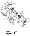
- Figur 5
- eine Expolsionsdarstellung des Kraftwagentürscharnieres nach Figur 1 bis 4.
Die beiden jeweils einen Scharnierstiftstummel sind in der gezeigten Ausführungsform als Kopfbolzen ausgebildet und liegen mit ihrem Kopf 13 wechselweise an der Außenfläche und der Innenfläche der beiden Profilschenkel 8 und 14 an. In den Scharnieraugen 5 und 6 der der übergriffenen Scharnierhälfte 2 sind die Lagerzapfen bildenden Längenabschnitte der Scharnierstiftstummel 11, 12 unter Zwischenschaltung von Lagerbuchsen aus einem wartungsfreien Lagermaterial aufgenommen
Die Profilschenkel 8 und 14 der übergreifenden Scharnierhälfte 1 weisen im Bereich der Scharnierachse 7 eine die Scharnieraugen 3 bis 6 überragende Höhe auf und sind über die übrige Länge der übergreifenden Scharnierhälfte 1 hin auf die Höhe einer Randabwinkelung 15 deren Profilgrundes 18 beschränkt. Im Profilgrund 19 der übergriffenen Scharnierhälfte 2 ist eine parallel zu deren dem eingreifenden Profilschenkel 8 der übergreifenden Scharnierhälfte 1 zugeordneten Profilschenkel 9 ausgerichtete und an diesen angrenzende Schlitzausnehmung 16 ausgeschnitten. In Scharnierquerrichtung ist an die Schlitzausnehmung 16 angrenzend eine sich über einen der axialen Länge des das Scharnierauge 3 der übergreifenden Scharnierhälfte 2 überragenden Teiles des Scharnierstiftstummels 11 entsprechende Breite erstreckende Erweiterung 17 der Schlitzausnehmung 16 angeordnet. Die Länge der Schlitzausnehmung 16 ist dabei so bemessen, daß der Profilschenkel 8 der übergreifenden Scharnierhälfte 1 wenigstens bei in einer der Schließlage der Fahrzeugtüre entsprechenden Lage befindlicher Scharnierhälfte 1 im Eingriff steht. Das Ein-oder Aushängen des Scharnieres ist somit lediglich in einer einer Teilöffnungslage der Türe entsprechenden Verschwenkstellung der beiden Scharnierhälften 1 und 2 möglich.
Zur Ausbildung eines Öffnungsendanschlages bzw. einer Schwenkwinkelbegrenzung ist an einem 10 der beiden Porfilschenkel der übergriffenen Scharnierhälfte 2 ein radial zur Scharnierachse 7 gerichteter Vorsprung 20 freigeschnitten, welcher mit einer nach innen gerichteten Randabstellung 21 des Profilgrundes der übergreifenden Scharnierhälfte 1 zusammenwirkt.
Die in deren wenigstens einer verrasteten Schwenkstellung mit dem scharnieraugenseitigen Strinende der übergreifenden Scharnierhälfte zusammenwirkende Haltenase 27 ist an eine die Stirnseite des Profilschenkels 9 der übergriffenen Scharnierhälfte 2 umgreifende Abwinkelung 30 des anderen Armes 24 der Rastfeder 22 anschließend ausgebildet und im wesentlichen parallel zur Ebene des Profilschenkels 9 der übergriffenen Scharnierhälfte 2 ausgerichtet. Die Rastvorsprünge 25,26 am innenliegenden Arm 23 der Rastfeder 22 sind so angeordnet, daß die an deren anderen Arm 24 ausgebildete Haltenase 27 die Schwenkbeweglichkeit der übergreifenden Scharnierhälfte 1 aufhebt und zwar bei in der Schließlage der Türe entsprechender Stellung der übergreifenden Scharnierhälfte 1.
Profilgrund 19 und Profilschenkel 9,10 der übergriffenen Scharnierhälfte 2 sind an ihrem den Scharnieraugen 5,6 abgewandten Enden jeweils rechtwinkelig zu ihrer Längserstreckung abgestellt und im Bereich ihrer Abstellung 31,32 mit nach innen gerichteten, sickenartigen Versteifungen 33 bildenden Durchprägungen versehen.
Claims (17)
- Aushängbares Türscharnier für Kraftwagentüren, bestehend aus zwei jeweils an einem Türanordnungsteil, Tür oder Türsäule ,befestigbaren Scharnierhälften, deren jede zwei in einem Abstand voneinander angeordnete zueinander fluchtende Scharnieraugen aufweist, und zwei Scharnierstiftstummeln, deren jeder in einem der beiden Scharnieraugen der einen Scharnierhälfte festgelegt ist und bei eingehängtem Scharnier in das komplementäre Scharnierauge der anderen Scharnierhälfte eingreift, wobei an beiden Scharnierhälften wechselseitig Vorsprünge und Ausnehmungen vorgesehen sind, welche bei eingehängtem Scharnier wenigstens über dessen Betriebsschwenkwinkel hin ineinandergreifen und eine Sicherung gegen ein unbeabsichtigtes Aushängen des Scharnieres bilden,
dadurch gekennzeichnet, daß
die beiden Scharnierhälften jeweils durch einen gefalteten Blechmaterialzuschnitt gebildet sind und mindestens im Bereich der Scharnierachse eine U-förmige Profilquerschnittsform aufweisen und daß die Scharnieraugen in den Profilschenkeln der U-förmigen Profilquerschnittsform der beiden Scharnierhälften angeordnet sind und daß den beiden Scharnierhälften ferner eine Einrichtung zur gegenseitigen Arretierung der beiden Scharnierhälften sowohl in einer der geschlossenen als auch in einer weiteren der teilweise geöffneten Stellung der Türe entsprechenden Verschwenkstellung zugeordnet ist.. - Türscharnier nach Anspruch 1, dadurch gekennzeichnet, daß die beiden Scharnierhälften einander mit ihrem Profilgrund übergreifend und die Scharnierstiftstummel an in den Scharnieraugen der übergreifenden Scharnierhälfte angeordnet sind.
- Türscharnier nach Anspruch 1 und 2, dadurch gekennzeichnet, daß der eine Profilschenkel der übergreifenden Scharnierhälfte zwischen die beiden Profilschenkel der übergriffenen Scharnierhälfte eingreift.
- Türscharnier nach Anspruch 1 bis 3, dadurch gekennzeichnet, daß im Profilgrund der übergriffenen Scharnierhälfte eine parallel zu deren einem Profilschenkel ausgerichtete und an diesen angrenzende Schlitzausnehmung für den zugeordneten Profilschenkel der übergreifenden Scharnierhälfte ausgeschnitten ist.
- Türscharnier nach Anspruch 1 bis 4, dadurch gekennzeichnet, daß im Profilgrund der übergriffenen Scharnierhälfte an die Schlitzausnehmung angrenzend eine sich in Richtung der Scharnierachse über eine der axialen Länge des das Scharnierauge der übergreifenden Scharnierhälfte überragenden Teiles des Scharnierstiftstummels entsprechende Breite hin erstreckende Erweiterung der Schlitzausnehmung angeordnet ist.
- Türscharnier nach Anspruch 1 bis 5, dadurch gekennzeichnet, daß die die Scharnieraugen aufweisenden Profilschenkel der übergreifenden Scharnierhälfte lediglich im Bereich der Scharnierlagerung eine die Scharnieraugen überragende Höhe aufweisen.
- Türscharnier nach Anspruch 1 bis 6, dadurch gekennzeichnet, daß der Profilgrund der übergreifenden Scharnierhälfte an seinem den Scharnieraugen benachbarten Ende gegen die Scharnierachse hin nach innen abgewinkelt ist.
- Türscharnier nach Anspruch 1 bis 7, dadurch gekennzeichnet, daß an einem der beiden Profilschenkel der übergriffenen Scharnierhälfte eine Rastfeder angeordnet ist, weiche aus einem Federblechzuschnitt geformt und um eine zur Scharnierachse konzentrische Achse schwenkbar an der Außenseite des Profilschenkels gelagert sowie mit einander bezüglich der Scharnierachse gegenüberliegenden Armen ausgestattet ist, wobei deren einer Arm eine im wesentlichen trapezförmige Grundrißform aufweist, in derem Endbereich zwei zueinander beabstandete, entlang einer zur Achse des Scharnierauges konzentrischen Kreisbahn ausgebildete Rastenvorsprünge und wobei deren andererArm zu einer Haltenase ausgeformt ist.
- Türscharnier nach Anspruch 1 bis 8, dadurch gekennzeichnet, daß die Rastfeder schwenkbeweglich im Scharnierauge gelagert ist.
- Türscharnier nach Anspruch 1 bis 9, dadurch gekennzeichnet, daß den beiden zueinander beabstandeten Rastenvorsprüngen der Rastfeder eine Rastausnehmung in der Flankenfläche des die Rastfeder tragenden Profilschenkels der übergriffenen Scharnierhälfte zugeordnet ist.
- Türscharnier nach Anspruch 1 bis 10, dadurch gekennzeichnet, daß die Haltenase der Rastfeder an einer die Stirnfläche des die Rastfeder tragenden Profilschenkels der übergriffenen Scharnierhälfte umgreifenden Abwinkelung zweiten Armes der Rastfeder angeordnet ist und mindestens in einer Schwenkstellung der Rastfeder mit dem vorderen Ende des Profilgrundes der übergreifenden Scharnierhälfte zusammenwirkt.
- Türscharnier nach Anspruch 1 bis 11, dadurch gekennzeichnet, daß Profilgrund und Profilschenkel der übergriffenen Scharnierhälfte an ihrem den Scharnieraugen abgewandten Enden jeweils rechtwinkelig zu ihrer Längserstreckung abgestellt und im Bereich ihrer Abstellung mit nach innen gerichteten, Versteifungen bildenden Durchprägungen versehen sind.
- Türscharnier nach Anspruch 1 bis 12, dadurch gekennzeichnet, daß die beiden jeweils einen Scharnierstiftstummel bildenden Scharnierzapfen in den Scharnieraugen der übergreifenden Scharnierhälfte drehsicher und axial unverschieblich festgelegt sind.
- Türscharnier nach Anspruch 1 bis 13, dadurch gekennzeichnet, daß die beiden jeweils einen Scharnierstiftstummel bildenden Scharnierzapfen in den Scharnieraugen der übergriffenen Scharnierhälfte jeweils unter Zwischenschaltung von Lagerbuchsen aus einem wartungsfreien Lagermaterial aufgenommen sind.
- Türscharnier nach Anspruch 1 bis 14, dadurch gekennzeichnet, daß Profilgrund und Profilschenkel der übergriffenen Scharnierhälfte an ihrem den Scharnieraugen abgewandten Enden jeweils rechtwinkelig zu ihrer Längserstreckung abgestellte Befestigungsflansche aufweisen.
- Türscharnier nach Anspruch 1 bis 15, dadurch gekennzeichnet, daß der in Verlängerung des Profilgrundes ausgebildete Befestigungsflansch bezüglich der Profilquerschnittsform nach innen und die in Verlängerung der Profilschenkel bezüglich der Profilquerschnittsform nach außen abgestellt sind.
- Türscharnier nach Anspruch 1 bis 16, dadurch gekennzeichnet, daß im Bereich der Abstellung der abgestellten Befestigungsflansche an Profilgrund und Profilschenkel der übergriffenen Scharnierhälfte mit nach innen gerichteten, sickenartigen Versteifungen bildenden Durchprägungen versehen sind.
Applications Claiming Priority (4)
| Application Number | Priority Date | Filing Date | Title |
|---|---|---|---|
| DE29620782U | 1996-11-30 | ||
| DE29620782 | 1996-11-30 | ||
| DE19652625A DE19652625A1 (de) | 1996-11-30 | 1996-12-18 | Aushängbares Türscharnier für Kraftwagentüren |
| DE19652625 | 1996-12-18 |
Publications (3)
| Publication Number | Publication Date |
|---|---|
| EP0845568A2 true EP0845568A2 (de) | 1998-06-03 |
| EP0845568A3 EP0845568A3 (de) | 2000-01-19 |
| EP0845568B1 EP0845568B1 (de) | 2001-03-28 |
Family
ID=26032371
Family Applications (1)
| Application Number | Title | Priority Date | Filing Date |
|---|---|---|---|
| EP97119297A Expired - Lifetime EP0845568B1 (de) | 1996-11-30 | 1997-11-05 | Aushängbares Türscharnier für Kraftwagentüren |
Country Status (3)
| Country | Link |
|---|---|
| US (1) | US6070296A (de) |
| EP (1) | EP0845568B1 (de) |
| ES (1) | ES2156624T3 (de) |
Cited By (1)
| Publication number | Priority date | Publication date | Assignee | Title |
|---|---|---|---|---|
| DE10356461B3 (de) * | 2003-12-03 | 2004-11-18 | Opel Eisenach Gmbh | Aushängbares Türscharnier für Kraftfahrzeuge |
Families Citing this family (9)
| Publication number | Priority date | Publication date | Assignee | Title |
|---|---|---|---|---|
| DE10118301B4 (de) * | 2001-04-12 | 2011-01-20 | Brückner, Lothar, Dr. | Kraftwagentürscharnier |
| US6357081B1 (en) * | 1999-09-22 | 2002-03-19 | Daimlerchrysler Corporation | Take apart door hinge with lock-on cam |
| US20060241496A1 (en) * | 2002-01-15 | 2006-10-26 | Xillix Technologies Corp. | Filter for use with imaging endoscopes |
| US20060273621A1 (en) * | 2005-06-06 | 2006-12-07 | Ventra Group, Inc. | Lift-off door hinge |
| DE102007006835A1 (de) * | 2007-02-07 | 2008-08-14 | Johnson Controls Gmbh | Aktuierungsmittel für eine crash-aktive Kopfstütze |
| US9103146B2 (en) * | 2013-07-26 | 2015-08-11 | Mitsui Kinzoku Act Corporation | Vehicle door hinge |
| US10780766B2 (en) | 2017-11-27 | 2020-09-22 | Ford Global Technologies, Llc | Vehicle door assemblies |
| US12312847B2 (en) * | 2019-12-03 | 2025-05-27 | Steven Alonzi | Door hinge with integrated door check |
| EP4033059A1 (de) | 2021-01-26 | 2022-07-27 | Edscha Engineering GmbH | Temporäre haltevorrichtung und fahrzeugscharnier |
Family Cites Families (7)
| Publication number | Priority date | Publication date | Assignee | Title |
|---|---|---|---|---|
| US2922669A (en) * | 1957-02-27 | 1960-01-26 | Alfred A E Hansen | Indexable joint |
| DE3644576C2 (de) * | 1986-12-08 | 1996-06-13 | Scharwaechter Gmbh Co Kg | Aushängbares Türschanier für Kraftwagentüren |
| US4766643A (en) * | 1986-12-29 | 1988-08-30 | Ford Motor Company | Vehicle door hinge having vertically separable pivotal connections |
| US4881298A (en) * | 1988-07-21 | 1989-11-21 | General Motors Corporation | Separable door hinge for vehicle body |
| FR2657112B3 (fr) * | 1990-01-16 | 1992-01-03 | Memo Spa | Charniere pour l'articulation d'une portiere sur la caisse d'un vehicule. |
| ES2130368T3 (es) * | 1993-11-13 | 1999-07-01 | Upf Group Plc | Bisagra. |
| US5570498A (en) * | 1995-05-02 | 1996-11-05 | General Motors Corporation | Lift-off door hinge |
-
1997
- 1997-11-05 ES ES97119297T patent/ES2156624T3/es not_active Expired - Lifetime
- 1997-11-05 EP EP97119297A patent/EP0845568B1/de not_active Expired - Lifetime
- 1997-12-01 US US08/982,060 patent/US6070296A/en not_active Expired - Fee Related
Cited By (1)
| Publication number | Priority date | Publication date | Assignee | Title |
|---|---|---|---|---|
| DE10356461B3 (de) * | 2003-12-03 | 2004-11-18 | Opel Eisenach Gmbh | Aushängbares Türscharnier für Kraftfahrzeuge |
Also Published As
| Publication number | Publication date |
|---|---|
| EP0845568A3 (de) | 2000-01-19 |
| US6070296A (en) | 2000-06-06 |
| EP0845568B1 (de) | 2001-03-28 |
| ES2156624T3 (es) | 2001-07-01 |
Similar Documents
| Publication | Publication Date | Title |
|---|---|---|
| EP0791715B1 (de) | Scharnier-und Feststellereinheit für aushängbare Kraftwagentüren | |
| DE2443472A1 (de) | Schiebetuer fuer fahrzeuge, insbesondere kraftfahrzeuge | |
| DE10013726C2 (de) | Klappenscharnier | |
| EP1930533A1 (de) | Kraftfahrzeugtürscharnier | |
| EP0678636B1 (de) | Verbindungsvorrichtung für den Einbau des Flügels eines Wohndachfensters in den Futterkasten | |
| DE69014873T2 (de) | Autoscharnier. | |
| EP0845568B1 (de) | Aushängbares Türscharnier für Kraftwagentüren | |
| EP3472904A1 (de) | Scharnieranordnung für einen schaltschrank | |
| EP2331367B1 (de) | Spiegelhalterung zum befestigen eines spiegels an einem fahrzeug und spiegel mit einer solchen spiegelhalterung | |
| EP0301131B1 (de) | Wischarm, insbesondere für Kraftfahrzeug-Scheibenwischeranlagen | |
| DE4209333C2 (de) | Mehrgelenkbeschlag für Fahrzeugtüren oder -klappen | |
| DE19652625A1 (de) | Aushängbares Türscharnier für Kraftwagentüren | |
| EP0226046B1 (de) | Scharnier | |
| DE3423416A1 (de) | Scheibenwischeranordnung, insbesondere fuer kraftfahrzeuge | |
| DE3137112C2 (de) | ||
| EP1561890B1 (de) | Türfeststelleinrichtung | |
| EP1129878B1 (de) | Türe oder sonstiges Karossererieteil eines Kraftfahrzeuges | |
| EP0785330B1 (de) | Heckklappenanlenkung für Kraftfahrzeuge | |
| DE19946666C2 (de) | Scharnieranordnung für eine Tür eines Kraftfahrzeugs | |
| DE3341855A1 (de) | Scharnier fuer tueren von kraftfahrzeug-kofferaufbauten, containern oder dergleichen | |
| DE4226718A1 (de) | Scharnier vom abhebbaren typ | |
| DE19509104C2 (de) | Trennbares Scharnier für Kraftwagen | |
| EP0769601B1 (de) | Türanlenksystem für Kraftwagentüren | |
| EP0523401B1 (de) | Türsicherung für ein mit einem Türfeststeller baulich vereinigtes Türscharnier | |
| EP2374973B1 (de) | Band für Türen, Fenster oder dergleichen |
Legal Events
| Date | Code | Title | Description |
|---|---|---|---|
| PUAI | Public reference made under article 153(3) epc to a published international application that has entered the european phase |
Free format text: ORIGINAL CODE: 0009012 |
|
| 17P | Request for examination filed |
Effective date: 19971105 |
|
| AK | Designated contracting states |
Kind code of ref document: A2 Designated state(s): DE ES FR GB IT |
|
| AX | Request for extension of the european patent |
Free format text: AL;LT;LV;MK;RO;SI |
|
| PUAL | Search report despatched |
Free format text: ORIGINAL CODE: 0009013 |
|
| AK | Designated contracting states |
Kind code of ref document: A3 Designated state(s): AT BE CH DE DK ES FI FR GB GR IE IT LI LU MC NL PT SE |
|
| AX | Request for extension of the european patent |
Free format text: AL;LT;LV;MK;RO;SI |
|
| GRAG | Despatch of communication of intention to grant |
Free format text: ORIGINAL CODE: EPIDOS AGRA |
|
| GRAG | Despatch of communication of intention to grant |
Free format text: ORIGINAL CODE: EPIDOS AGRA |
|
| GRAH | Despatch of communication of intention to grant a patent |
Free format text: ORIGINAL CODE: EPIDOS IGRA |
|
| 17Q | First examination report despatched |
Effective date: 20000803 |
|
| AKX | Designation fees paid |
Free format text: DE ES FR GB IT |
|
| GRAH | Despatch of communication of intention to grant a patent |
Free format text: ORIGINAL CODE: EPIDOS IGRA |
|
| GRAA | (expected) grant |
Free format text: ORIGINAL CODE: 0009210 |
|
| AK | Designated contracting states |
Kind code of ref document: B1 Designated state(s): DE ES FR GB IT |
|
| GBT | Gb: translation of ep patent filed (gb section 77(6)(a)/1977) |
Effective date: 20010328 |
|
| REF | Corresponds to: |
Ref document number: 59703228 Country of ref document: DE Date of ref document: 20010503 |
|
| ITF | It: translation for a ep patent filed | ||
| REG | Reference to a national code |
Ref country code: ES Ref legal event code: FG2A Ref document number: 2156624 Country of ref document: ES Kind code of ref document: T3 |
|
| ET | Fr: translation filed | ||
| PGFP | Annual fee paid to national office [announced via postgrant information from national office to epo] |
Ref country code: GB Payment date: 20011012 Year of fee payment: 5 |
|
| PGFP | Annual fee paid to national office [announced via postgrant information from national office to epo] |
Ref country code: FR Payment date: 20011106 Year of fee payment: 5 |
|
| PGFP | Annual fee paid to national office [announced via postgrant information from national office to epo] |
Ref country code: ES Payment date: 20011119 Year of fee payment: 5 |
|
| REG | Reference to a national code |
Ref country code: GB Ref legal event code: IF02 |
|
| PLBE | No opposition filed within time limit |
Free format text: ORIGINAL CODE: 0009261 |
|
| STAA | Information on the status of an ep patent application or granted ep patent |
Free format text: STATUS: NO OPPOSITION FILED WITHIN TIME LIMIT |
|
| 26N | No opposition filed | ||
| PG25 | Lapsed in a contracting state [announced via postgrant information from national office to epo] |
Ref country code: GB Free format text: LAPSE BECAUSE OF NON-PAYMENT OF DUE FEES Effective date: 20021105 |
|
| PG25 | Lapsed in a contracting state [announced via postgrant information from national office to epo] |
Ref country code: ES Free format text: LAPSE BECAUSE OF NON-PAYMENT OF DUE FEES Effective date: 20021106 |
|
| GBPC | Gb: european patent ceased through non-payment of renewal fee | ||
| PG25 | Lapsed in a contracting state [announced via postgrant information from national office to epo] |
Ref country code: FR Free format text: LAPSE BECAUSE OF NON-PAYMENT OF DUE FEES Effective date: 20030731 |
|
| REG | Reference to a national code |
Ref country code: FR Ref legal event code: ST |
|
| REG | Reference to a national code |
Ref country code: ES Ref legal event code: FD2A Effective date: 20031213 |
|
| PG25 | Lapsed in a contracting state [announced via postgrant information from national office to epo] |
Ref country code: IT Free format text: LAPSE BECAUSE OF NON-PAYMENT OF DUE FEES Effective date: 20051105 |
|
| REG | Reference to a national code |
Ref country code: DE Ref legal event code: R082 Ref document number: 59703228 Country of ref document: DE Representative=s name: BONNEKAMP & SPARING, DE Effective date: 20110812 Ref country code: DE Ref legal event code: R081 Ref document number: 59703228 Country of ref document: DE Owner name: EDSCHA ENGINEERING GMBH, DE Free format text: FORMER OWNER: ED. SCHARWAECHTER GMBH, 42855 REMSCHEID, DE Effective date: 20110812 |
|
| PGFP | Annual fee paid to national office [announced via postgrant information from national office to epo] |
Ref country code: DE Payment date: 20161121 Year of fee payment: 20 |
|
| REG | Reference to a national code |
Ref country code: DE Ref legal event code: R071 Ref document number: 59703228 Country of ref document: DE |