EP0845570A2 - Einklemmschutzsystem - Google Patents
Einklemmschutzsystem Download PDFInfo
- Publication number
- EP0845570A2 EP0845570A2 EP97309629A EP97309629A EP0845570A2 EP 0845570 A2 EP0845570 A2 EP 0845570A2 EP 97309629 A EP97309629 A EP 97309629A EP 97309629 A EP97309629 A EP 97309629A EP 0845570 A2 EP0845570 A2 EP 0845570A2
- Authority
- EP
- European Patent Office
- Prior art keywords
- sealing member
- base member
- web
- peripheral
- sensing resistor
- Prior art date
- Legal status (The legal status is an assumption and is not a legal conclusion. Google has not performed a legal analysis and makes no representation as to the accuracy of the status listed.)
- Withdrawn
Links
- 238000007789 sealing Methods 0.000 claims abstract description 52
- 230000002093 peripheral effect Effects 0.000 claims abstract description 26
- 239000011435 rock Substances 0.000 claims abstract description 13
- 230000003213 activating effect Effects 0.000 claims abstract description 4
- 230000001939 inductive effect Effects 0.000 claims description 2
- 230000000694 effects Effects 0.000 description 6
- 230000003993 interaction Effects 0.000 description 3
- 229920002943 EPDM rubber Polymers 0.000 description 2
- 206010064031 Limb crushing injury Diseases 0.000 description 1
- 230000004913 activation Effects 0.000 description 1
- 238000001514 detection method Methods 0.000 description 1
- 239000011521 glass Substances 0.000 description 1
- 238000010348 incorporation Methods 0.000 description 1
- 238000002955 isolation Methods 0.000 description 1
- 230000002028 premature Effects 0.000 description 1
Images

Classifications
-
- G—PHYSICS
- G01—MEASURING; TESTING
- G01L—MEASURING FORCE, STRESS, TORQUE, WORK, MECHANICAL POWER, MECHANICAL EFFICIENCY, OR FLUID PRESSURE
- G01L1/00—Measuring force or stress, in general
- G01L1/20—Measuring force or stress, in general by measuring variations in ohmic resistance of solid materials or of electrically-conductive fluids; by making use of electrokinetic cells, i.e. liquid-containing cells wherein an electrical potential is produced or varied upon the application of stress
-
- B—PERFORMING OPERATIONS; TRANSPORTING
- B60—VEHICLES IN GENERAL
- B60J—WINDOWS, WINDSCREENS, NON-FIXED ROOFS, DOORS, OR SIMILAR DEVICES FOR VEHICLES; REMOVABLE EXTERNAL PROTECTIVE COVERINGS SPECIALLY ADAPTED FOR VEHICLES
- B60J10/00—Sealing arrangements
-
- B—PERFORMING OPERATIONS; TRANSPORTING
- B60—VEHICLES IN GENERAL
- B60J—WINDOWS, WINDSCREENS, NON-FIXED ROOFS, DOORS, OR SIMILAR DEVICES FOR VEHICLES; REMOVABLE EXTERNAL PROTECTIVE COVERINGS SPECIALLY ADAPTED FOR VEHICLES
- B60J10/00—Sealing arrangements
- B60J10/70—Sealing arrangements specially adapted for windows or windscreens
- B60J10/74—Sealing arrangements specially adapted for windows or windscreens for sliding window panes, e.g. sash guides
-
- E—FIXED CONSTRUCTIONS
- E05—LOCKS; KEYS; WINDOW OR DOOR FITTINGS; SAFES
- E05F—DEVICES FOR MOVING WINGS INTO OPEN OR CLOSED POSITION; CHECKS FOR WINGS; WING FITTINGS NOT OTHERWISE PROVIDED FOR, CONCERNED WITH THE FUNCTIONING OF THE WING
- E05F15/00—Power-operated mechanisms for wings
- E05F15/40—Safety devices, e.g. detection of obstructions or end positions
- E05F15/42—Detection using safety edges
- E05F15/44—Detection using safety edges responsive to changes in electrical conductivity
- E05F15/443—Detection using safety edges responsive to changes in electrical conductivity specially adapted for vehicle windows or roofs
-
- E—FIXED CONSTRUCTIONS
- E05—LOCKS; KEYS; WINDOW OR DOOR FITTINGS; SAFES
- E05Y—INDEXING SCHEME ASSOCIATED WITH SUBCLASSES E05D AND E05F, RELATING TO CONSTRUCTION ELEMENTS, ELECTRIC CONTROL, POWER SUPPLY, POWER SIGNAL OR TRANSMISSION, USER INTERFACES, MOUNTING OR COUPLING, DETAILS, ACCESSORIES, AUXILIARY OPERATIONS NOT OTHERWISE PROVIDED FOR, APPLICATION THEREOF
- E05Y2900/00—Application of doors, windows, wings or fittings thereof
- E05Y2900/50—Application of doors, windows, wings or fittings thereof for vehicles
- E05Y2900/53—Type of wing
- E05Y2900/55—Windows
Definitions
- This invention relates to an anti-trap system and is particularly, but not exclusively, concerned with an arrangement to prevent fingers being trapped by a closing window pane in a motor vehicle. It is to be appreciated, however, that the system of the present invention can be employed in any other arrangement where it is desired to prevent an item (which may be animate or inanimate) from becoming painfully trapped by a closing closure member.
- the sensing means of interest in relation to the present invention is a so-called force sensing resistor (F.S.R.). Details of such a resistor are contained in Luxembourg Patent Specification No. 87942 in the name of Interlink Electronics Europe S.a.r.l.. That specification not only describes a force sensing resistor but also discloses its incorporation into a closing system, such as a sliding door.
- F.S.R. force sensing resistor
- an anti-trap system comprising:
- the anti-trap system of the present invention includes first retaining means intended to prevent the escape of the sealing member from the peripheral member, whilst allowing some relative movement between the sealing member and the peripheral member.
- the anti-trap system of the present invention also includes second retaining means intended to prevent escape of the sealing member from the base member, whilst allowing some relative movement between the base member and the sealing member.
- the base member has provision to allow one longitudinally extending region of the base member to rock without inducing too great a tendency to rock in adjacent longitudinal regions of the base member.
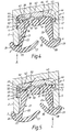
- FIG. 1 there is shown a peripheral member generally indicated by the reference numeral 1 which has a first side element in the form of a first side wall 2 having its own free end 3 and with, at an intermediate region along its length, a step (detent) 4 formed such that the free end region has a thickness greater than the remainder of the first side wall 2.
- the peripheral member 1 also has a second side element in the form of a second side wall 5 which has its own free end 6 and also has at an intermediate position along its length a step (detent) 7 which is a mirror image of the step 4.
- the peripheral member 1 also has, extending between the first and second side walls 2 and 5, a bridging element in the form of a bridge 8. Defined by the first side wall 2, the bridge 8 and the second side wall 5 is a recess 9.
- a reversibly movable closure member in the form of a window pane 11 having a leading edge 12 intended, during the closing mode, to move towards the anti-trap system so as to effect a seal.
- a channel-shaped sealing member 21 which has a first side wall 22, an opposing side wall 23 and, extending between the foot of the two side walls 22 and 23, a web 24.
- the first side wall 22 has a free end 25 extending outwardly from which is an outward lip 26 and extending inwardly is an inward lip 27.
- the second side wall 23 has a free end 28 from which outwardly projects an outer lip 29 and inwardly projects an inward lip 30.
- a limb 32 projecting towards the bridge 8 of the peripheral member 1 and from the free end region of which extends in an outwardly direction a projection 33 intended to abut the base member in a manner to be described hereinbelow.
- an outward projection 34 also, like the projection 33, intended to abut the base member in a manner to be described below.
- first side wall 22 Defined by the first side wall 22, the web 24 and the second side wall 23 is a channel 35 for receiving the leading edge 12 of the window pane 11.
- first recess 36 Adjacent to the foot of the limb 32, but on the opposite side to the projection 33, is a first recess 36 provided in the web 24 and/or the foot of the first side wall 22, and there is a second recess 37 spaced slightly from the first recess 36 and provided in the web 24 on that side thereof remote from the channel 35. Projecting between the first and second recesses 36 and 37 is an abutment region in the form of a nose 38.
- Another region of the web 24 on that side remote from the channel 35 has a rectilinear surface region 39.
- a base member 41 which is preferably more rigid than the sealing member 21.
- the base member 41 has a rectilinear upper surface 42 which smoothly abuts the bridge 8 of the peripheral member 1.
- the rectilinear surface 42 extends only over part of the upper surface of the base member 41, the right hand end region being a curved surface 43 leading on from the rectilinear surface 42.
- Curving round from the left hand end region of the rectilinear surface 42 of the base member 41 is an arm 44 which terminates in an inwardly directed hook capable of engaging with the projection 33 of the sealing member 21.
- the curved surface 43 of the base member 41 leads into a right hand arm 46 which terminates in an inwardly directed hook 47 which is capable of engaging with the projection 34 of the sealing member 21.
- the underside of the base member 41 is provided with two spaced-apart recesses, namely a first recess 48 and a second recess 49, and is also provided between those two recesses, with an abutment member in the form of a nose 50.
- To the right (in Figure 1) of the second recess 49 is a rectilinear surface 51 terminating in a step 52 which then leads into the right hand arm 46.
- the upper surface region of the base member 41 is provided with a series of spaced cuts 53, the purpose of which will be described in more detail hereinbelow.
- a force-sensing resistor generally indicated by the reference numeral 61.
- the resistor has, in going from its left hand end to its right hand end, a "dead” zone 62, an active zone 63 and another "dead” zone 64.
- the upper side of the dead zone 64 of the resistor 61 abuts the rectilinear surface 51 of the base member 41 and the lower side of the dead zone 64 of the resistor 61 abuts the rectilinear surface 39 of the sealing member 21.
- the majority of the active zone 63 of the resistor 61 is clear of abutting components.
- the nose 50 of the base member 41 just touches an upper central region of the active zone 63
- the nose 38 of the sealing member 21 just contacts a left hand end region of the active zone 63 of the resistor 61.
- the free end of the nose 50 lies in the same general plane as the rectilinear surface 51; and that the free end of the nose 38 lies in the same general plane as the rectilinear surface 39.
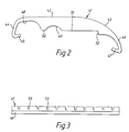
- Figure 2 merely shows the base member 41 in more detail, in isolation.
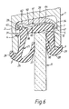
- Figure 3 is, as indicated above, a side view of the base member 41 showing, over the upper region of much of the base member 41 a series of cuts 53 provided at intervals. The purpose of these cuts is to allow one longitudinal portion of the base member 41 to rock, during the rocking mode described in more detail below, even when adjacent longitudinal portions of the base member 41 are not subjected to forces tending to cause them to rock. This is important because, in practice, a finger or other item which could be trapped is likely to extend over only a small portion of the total length of the anti-trap system.
- the upward movement of the first side wall 22 causes the nose 38 to act forcibly on the underside of the active zone 63 of the force sensitive resistor 61, thereby activating the resistor which, in turn, can through circuitry not shown cause a motor driving the window 11 in an upwardly direction firstly to stop and secondly to reverse to free the trapped item.
- the first side wall 22 remains in its starting position, being restrained from any tendency to move downwards by the interaction of the projection 31 on the step 4.
- the rocking action of the base member 41 causes the nose 50 of the base member 41 to act downwardly on the upper surface of the active zone 63 of the force sensitive resistor 61, causing the resistor to be urged downwardly onto the nose 38 of the sealing member 21, which nose 38 deforms and hence activates the active zone 63 of the sensor 61, thereby sending the appropriate signal to the motor.
- the left hand region of that base member moves downwardly, with the hook 45 of the base member 41 moving downwards and clear of the projection 33 of the sealing member 21.
- the moving edge 12 of the window pane 11 moves upwardly, causing upward deflection of the lips 27 and 30 but having no other significant effect upon the anti-trap system. Even if there is a tendency for slight overrun of the window 11, it merely abuts the web 24 of the sealing member 21 which causes force to be applied to the sensor 61 but only in the dead zone 64 thereof, so that the window can shut firmly without any inappropriate activation of the sensor 61 which might otherwise cause premature stopping of the window and even its reversal.
- the base member 41 can take the form of some appropriate extrudate or might be part of the window frame itself, being the upper part of the "door" of a motor vehicle.
- the sealing member 21 is typically an elastomeric glass run profile, and the base member 41 can be semi-rigid; in fact, it can have a Shore "A" hardness of 90 and the cuts 53 in the upper surface can, for instance, have a width of about 1.0mm ⁇ 0.5mm with the interval between the centre of one cut and the centre of the adjacent cut being, for instance, 14mm ⁇ 1mm.
- the sealing member 21 can be formed of ethylene propylene diene monomer (EPDM) with a Shore hardness of approximately 70.
- EPDM ethylene propylene diene monomer
Landscapes
- Engineering & Computer Science (AREA)
- Mechanical Engineering (AREA)
- Physics & Mathematics (AREA)
- General Physics & Mathematics (AREA)
- Window Of Vehicle (AREA)
- Air-Flow Control Members (AREA)
Applications Claiming Priority (2)
| Application Number | Priority Date | Filing Date | Title |
|---|---|---|---|
| GB9624744 | 1996-11-28 | ||
| GB9624744A GB2319804B (en) | 1996-11-28 | 1996-11-28 | Anti-trap system |
Publications (2)
| Publication Number | Publication Date |
|---|---|
| EP0845570A2 true EP0845570A2 (de) | 1998-06-03 |
| EP0845570A3 EP0845570A3 (de) | 1999-04-14 |
Family
ID=10803618
Family Applications (1)
| Application Number | Title | Priority Date | Filing Date |
|---|---|---|---|
| EP97309629A Withdrawn EP0845570A3 (de) | 1996-11-28 | 1997-11-28 | Einklemmschutzsystem |
Country Status (2)
| Country | Link |
|---|---|
| EP (1) | EP0845570A3 (de) |
| GB (1) | GB2319804B (de) |
Cited By (1)
| Publication number | Priority date | Publication date | Assignee | Title |
|---|---|---|---|---|
| US6337549B1 (en) | 2000-05-12 | 2002-01-08 | Anthony Gerald Bledin | Capacitive anti finger trap proximity sensor |
Family Cites Families (3)
| Publication number | Priority date | Publication date | Assignee | Title |
|---|---|---|---|---|
| DE19502033C1 (de) * | 1995-01-25 | 1996-06-13 | Daimler Benz Ag | Schutzeinrichtung für ein mittels eines Antriebs betätigbares Schließteil eines Kraftfahrzeugs |
| GB9509184D0 (en) * | 1995-05-05 | 1995-06-28 | Draftex Ind Ltd | Movable window safety device |
| GB9612679D0 (en) * | 1996-06-18 | 1996-08-21 | Draftex Ind Ltd | Movable-window safety device |
-
1996
- 1996-11-28 GB GB9624744A patent/GB2319804B/en not_active Expired - Fee Related
-
1997
- 1997-11-28 EP EP97309629A patent/EP0845570A3/de not_active Withdrawn
Cited By (1)
| Publication number | Priority date | Publication date | Assignee | Title |
|---|---|---|---|---|
| US6337549B1 (en) | 2000-05-12 | 2002-01-08 | Anthony Gerald Bledin | Capacitive anti finger trap proximity sensor |
Also Published As
| Publication number | Publication date |
|---|---|
| GB2319804A (en) | 1998-06-03 |
| EP0845570A3 (de) | 1999-04-14 |
| GB9624744D0 (en) | 1997-01-15 |
| GB2319804B (en) | 2001-03-14 |
Similar Documents
| Publication | Publication Date | Title |
|---|---|---|
| CN105620234B (zh) | 带有传感器的防护装置 | |
| US5463831A (en) | Weather strip for motor vehicle | |
| EP1697156B1 (de) | Dichtungs-, einfass oder zierleisten | |
| US6158170A (en) | Movable-window safety device | |
| US5847289A (en) | Profile for accommodating a sensor | |
| CN111196219B (zh) | 触控传感器的安装构造以及制造方法 | |
| KR100917942B1 (ko) | 창 | |
| US20100242373A1 (en) | Relief lip for flocked tape belt seal | |
| EP1036687A2 (de) | Dichtungsstreifen für Kraftfahrzeuge | |
| CA2050149A1 (en) | Glass run strip with chamfered edge transition | |
| EP0845570A2 (de) | Einklemmschutzsystem | |
| GB2340661A (en) | Force responsive sensor for automobiles | |
| US6223467B1 (en) | Motor vehicle sensor arrangement for detecting jamming | |
| US20050155293A1 (en) | Seals comprising at least one flexible lip designed to be in contact with a sliding window of an automobile | |
| US6779303B2 (en) | Vehicular power window safety device | |
| EP0619199B1 (de) | Dichtungs- und Wischanordnung | |
| US20070257449A1 (en) | Sealing molding for a Motor Vehicle | |
| EP0768201A1 (de) | Integrierte Innendichtungsstruktur für die Türfenster von Kraftfahrzeugen | |
| EP0663982A1 (de) | Wetter- und zugluftdichte vorrichtungen | |
| JP3079792B2 (ja) | 車両用ベルトモール | |
| GB2314378A (en) | Vehicle:powered sliding window:detecting obstruction | |
| JPH07329574A (ja) | 自動車用サッシレスドアのシール構造 | |
| JP4453002B2 (ja) | 遮蔽装置 | |
| US20020088182A1 (en) | Weather strip for an opening with which a motor-driven closure element is associated | |
| US7300093B2 (en) | Motor vehicle equipped with a pressure-sensitive tape next to the edge of an opening |
Legal Events
| Date | Code | Title | Description |
|---|---|---|---|
| PUAI | Public reference made under article 153(3) epc to a published international application that has entered the european phase |
Free format text: ORIGINAL CODE: 0009012 |
|
| AK | Designated contracting states |
Kind code of ref document: A2 Designated state(s): AT BE CH DE DK ES FI FR GB GR IE IT LI LU MC NL PT SE |
|
| AX | Request for extension of the european patent |
Free format text: AL;LT;LV;MK;RO;SI |
|
| PUAL | Search report despatched |
Free format text: ORIGINAL CODE: 0009013 |
|
| AK | Designated contracting states |
Kind code of ref document: A3 Designated state(s): AT BE CH DE DK ES FI FR GB GR IE IT LI LU MC NL PT SE |
|
| AX | Request for extension of the european patent |
Free format text: AL;LT;LV;MK;RO;SI |
|
| AKX | Designation fees paid | ||
| STAA | Information on the status of an ep patent application or granted ep patent |
Free format text: STATUS: THE APPLICATION IS DEEMED TO BE WITHDRAWN |
|
| REG | Reference to a national code |
Ref country code: DE Ref legal event code: 8566 |
|
| 18D | Application deemed to be withdrawn |
Effective date: 19991015 |