EP0845590A2 - Brennstoffpumpenmodul für Brennstofftank eines Fahrzeugs - Google Patents
Brennstoffpumpenmodul für Brennstofftank eines Fahrzeugs Download PDFInfo
- Publication number
- EP0845590A2 EP0845590A2 EP19970120066 EP97120066A EP0845590A2 EP 0845590 A2 EP0845590 A2 EP 0845590A2 EP 19970120066 EP19970120066 EP 19970120066 EP 97120066 A EP97120066 A EP 97120066A EP 0845590 A2 EP0845590 A2 EP 0845590A2
- Authority
- EP
- European Patent Office
- Prior art keywords
- fuel
- housing
- pump
- reservoir
- fuel tank
- Prior art date
- Legal status (The legal status is an assumption and is not a legal conclusion. Google has not performed a legal analysis and makes no representation as to the accuracy of the status listed.)
- Granted
Links
Images


Classifications
-
- F—MECHANICAL ENGINEERING; LIGHTING; HEATING; WEAPONS; BLASTING
- F02—COMBUSTION ENGINES; HOT-GAS OR COMBUSTION-PRODUCT ENGINE PLANTS
- F02M—SUPPLYING COMBUSTION ENGINES IN GENERAL WITH COMBUSTIBLE MIXTURES OR CONSTITUENTS THEREOF
- F02M37/00—Apparatus or systems for feeding liquid fuel from storage containers to carburettors or fuel-injection apparatus; Arrangements for purifying liquid fuel specially adapted for, or arranged on, internal-combustion engines
- F02M37/04—Feeding by means of driven pumps
- F02M37/08—Feeding by means of driven pumps electrically driven
- F02M37/10—Feeding by means of driven pumps electrically driven submerged in fuel, e.g. in reservoir
-
- Y—GENERAL TAGGING OF NEW TECHNOLOGICAL DEVELOPMENTS; GENERAL TAGGING OF CROSS-SECTIONAL TECHNOLOGIES SPANNING OVER SEVERAL SECTIONS OF THE IPC; TECHNICAL SUBJECTS COVERED BY FORMER USPC CROSS-REFERENCE ART COLLECTIONS [XRACs] AND DIGESTS
- Y10—TECHNICAL SUBJECTS COVERED BY FORMER USPC
- Y10T—TECHNICAL SUBJECTS COVERED BY FORMER US CLASSIFICATION
- Y10T137/00—Fluid handling
- Y10T137/8593—Systems
- Y10T137/86348—Tank with internally extending flow guide, pipe or conduit
Definitions
- the present invention relates to a fuel pump module for disposition within the fuel tank of an automotive vehicle and particularly to a fuel pump module which has fewer parts count than known fuel pump modules and is therefore less costly to fabricate and assemble.
- a fuel pump In automotive vehicles, a fuel pump is typically disposed within the fuel tank.
- the fuel pump inlet is typically referenced to the bottom of the fuel tank in order to prevent interruption of fuel flow to the engine when the fuel in the fuel tank is low or nearly empty.
- the pumps are located within the tank in a straight-up position, with an inlet spring-biased toward the bottom of the tank and having an associated filter.
- the fuel tank inlet may comprise flexible lines which are clipped to the bottom of the fuel tank, the fuel pump being located outside of the fuel tank.
- a fuel pump module is disposed within a fuel tank and contains the fuel pump.
- the fuel pump module is pivotally connected to a flange secured to a wall of the fuel tank so that the pump is referenced to the bottom of the fuel tank.
- the fuel pump module requires two structural members external to the module, i.e., a pivot arm and a guide arm, which also serve as fuel supply and fuel return lines, respectively.
- a compression spring is used to load or bias the module to the fuel tank bottom.
- the fabrication and assembly of these structures are quite costly and the designs are not particularly robust, causing durability problems. Fuel contamination is also a problem because these designs have an opening permitting fuel to enter and leave the reservoir.
- a fuel pump module for an automotive vehicle which has reduced parts count, can be relatively easily manufactured and assembled, employs a torsion spring to reference the bottom of the fuel tank, includes a pressure regulator within the module and includes a regulator mount having vibration isolation and anti-rotation features.
- the fuel return line is internal to the module housing for returning fuel to either a fuel reservoir within the housing or externally of the module to the vehicle fuel tank.
- the module also has a single external structural arm which serves as a fuel supply line.
- a torsion spring is disposed between the arm and the housing to bias the housing to the bottom wall of the fuel tank, the arm being connected to a flange connected to a structural wall of the fuel tank.
- the present fuel pump module is less costly and easier to assemble than conventional pivot pump modules, has fewer parts, and enables the housing to be sealed from the fuel in the fuel tank with the exception of the fuel inlet to a reservoir within the module housing body, the module also housing the fuel pump. Sealing the reservoir to the outside world (the fuel tank) is desirable so that contaminants do not find their way to the fuel pump, causing damage. Where the fuel return to the reservoir within the module housing body exceeds the fuel supplied to the fuel rail and the reservoir becomes full, a check valve is added to the housing to allow excess fuel to flow into the fuel tank.
- the regulator mounted within the module housing has a regulator mounting cup which serves as part of a fuel pump vibration isolation system, as well as an anti-rotational prevention mechanism.
- the regulator mounting cup is carried by the fuel pump and disposed within the module housing.
- the mounting cup includes a pocket for receiving a grommet formed along the underside of a cover sealed to the module housing body.
- the grommet and pocket are vibrationally-isolated one from the other, for example, by resilient material disposed therebetween.
- the pocket and grommet are off the axis of the pump whereby the pocket and grommet combine to prevent rotation of the pump relative to the module housing. It will be appreciated that the opposite end of the fuel pump is likewise isolated vibrationally from the module housing body.
- a fuel pump module for disposition in the fuel tank of an automotive vehicle to supply fuel to the engine of the vehicle, comprising a housing for disposition within the fuel tank including a fuel reservoir, a fuel pump within the housing for pumping fuel from the reservoir and having a fuel outlet, a first arm carried by and disposed externally of the housing, the member having a passageway for receiving fuel from the fuel pump, a flange for securement to the fuel tank, a second arm carried by the flange and pivotally coupled to the member, the second arm having a passageway in communication with the passageway of the first arm for flowing fuel from the reservoir to the engine of the vehicle and a torsion spring coupled between the arms for biasing the housing for movement relative to the flange for reference to a bottom of the fuel tank.
- a fuel pump module for disposition in the fuel tank of an automotive vehicle to supply fuel to the engine of the vehicle, comprising a housing for disposition within the fuel tank and including a fuel reservoir, a fuel pump within the housing for pumping fuel from the reservoir and having a rotational axis and a fuel outlet, a fuel regulator within the housing in communication with the outlet of the pump and having a port for returning fuel to the reservoir or the fuel tank, the regulator including a mount therefor for supporting the regulator on the fuel pump, the mount having a connection with the housing offset from the axis of rotation of the fuel pump.
- a fuel tank 10 for an automotive vehicle for supplying fuel to a fuel rail which, in turn, supplies fuel to an engine through a plurality of fuel injectors.
- the fuel rail, injectors and engine are conventional in construction and are therefore not illustrated.
- the fuel system illustrated is a non-return system where there is a single fuel line 12 between the fuel pump module, generally indicated 20, within the fuel tank 10 and the fuel rail without the necessity of a return line from the fuel rail to the fuel pump module or fuel tank.
- a pressure regulator may be supplied in the fuel pump module as described below.
- the fuel pump module of the present invention may be provided in a fuel system having an integral returnless pressure regulator/filter at the inlet to the fuel rail, for example, as described and illustrated in U.S. Patent No. 5,413,077 of common assignee herewith.
- the pump module hereof comprises a housing 22, preferably of a generally cylindrical configuration but which may take other shapes as desired, having a cylindrical body 24 and a top or cover 26 and defining a fuel reservoir within body 24.
- Cover 26 is preferably suitably releasably sealed to body 24, e.g., by a snapfit and O-rings.
- the cover can be permanently attached to body 24, e.g., by welding of the plastic cover to the plastic body 24.
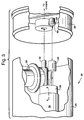
- Adjacent one end of the reservoir body 24 is a fuel inlet 28 ( Figure 1) having a fuel filter sock 31 whereby fuel from the fuel tank is admitted into the reservoir.
- fuel is aspirated from the fuel tank into the reservoir within body 24 by flow of a fuel return line through a venturi, not shown, internal of the fuel pump module.
- a fuel pump 30 within reservoir body 24 and which fuel pump may be of conventional construction.
- pump 30 may drive an impeller within a housing portion 33 about a rotational axis A - A generally parallel to the axis of cylindrical body 24 for pumping fuel to a fuel pump outlet 32.
- the fuel pump pumps fuel from the internal reservoir of the module to the fuel pump outlet 32 for supplying fuel externally of the fuel tank by structure and passageways, to be described, to the fuel rail, not shown.
- the fuel outlet 32 of the fuel pump 30 lies in communication with a fitting, i.e., generally pipe-shaped first arm 34, mounted on top of cover 26, the arm 34 being external to the body 22.
- the arm 34 has a right angle bend 35 and a passageway 37 in communication with the fuel pump outlet 32.
- a second arm 36 is pivotally mounted at one end within the bend 35 and is connected at its opposite end to a flange 40.
- the flange 40 is suitably secured to the wall of the fuel tank 10 and mounts the fuel pump module 20 within the fuel tank 10 as illustrated in Figure 1.
- Arm 38 also contains a fuel passageway 39 in communication with passageway 37.
- the fuel passageways 37 and 39 through the arms 34 and 38 terminate in a nipple 42 on the outer side of flange 40 and outside of the fuel tank for connection with a fuel supply line 12 for supplying fuel from the fuel pump module 20 to the fuel rail.
- the body 22 containing the fuel pump and reservoir is pivotally mounted to the arm 38 and structurally supported by the flange 40 so that the body 22 can always be referenced to the bottom of the fuel tank.
- a torsion spring 44 is coupled about the arm 34 and opposite ends of the torsion spring engage the member 38 and the cover 26, respectively.
- the torsion spring 44 is mounted such that a constant bias is provided between the fixed support structure provided by the flange 40 and arm 38 to the body 22 so that the body 22 is biased for reference to the bottom of the fuel tank.
- the sole structural support between flange 40 and the module housing body 22 is the member 34 and arm 38 pivotally coupled to one another and through which the fuel supply line passes.
- the flange 40 may have a fuel filter pocket 46 disposed along its underside for receiving a fuel filter, not shown.
- the fuel filter pocket may be located on the outside of the flange with a removable cover whereby access to the fuel filter can be provided from outside of the fuel tank.
- a pressure regulator 50 may be provided within the body 22, i.e., inside the fuel module.
- the necessary fuel return is provided through the pressure regulator for returning fuel to the reservoir.
- the fuel is pumped from the fuel pump to the fuel rail and the pressure regulator diverts excess fuel from the fuel supply line to the reservoir through an outlet of the pressure regulator.
- the regulator can be eliminated and replaced with a simple pressure relief valve, or if the system is deadheaded, then a fuel return is not necessary.
- the pressure regulator which per se may be a conventional integral regulator is mounted within a regulator mounting cup 52 secured to an outlet port of the pump 30.
- the mounting cup 52 includes a series of circular steps 54 which receive the regulator, the regulator 52 not being shown in Figures 5 and 6 but being illustrated in Figure 3.
- Fuel from the pump 30 passes through an inlet port 56 laterally outwardly through a port 58 into the regulator, with the fuel flowing from the regulator through the outlet port 58 in communication with the outlet 32.
- the return fuel from the regulator passes to the reservoir by way of an outlet port 60.
- a significant aspect of the present invention resides in the provision of a regulator pocket 62 formed along one side of the regulator mounting cup 52 and preferably formed integrally with cup 52.
- Pocket 62 comprises a generally cylindrical nipple open at one end for receiving a grommet or pin 64 projecting from the undersurface of the cover 26 of the body 22.
- the pin or interior portions of the pocket 62, or both, may be provided with vibration-isolation material, i.e., any known resilient material, for isolating the pump 30 from the body 22.
- vibration isolation material 63 may be disposed about pin 64.
- the opposite end of the pump 30 is likewise mounted in a resilient grommet, not shown, so that the pump is vibrationally isolated from the body 22.
- the pocket 62 and grommet 64 are off-axis relative to the cylindrical body 22 such that the pocket and pin serve to prevent rotation of the pump 30 relative to the housing 22.
- a further important aspect of the present invention is that the reservoir is sealed.
- the cover 26 may be sealed to the body 22 via a welding operation or an O-ring may be used in a snapfit. Alternatively, a simple pressfit may be utilized. Sealing the reservoir from the fuel tank is desirable so that contaminants do not find their way to the fuel pump, causing damage. Should the fuel return exceed the fuel supplied and the reservoir becomes full, a check valve 66 can be added to the body 22 to relieve excess pressure and return fuel to the fuel tank 10.
- the objectives of the present invention are fully accomplished in the foregoing described fuel pump, particularly in that the parts count for the fuel pump module is substantially reduced as compared with prior fuel pump modules.
- a single structural connection comprised of two arms pivotally coupled one to the other between the structural support, i.e., the flange, and the module housing is necessary.
- the design also enables the mounting of a pressure regulator within the body 22, as well as a filter, as necessary.
- the pocket and grommet arrangement of the regulator mounting cup 52 and cover 26 vibrationally isolate the fuel pump 30 from housing body 22 while simultaneously preventing rotation of the fuel pump 30 relative to the housing body 22.
- the torsion spring also allows the reservoir to be referenced at all times to the bottom of the fuel tank for low fuel derivability and without the necessity of further structural interconnections between the flange 40 and the body 22.
Landscapes
- Engineering & Computer Science (AREA)
- Chemical & Material Sciences (AREA)
- Combustion & Propulsion (AREA)
- Mechanical Engineering (AREA)
- General Engineering & Computer Science (AREA)
- Cooling, Air Intake And Gas Exhaust, And Fuel Tank Arrangements In Propulsion Units (AREA)
Applications Claiming Priority (2)
| Application Number | Priority Date | Filing Date | Title |
|---|---|---|---|
| US757868 | 1996-11-27 | ||
| US08/757,868 US6014957A (en) | 1996-11-27 | 1996-11-27 | Fuel pump module for the fuel tank of an automotive vehicle |
Publications (3)
| Publication Number | Publication Date |
|---|---|
| EP0845590A2 true EP0845590A2 (de) | 1998-06-03 |
| EP0845590A3 EP0845590A3 (de) | 1998-11-25 |
| EP0845590B1 EP0845590B1 (de) | 2002-05-08 |
Family
ID=25049554
Family Applications (1)
| Application Number | Title | Priority Date | Filing Date |
|---|---|---|---|
| EP19970120066 Expired - Lifetime EP0845590B1 (de) | 1996-11-27 | 1997-11-17 | Brennstoffpumpenmodul für Brennstofftank eines Fahrzeugs |
Country Status (3)
| Country | Link |
|---|---|
| US (1) | US6014957A (de) |
| EP (1) | EP0845590B1 (de) |
| DE (1) | DE69712444T2 (de) |
Cited By (2)
| Publication number | Priority date | Publication date | Assignee | Title |
|---|---|---|---|---|
| EP0941885A3 (de) * | 1998-03-12 | 2000-11-15 | Toyo Roki Seizo Kabushiki Kaisha | Kraftstoffzufuhreinrichtung |
| CN106574585A (zh) * | 2014-08-26 | 2017-04-19 | 爱三工业株式会社 | 燃料供给装置 |
Families Citing this family (16)
| Publication number | Priority date | Publication date | Assignee | Title |
|---|---|---|---|---|
| US6155238A (en) * | 1999-04-01 | 2000-12-05 | Walbro Corporation | Fuel pressure regulator and fuel filter module |
| US20060000454A1 (en) * | 2004-07-02 | 2006-01-05 | Visteon Global Technologies, Inc. | In-tank fuel supply unit having long life filter |
| FR2885179B1 (fr) * | 2005-04-27 | 2007-10-12 | Ti Fuel Systems Sas Soc Par Ac | Ensemble comprenant un module de puisage et filtre a charbon actif pour reserv0ir de carburant de vehicule automobile |
| US7237538B2 (en) * | 2005-09-09 | 2007-07-03 | Ti Automotive Fuel Systems Sas | Modular fuel delivery assembly |
| US20070107700A1 (en) * | 2005-10-05 | 2007-05-17 | Milton Jeffery J | Side mounted fuel pump module with bottom referencing filter |
| US7418950B2 (en) * | 2005-12-22 | 2008-09-02 | Chrysler Llc | Fuel pump and tank assembly for an automotive vehicle |
| EP2021615A1 (de) * | 2006-05-04 | 2009-02-11 | Continental Automotive Systems US, Inc. | Kraftstoffversorgungsmodul für anwendungen mit niedriger einbauhöhe |
| US8397698B2 (en) * | 2008-01-28 | 2013-03-19 | Chrysler Group Llc | Composite fuel pump cartridge and fuel tank assembly |
| US20120294732A1 (en) * | 2011-05-17 | 2012-11-22 | Holley Performance Products | Pump System and Method of Use |
| US9879662B2 (en) | 2011-05-17 | 2018-01-30 | Holley Performance Products, Inc. | Inline pump assembly and method |
| US8372278B1 (en) * | 2012-03-21 | 2013-02-12 | GM Global Technology Operations LLC | Liquid fuel strainer assembly |
| JP6258158B2 (ja) * | 2014-08-26 | 2018-01-10 | 愛三工業株式会社 | 燃料供給装置 |
| JP2017008761A (ja) * | 2015-06-18 | 2017-01-12 | 愛三工業株式会社 | 燃料タンク |
| JP6414113B2 (ja) * | 2016-03-24 | 2018-10-31 | 株式会社デンソー | 燃料供給装置 |
| KR20230028825A (ko) * | 2021-08-23 | 2023-03-03 | 현대자동차주식회사 | 차량용 연료펌프 모듈 |
| US12103379B2 (en) * | 2021-09-02 | 2024-10-01 | Richard Mellick Zock | Modified gas tank with built-in fuel pump with internal regulator adapted for utility, off-road, and all-terrain vehicles and a method of installing the same |
Citations (1)
| Publication number | Priority date | Publication date | Assignee | Title |
|---|---|---|---|---|
| US5413077A (en) | 1994-05-09 | 1995-05-09 | Siemens Automotive L.P. | Non-return fuel system with fuel pressure vacuum response |
Family Cites Families (15)
| Publication number | Priority date | Publication date | Assignee | Title |
|---|---|---|---|---|
| US3470907A (en) * | 1966-05-09 | 1969-10-07 | Kaiser Jeep Corp | One-piece plastic gas tank and fuel level sensing apparatus and method |
| US4569637A (en) * | 1984-02-22 | 1986-02-11 | Walbro Corporation | In-tank fuel pump assembly |
| US4694857A (en) * | 1986-03-31 | 1987-09-22 | Stant Inc. | Fuel sender unit |
| US4844704A (en) * | 1986-04-03 | 1989-07-04 | Honda Giken Kogyo Kabushiki Kaisha | Fuel pump assembly |
| US4869225A (en) * | 1987-10-26 | 1989-09-26 | Nippondenso Co., Ltd. | Fuel supply device for vehicles |
| US4750513A (en) * | 1987-11-19 | 1988-06-14 | Chrysler Motors Corporation | Pivotally mounted fuel collector |
| US5038741A (en) * | 1990-04-13 | 1991-08-13 | Walbro Corporation | In-tank fuel module |
| US5080077A (en) * | 1990-06-01 | 1992-01-14 | General Motors Corporation | Modular fuel delivery system |
| US5181839A (en) * | 1992-01-09 | 1993-01-26 | Walbro Corporation | Quick connect fuel pump assembly |
| US5195494A (en) * | 1992-02-27 | 1993-03-23 | Walbro Corporation | Fuel delivery system with outlet pressure regulation |
| JP3734281B2 (ja) * | 1993-09-10 | 2006-01-11 | 株式会社デンソー | インタンク式燃料ポンプ |
| DE4336858C1 (de) * | 1993-10-28 | 1995-01-05 | Bayerische Motoren Werke Ag | Fördereinheit mit einem Füllstandsgeber |
| FR2715973B1 (fr) * | 1994-02-08 | 1996-04-26 | Marwal Systems | Régulateur de pression interne à l'embase d'un ensemble de puisage. |
| DE4411566C2 (de) * | 1994-04-02 | 2000-08-31 | Mannesmann Vdo Ag | Kraftstofftank mit im Tankinneren angeordneter Pumpeneinheit |
| US5482444A (en) * | 1994-09-06 | 1996-01-09 | General Motors Corporation | Vibration isolating mounting for an electric fuel pump |
-
1996
- 1996-11-27 US US08/757,868 patent/US6014957A/en not_active Expired - Fee Related
-
1997
- 1997-11-17 EP EP19970120066 patent/EP0845590B1/de not_active Expired - Lifetime
- 1997-11-17 DE DE69712444T patent/DE69712444T2/de not_active Expired - Fee Related
Patent Citations (1)
| Publication number | Priority date | Publication date | Assignee | Title |
|---|---|---|---|---|
| US5413077A (en) | 1994-05-09 | 1995-05-09 | Siemens Automotive L.P. | Non-return fuel system with fuel pressure vacuum response |
Cited By (5)
| Publication number | Priority date | Publication date | Assignee | Title |
|---|---|---|---|---|
| EP0941885A3 (de) * | 1998-03-12 | 2000-11-15 | Toyo Roki Seizo Kabushiki Kaisha | Kraftstoffzufuhreinrichtung |
| US6206037B1 (en) | 1998-03-12 | 2001-03-27 | Toyo Roki Seizo Kabushiki Kaisha | Fuel supplying apparatus |
| US6308733B2 (en) | 1998-03-12 | 2001-10-30 | Toyo Roki Seizo Kabushiki Kaisha | Fuel supplying apparatus |
| US6401751B2 (en) | 1998-03-12 | 2002-06-11 | Toyo Roki Seizo Kabushiki Kaisha | Fuel supplying apparatus |
| CN106574585A (zh) * | 2014-08-26 | 2017-04-19 | 爱三工业株式会社 | 燃料供给装置 |
Also Published As
| Publication number | Publication date |
|---|---|
| DE69712444T2 (de) | 2002-11-07 |
| EP0845590B1 (de) | 2002-05-08 |
| EP0845590A3 (de) | 1998-11-25 |
| US6014957A (en) | 2000-01-18 |
| DE69712444D1 (de) | 2002-06-13 |
Similar Documents
| Publication | Publication Date | Title |
|---|---|---|
| EP0845590B1 (de) | Brennstoffpumpenmodul für Brennstofftank eines Fahrzeugs | |
| EP0959241B1 (de) | Brandstoffzufuhr für fahrzeuge | |
| US6260543B1 (en) | Fuel delivery module with integrated filter | |
| US6253790B1 (en) | Fuel tank for motorcycle | |
| EP0425105B1 (de) | Bausteinsystem für die Kraftstoffzufuhr | |
| US6029633A (en) | Passive fuel delivery module and suspension mechanism | |
| US5992394A (en) | Fuel supply device housing pump and filter in sub-tank | |
| US6719539B1 (en) | Fuel feeder | |
| US20090194074A1 (en) | Fuel Delivery System for Engine | |
| US5875816A (en) | Fuel feeding module with integrated fuel fine filter | |
| JP4248075B2 (ja) | 燃料供給装置 | |
| US7717466B2 (en) | Mounting structure for fuel pump of vehicle engine and vehicle installing the same | |
| US6679229B2 (en) | Fuel supply apparatus in outboard engine | |
| US6293258B1 (en) | Fuel supply module | |
| US6773241B2 (en) | Pump unit | |
| US7556024B2 (en) | Fuel supply module | |
| EP0881379A2 (de) | Brennstoffördersystem für eine Brennkraftmaschine | |
| US6325048B1 (en) | Integrated mounting of a pressure regulator in an automotive fuel system | |
| CN111936736B (zh) | 燃料供给装置 | |
| JP3908931B2 (ja) | 小型車両用燃料供給ユニット | |
| US6722346B2 (en) | Connection | |
| US11707979B2 (en) | Fuel pump module | |
| US20040173188A1 (en) | Device for supplying fuel from a tank to an internal combustion engine | |
| ES2239421T3 (es) | Estructura para el montaje de una bobma electrica en el deposito de combustible de un vehiculo a motor y un respectivo filtro de entrada. | |
| US20120251341A1 (en) | Fuel pump module including a horizontal sender gauge |
Legal Events
| Date | Code | Title | Description |
|---|---|---|---|
| PUAI | Public reference made under article 153(3) epc to a published international application that has entered the european phase |
Free format text: ORIGINAL CODE: 0009012 |
|
| AK | Designated contracting states |
Kind code of ref document: A2 Designated state(s): DE FR GB IT |
|
| AX | Request for extension of the european patent |
Free format text: AL;LT;LV;MK;RO;SI |
|
| PUAL | Search report despatched |
Free format text: ORIGINAL CODE: 0009013 |
|
| AK | Designated contracting states |
Kind code of ref document: A3 Designated state(s): AT BE CH DE DK ES FI FR GB GR IE IT LI LU MC NL PT SE |
|
| AX | Request for extension of the european patent |
Free format text: AL;LT;LV;MK;RO;SI |
|
| 17P | Request for examination filed |
Effective date: 19981110 |
|
| AKX | Designation fees paid |
Free format text: DE FR GB IT |
|
| 17Q | First examination report despatched |
Effective date: 20010301 |
|
| GRAG | Despatch of communication of intention to grant |
Free format text: ORIGINAL CODE: EPIDOS AGRA |
|
| GRAG | Despatch of communication of intention to grant |
Free format text: ORIGINAL CODE: EPIDOS AGRA |
|
| GRAH | Despatch of communication of intention to grant a patent |
Free format text: ORIGINAL CODE: EPIDOS IGRA |
|
| REG | Reference to a national code |
Ref country code: GB Ref legal event code: IF02 |
|
| GRAH | Despatch of communication of intention to grant a patent |
Free format text: ORIGINAL CODE: EPIDOS IGRA |
|
| GRAA | (expected) grant |
Free format text: ORIGINAL CODE: 0009210 |
|
| AK | Designated contracting states |
Kind code of ref document: B1 Designated state(s): DE FR GB IT |
|
| REF | Corresponds to: |
Ref document number: 69712444 Country of ref document: DE Date of ref document: 20020613 |
|
| RAP2 | Party data changed (patent owner data changed or rights of a patent transferred) |
Owner name: SIEMENS VDO AUTOMOTIVE CORPORATION |
|
| ET | Fr: translation filed | ||
| PGFP | Annual fee paid to national office [announced via postgrant information from national office to epo] |
Ref country code: GB Payment date: 20021107 Year of fee payment: 6 |
|
| PGFP | Annual fee paid to national office [announced via postgrant information from national office to epo] |
Ref country code: FR Payment date: 20021129 Year of fee payment: 6 |
|
| PGFP | Annual fee paid to national office [announced via postgrant information from national office to epo] |
Ref country code: DE Payment date: 20030120 Year of fee payment: 6 |
|
| PLBE | No opposition filed within time limit |
Free format text: ORIGINAL CODE: 0009261 |
|
| STAA | Information on the status of an ep patent application or granted ep patent |
Free format text: STATUS: NO OPPOSITION FILED WITHIN TIME LIMIT |
|
| 26N | No opposition filed |
Effective date: 20030211 |
|
| PG25 | Lapsed in a contracting state [announced via postgrant information from national office to epo] |
Ref country code: GB Free format text: LAPSE BECAUSE OF NON-PAYMENT OF DUE FEES Effective date: 20031117 |
|
| PG25 | Lapsed in a contracting state [announced via postgrant information from national office to epo] |
Ref country code: DE Free format text: LAPSE BECAUSE OF NON-PAYMENT OF DUE FEES Effective date: 20040602 |
|
| GBPC | Gb: european patent ceased through non-payment of renewal fee |
Effective date: 20031117 |
|
| PG25 | Lapsed in a contracting state [announced via postgrant information from national office to epo] |
Ref country code: FR Free format text: LAPSE BECAUSE OF NON-PAYMENT OF DUE FEES Effective date: 20040730 |
|
| REG | Reference to a national code |
Ref country code: FR Ref legal event code: ST |
|
| PG25 | Lapsed in a contracting state [announced via postgrant information from national office to epo] |
Ref country code: IT Free format text: LAPSE BECAUSE OF NON-PAYMENT OF DUE FEES;WARNING: LAPSES OF ITALIAN PATENTS WITH EFFECTIVE DATE BEFORE 2007 MAY HAVE OCCURRED AT ANY TIME BEFORE 2007. THE CORRECT EFFECTIVE DATE MAY BE DIFFERENT FROM THE ONE RECORDED. Effective date: 20051117 |