EP0845633A1 - Einbau- Beleuchtungseinrichtung - Google Patents
Einbau- Beleuchtungseinrichtung Download PDFInfo
- Publication number
- EP0845633A1 EP0845633A1 EP97402876A EP97402876A EP0845633A1 EP 0845633 A1 EP0845633 A1 EP 0845633A1 EP 97402876 A EP97402876 A EP 97402876A EP 97402876 A EP97402876 A EP 97402876A EP 0845633 A1 EP0845633 A1 EP 0845633A1
- Authority
- EP
- European Patent Office
- Prior art keywords
- support
- ring
- membrane
- intermediate piece
- reflector
- Prior art date
- Legal status (The legal status is an assumption and is not a legal conclusion. Google has not performed a legal analysis and makes no representation as to the accuracy of the status listed.)
- Withdrawn
Links
- 239000012528 membrane Substances 0.000 claims abstract description 30
- 230000000284 resting effect Effects 0.000 claims description 3
- 239000013536 elastomeric material Substances 0.000 claims description 2
- 229920001971 elastomer Polymers 0.000 abstract description 3
- 239000000806 elastomer Substances 0.000 abstract description 3
- 239000000463 material Substances 0.000 abstract description 3
- 238000005192 partition Methods 0.000 abstract 1
- 229940082150 encore Drugs 0.000 description 4
- 229910001234 light alloy Inorganic materials 0.000 description 3
- 239000002184 metal Substances 0.000 description 3
- 210000000080 chela (arthropods) Anatomy 0.000 description 2
- 229910052751 metal Inorganic materials 0.000 description 2
- 230000002093 peripheral effect Effects 0.000 description 2
- 238000004026 adhesive bonding Methods 0.000 description 1
- 229910052782 aluminium Inorganic materials 0.000 description 1
- XAGFODPZIPBFFR-UHFFFAOYSA-N aluminium Chemical compound [Al] XAGFODPZIPBFFR-UHFFFAOYSA-N 0.000 description 1
- 238000004873 anchoring Methods 0.000 description 1
- 238000010586 diagram Methods 0.000 description 1
- 238000006073 displacement reaction Methods 0.000 description 1
- 239000011521 glass Substances 0.000 description 1
- 229910052736 halogen Inorganic materials 0.000 description 1
- 150000002367 halogens Chemical class 0.000 description 1
- 229910001092 metal group alloy Inorganic materials 0.000 description 1
- 238000000034 method Methods 0.000 description 1
- 238000003825 pressing Methods 0.000 description 1
- 230000000717 retained effect Effects 0.000 description 1
- 238000003466 welding Methods 0.000 description 1
Images
Classifications
-
- F—MECHANICAL ENGINEERING; LIGHTING; HEATING; WEAPONS; BLASTING
- F21—LIGHTING
- F21V—FUNCTIONAL FEATURES OR DETAILS OF LIGHTING DEVICES OR SYSTEMS THEREOF; STRUCTURAL COMBINATIONS OF LIGHTING DEVICES WITH OTHER ARTICLES, NOT OTHERWISE PROVIDED FOR
- F21V15/00—Protecting lighting devices from damage
- F21V15/01—Housings, e.g. material or assembling of housing parts
-
- F—MECHANICAL ENGINEERING; LIGHTING; HEATING; WEAPONS; BLASTING
- F21—LIGHTING
- F21V—FUNCTIONAL FEATURES OR DETAILS OF LIGHTING DEVICES OR SYSTEMS THEREOF; STRUCTURAL COMBINATIONS OF LIGHTING DEVICES WITH OTHER ARTICLES, NOT OTHERWISE PROVIDED FOR
- F21V17/00—Fastening of component parts of lighting devices, e.g. shades, globes, refractors, reflectors, filters, screens, grids or protective cages
- F21V17/02—Fastening of component parts of lighting devices, e.g. shades, globes, refractors, reflectors, filters, screens, grids or protective cages with provision for adjustment
-
- F—MECHANICAL ENGINEERING; LIGHTING; HEATING; WEAPONS; BLASTING
- F21—LIGHTING
- F21V—FUNCTIONAL FEATURES OR DETAILS OF LIGHTING DEVICES OR SYSTEMS THEREOF; STRUCTURAL COMBINATIONS OF LIGHTING DEVICES WITH OTHER ARTICLES, NOT OTHERWISE PROVIDED FOR
- F21V21/00—Supporting, suspending, or attaching arrangements for lighting devices; Hand grips
- F21V21/02—Wall, ceiling, or floor bases; Fixing pendants or arms to the bases
- F21V21/04—Recessed bases
-
- F—MECHANICAL ENGINEERING; LIGHTING; HEATING; WEAPONS; BLASTING
- F21—LIGHTING
- F21V—FUNCTIONAL FEATURES OR DETAILS OF LIGHTING DEVICES OR SYSTEMS THEREOF; STRUCTURAL COMBINATIONS OF LIGHTING DEVICES WITH OTHER ARTICLES, NOT OTHERWISE PROVIDED FOR
- F21V21/00—Supporting, suspending, or attaching arrangements for lighting devices; Hand grips
- F21V21/14—Adjustable mountings
- F21V21/30—Pivoted housings or frames
Definitions
- the invention relates to lighting devices of the type comprising an annular support provided with retaining means in an opening in a wall and a ring for receiving the reflector in the support.
- the invention finds an invention particularly important, but by no means exclusive, in the field of lighting fixtures using small lamps, operating under low voltage, built into a wall or can be fitted with luminaires.
- Devices of this type more and more used with dichroic lamp for lighting shop windows and passageways. They are space-saving, therefore hardly visible.
- the ring of some of these devices is connected to the housing by a ball joint to orient the ring, the reflector and the lamp and therefore to orient the light beam emitted.
- the present invention aims in particular to provide a apparatus of the type defined above, with an adjustable ring, in which the sudden discontinuity between the wall and the lamp are avoided.
- the invention proposes for this purpose an apparatus swivel ring lighting in which the outer edge of the annular support and the front of the ring are connected by a flexible annular membrane made of elastomeric material.
- the invention is particularly usable when a link to ball joint is interposed between the ring and the support; however, it is also applicable to lighting fixtures in which the ring can only be swiveled in one plan.
- the outer part of the membrane will usually be fixed at the outer edge of the annular support by folding its part external around the periphery of the support and by gluing the part folded back on the support.
- the membrane is overmolded around the outer edge of the support.
- the mode of connection between the internal part of the membrane and the ring can also have various shapes. In general, this bond will only be indirect, the membrane being fixed only on the intermediate piece, near ring, the membrane can in particular be folded, the fold being glued to the intermediate piece, or be overmolded on it. The ring can then be mounted on the intermediate piece so as to be easily removed to replace the lamp and replaced.
- the invention applies equally well to the case of an apparatus fully recessed (in the sense that all of its components are behind the wall) than that of a device with a projection.
- the room intermediate and its support on the support will advantageously designed so that the tension in the membrane tends to keep the intermediate piece pressed against the support.
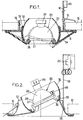
- the device shown diagrammatically in FIG. 1 comprises a support annular 10 in the form of a cylindrical shell provided with a rim flat 14 allowing the device to be pressed against a wall 12.
- the support is in two parts fixed to each other, for example by welding.
- elastic locking elements 16 carried by the support 10 allow to block it on the wall.
- these elastic elements are consisting of pincers springs, three in number for example, articulated on the support, having an arm provided to lean against the internal face of an opening 18 of the wall and an arm designed to lean against the rear face of the wall.
- the apparatus shown in Figure 1 is intended to receive a low-voltage miniature lamp 20 comprising a reflector 22 to which a supply socket 24 is attached, intended to be connected by flexible wires to a terminal block 26 fixed to the support 10.
- the reflector 22 is present under shape of a flared cap, often terminated by a rim or a support bulge 27.
- the apparatus comprises a ring 28 for receiving the lamp, on which the reflector 22 rests. means, not shown in Figure 1, allow secure the reflector to the ring.
- Connection means between the ring 28 and the support 10 include an intermediate piece 30 in the form of a ring spherical, the outer edge of which is integral with the ring.
- This intermediate piece constitutes a ball joint with a fold internal 32 of the rim 14.
- This internal fold is advantageously cone-shaped converging upwards.
- a flexible membrane 34 connects the outer edge of the intermediate piece 30 and / or the ring 28 at the periphery of the rim 14 of the support 10.
- the part outer of the membrane is folded around the periphery rim 14 and is glued to this periphery.
- the part internal of membrane 34 is also folded over and is bonded to the external surface of the intermediate piece.
- the membrane is initially manufactured so as to adapt to parts on which it is fixed. It is advantageously provided so that the area that connects the periphery of the support 10 to the ring is in tension and maintains the intermediate piece 30 pressed against the internal withdrawal 32.
- the elasticity of the membrane allows to orient at will the assembly constituted by the ring, the intermediate piece and the reflector.
- the coefficient of friction on the downturn 32 can be made sufficient for the intermediate piece retains the orientation given to it, despite the traction exerted by the membrane 34.
- the lighting fixture shown in Figure 2 (where the bodies corresponding to those of FIG. 1 are designated by the same reference number) is, unlike that of Figure 1, intended to be completely recessed.
- the support 10, in one piece, can be made of sheet metal folded, in light alloy molded, or even plastic. he still carries elastic locking elements, on the wall, constituted by a pincer spring, the branch of which internal is in abutment against the internal face of the support.
- the internal fold 32 flares inward this time. he still receives the support of the intermediate part 30, in the form spherical ring.
- the flexible membrane 34 also has an outer part folded over the peripheral part, substantially flat, support 10. This peripheral part can end with a folded spout designed to promote anchoring of the membrane.
- the inner part of the membrane is molded onto the intermediate piece 30.
- This intermediate piece may have internal circumferential projection 36 having gaps and allowing removable fixing the ring 28, for example by a bayonet type connection.
- This same ring can include a curved elastic blade 29 intended to resiliently enclose the reflector and to retain, allowing the reflector to be inserted and removed by lateral displacement, once the ring 28 is separated from its support.
- This arrangement can be of the kind described in the document FR-A-2 638 815.
- Other methods of retaining the reflector against the ring are possible, for example arms can be distributed circumferentially and having internal flange retaining pins 27.
- the terminal block 26 is mounted on a tab 38 stapled to the support 10.
- the cross section of this support 10 has a portion curve against which the membrane is applied when rotates the lamp from its centered position, as seen on the right of figure 2.
- the membrane remains in the volume delimited by the support, i.e. is recessed; it exerts on the intermediate piece 30 a effort which tends to keep it pressed against the fold internal 32.
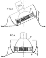
- Figure 3 shows a lighting fixture general similar to that of figure 2, but intended to receive a lamp 20 with parabolic glass reflector pressed, frequently designated by the abbreviation "PAR".
- the reflector is formed by the rear face itself of the lamp.
- the variant shown in FIG. 4 is intended to receive a halogen lamp, not shown.
- the device can then include a reflector 22, generally polished aluminum, with a flat end edge which bears against a shoulder of the ring 28.
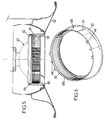
- Figure 5 shows yet another embodiment of the device, intended to receive a lamp of the so-called AR type, also having an integrated metal reflector.
- This lamp has a rim 40 intended to be retained on the ring 28. The latter can be locked so removable on the intermediate piece by means of the same like those already described in document FR-A-2 638 815 already mentioned.
- FIG. 6 shows, in perspective, a constitution possible ring usable in the embodiment of Figure 5.
- This ring is in the form of a ferrule cylindrical having a rim 36 bearing on the intermediate piece.
- the inner face of the ferrule has a shoulder 42 ledge support or bulge 40.
- Several fingers elastic 44 provided with internal lugs, integral with the ferrule, allow retaining the flange 40 pressing against the shoulder 42.
- Two bayonet-shaped grooves 46 are made in the external face of the shell and allow to introduce the lamp and the ring which carry it inside of the intermediate piece, then lock it in turning the ring a quarter turn. Thanks to this arrangement, the lamp can easily be replaced. We unlock the ring by rotating it and it is moved away from the wall. A sufficient length of flexible wires being provided between the socket and the terminal block (not shown in Figure 5). The lamp 20 can then be separated from the ring and replaced.
- the different components of the lighting fixture can be of various materials, in particular sheet metal or light alloy molded for the intermediate piece and support.
- the ring 28 will generally be made of light alloy mold.
- the flexible membrane 34 can be manufactured separately, then glued. It will be more frequently directly overmolded on the intermediate piece. When it includes a part which is glued on the intermediate part, it will generally be molded so as to have a cross section V-shaped corresponding to the resting form where it is shown for example in Figures 1, 4 and 5. Finally, the ring can be held by elastomer fingers making protrusion of the fold of the membrane, engaged in a simple groove of the ring.
Landscapes
- Engineering & Computer Science (AREA)
- General Engineering & Computer Science (AREA)
- Securing Globes, Refractors, Reflectors Or The Like (AREA)
- Fastening Of Light Sources Or Lamp Holders (AREA)
Applications Claiming Priority (2)
| Application Number | Priority Date | Filing Date | Title |
|---|---|---|---|
| FR9614681A FR2756613B1 (fr) | 1996-11-29 | 1996-11-29 | Appareil d'eclairage encastrable |
| FR9614681 | 1996-11-29 |
Publications (1)
| Publication Number | Publication Date |
|---|---|
| EP0845633A1 true EP0845633A1 (de) | 1998-06-03 |
Family
ID=9498185
Family Applications (1)
| Application Number | Title | Priority Date | Filing Date |
|---|---|---|---|
| EP97402876A Withdrawn EP0845633A1 (de) | 1996-11-29 | 1997-11-28 | Einbau- Beleuchtungseinrichtung |
Country Status (2)
| Country | Link |
|---|---|
| EP (1) | EP0845633A1 (de) |
| FR (1) | FR2756613B1 (de) |
Cited By (7)
| Publication number | Priority date | Publication date | Assignee | Title |
|---|---|---|---|---|
| DE10021546A1 (de) * | 2000-05-04 | 2001-11-29 | Hellux Leuchten | Befestigungsvorrichtung für Hängeleuchten |
| WO2005024297A1 (en) * | 2003-09-10 | 2005-03-17 | Targetti Sankey S.P.A. | Recessed type lighting fixture with device for quickly mounting and dismounting the lamp |
| EP1933082A4 (de) * | 2005-09-12 | 2009-03-25 | Liangju Wu | Wasserdichte universallampe |
| EP2899453A1 (de) * | 2014-01-22 | 2015-07-29 | Collingwood Lighting Limited | Leuchteinheit |
| GB2548388A (en) * | 2016-03-17 | 2017-09-20 | Orluna Led Tech Ltd | Light fitting |
| IT201700022297A1 (it) * | 2017-02-28 | 2018-08-28 | Reggiani Illuminazione | Dispositivo di illuminazione di tipo direzionabile. |
| EP3594559A1 (de) * | 2018-07-10 | 2020-01-15 | Collingwood Lighting Limited | Beleuchtungseinheit |
Citations (4)
| Publication number | Priority date | Publication date | Assignee | Title |
|---|---|---|---|---|
| US2554258A (en) * | 1949-01-22 | 1951-05-22 | Century Lighting Inc | Electric wall fixture having a universally mounted lamp |
| FR2638815A1 (fr) | 1988-11-04 | 1990-05-11 | Megalit | Appareil d'eclairage a reflecteur porte-lampe amovible |
| FR2669098A1 (fr) * | 1990-11-09 | 1992-05-15 | David Francis | Dispositif d'eclairage avec reflecteur et ampoule demontables et reglables. |
| DE4338841A1 (de) * | 1993-11-13 | 1995-05-18 | Axel Dickmann | Leuchte mit Lampengehäuse vorzugsweise für Niedervolt-Halogenlampen |
-
1996
- 1996-11-29 FR FR9614681A patent/FR2756613B1/fr not_active Expired - Fee Related
-
1997
- 1997-11-28 EP EP97402876A patent/EP0845633A1/de not_active Withdrawn
Patent Citations (4)
| Publication number | Priority date | Publication date | Assignee | Title |
|---|---|---|---|---|
| US2554258A (en) * | 1949-01-22 | 1951-05-22 | Century Lighting Inc | Electric wall fixture having a universally mounted lamp |
| FR2638815A1 (fr) | 1988-11-04 | 1990-05-11 | Megalit | Appareil d'eclairage a reflecteur porte-lampe amovible |
| FR2669098A1 (fr) * | 1990-11-09 | 1992-05-15 | David Francis | Dispositif d'eclairage avec reflecteur et ampoule demontables et reglables. |
| DE4338841A1 (de) * | 1993-11-13 | 1995-05-18 | Axel Dickmann | Leuchte mit Lampengehäuse vorzugsweise für Niedervolt-Halogenlampen |
Cited By (10)
| Publication number | Priority date | Publication date | Assignee | Title |
|---|---|---|---|---|
| DE10021546A1 (de) * | 2000-05-04 | 2001-11-29 | Hellux Leuchten | Befestigungsvorrichtung für Hängeleuchten |
| DE10021546C2 (de) * | 2000-05-04 | 2002-03-21 | Hellux Leuchten | Befestigungsvorrichtung für Hängeleuchten |
| WO2005024297A1 (en) * | 2003-09-10 | 2005-03-17 | Targetti Sankey S.P.A. | Recessed type lighting fixture with device for quickly mounting and dismounting the lamp |
| US7296907B2 (en) | 2003-09-10 | 2007-11-20 | Targetti Sankey S.P.A. | Lighting fixture |
| EP1933082A4 (de) * | 2005-09-12 | 2009-03-25 | Liangju Wu | Wasserdichte universallampe |
| EP2899453A1 (de) * | 2014-01-22 | 2015-07-29 | Collingwood Lighting Limited | Leuchteinheit |
| GB2548388A (en) * | 2016-03-17 | 2017-09-20 | Orluna Led Tech Ltd | Light fitting |
| IT201700022297A1 (it) * | 2017-02-28 | 2018-08-28 | Reggiani Illuminazione | Dispositivo di illuminazione di tipo direzionabile. |
| EP3366980A1 (de) * | 2017-02-28 | 2018-08-29 | Reggiani S.p.A. Illuminazione | Ausrichtbare beleuchtungsvorrichtung |
| EP3594559A1 (de) * | 2018-07-10 | 2020-01-15 | Collingwood Lighting Limited | Beleuchtungseinheit |
Also Published As
| Publication number | Publication date |
|---|---|
| FR2756613A1 (fr) | 1998-06-05 |
| FR2756613B1 (fr) | 1999-02-12 |
Similar Documents
| Publication | Publication Date | Title |
|---|---|---|
| EP1012483B1 (de) | Anordnung zum befestigen eines rohrförmigen elements auf einem teil der struktur einer kraftfahrzeugkarosserie | |
| FR2930319A1 (fr) | Applique lumineuse | |
| FR2836714A1 (fr) | Projecteur comprenant une lentille en verre et un support de lentille en matiere plastique et outil de surmoulage du support sur la lentille | |
| EP2699385B1 (de) | Halter für brillengläser | |
| FR2835321A1 (fr) | Monture d'objectif | |
| EP0845633A1 (de) | Einbau- Beleuchtungseinrichtung | |
| CA1265112A (fr) | Collet support pour abat-jour | |
| EP0286561B1 (de) | Schelle mit gelenkig gelagerter Spannschraube | |
| FR2638815A1 (fr) | Appareil d'eclairage a reflecteur porte-lampe amovible | |
| FR2828551A1 (fr) | Ensemble d'eclairage pour phare de vehicule | |
| FR2625847A1 (fr) | Dispositif de connexion magnetique entre une ampoule et sa douille | |
| FR2799528A1 (fr) | Dispositif d'eclairage pour vehicule a montage a baionnette | |
| FR2835595A1 (fr) | Douille de lampe pour projecteur de vehicule automobile, et reflecteur de projecteur destine a recevoir une telle douille de lampe. | |
| EP0810400B1 (de) | Scheinwerfer, insbesondere für Kraftfahrzeuge, mit einer verbesserten mechanischen Struktur | |
| FR2638817A1 (fr) | Dispositif de fixation d'un ensemble lampe-reflecteur dans une ouverture formee dans une paroi | |
| FR2790063A1 (fr) | Projecteur de vehicule automobile comportant des moyens perfectionnes de retenue de lampe | |
| EP0662584B1 (de) | Lampenfassung und Taschenlampe mit einer solchen Fassung | |
| FR2941285A3 (fr) | Lampe fluorescente dont le ballast et l'abat-jour reflechissant sont detachables l'un de l'autre. | |
| FR2649185A1 (fr) | Dispositif de montage et/ou de reglage en position d'une lampe dans un appareil d'eclairage ou de signalisation | |
| WO2001061243A1 (fr) | Luminaire comportant deux parties assemblees de facon etanche | |
| EP1151201B1 (de) | Vorrichtung zum befestigen eines zubehörs an einem träger und modulares system mit einer solchen vorrichtung | |
| EP3260762B1 (de) | Lichtdiffusor | |
| FR3041567A1 (fr) | Assemblage d'une roue et d'un enjoliveur | |
| EP1467147A1 (de) | Anordnung zur Halterung einer Lampe an einem Reflektor und Kfz-Scheinwerfer mit einer solchen Anordnung | |
| FR2892161A1 (fr) | Dispositif de solidarisation d'un ensemble constitue de tiges et d'un bras dans un plan perpendiculaire aux tiges et procede de solidarisation des tiges et du bras |
Legal Events
| Date | Code | Title | Description |
|---|---|---|---|
| PUAI | Public reference made under article 153(3) epc to a published international application that has entered the european phase |
Free format text: ORIGINAL CODE: 0009012 |
|
| AK | Designated contracting states |
Kind code of ref document: A1 Designated state(s): AT BE CH DE DK ES FI FR GB GR IE IT LI LU MC NL PT SE |
|
| AX | Request for extension of the european patent |
Free format text: AL;LT;LV;MK;RO;SI |
|
| AKX | Designation fees paid | ||
| RBV | Designated contracting states (corrected) | ||
| STAA | Information on the status of an ep patent application or granted ep patent |
Free format text: STATUS: THE APPLICATION IS DEEMED TO BE WITHDRAWN |
|
| 18D | Application deemed to be withdrawn |
Effective date: 19981204 |