EP0845642A2 - Système frigorifique utilisant un compresseur à fonctionnement mono- ou multi-étagé avec contrÔle de capacité - Google Patents
Système frigorifique utilisant un compresseur à fonctionnement mono- ou multi-étagé avec contrÔle de capacité Download PDFInfo
- Publication number
- EP0845642A2 EP0845642A2 EP97630079A EP97630079A EP0845642A2 EP 0845642 A2 EP0845642 A2 EP 0845642A2 EP 97630079 A EP97630079 A EP 97630079A EP 97630079 A EP97630079 A EP 97630079A EP 0845642 A2 EP0845642 A2 EP 0845642A2
- Authority
- EP
- European Patent Office
- Prior art keywords
- stage
- compressor
- unloading
- refrigeration system
- banks
- Prior art date
- Legal status (The legal status is an assumption and is not a legal conclusion. Google has not performed a legal analysis and makes no representation as to the accuracy of the status listed.)
- Granted
Links
Images

Classifications
-
- F—MECHANICAL ENGINEERING; LIGHTING; HEATING; WEAPONS; BLASTING
- F25—REFRIGERATION OR COOLING; COMBINED HEATING AND REFRIGERATION SYSTEMS; HEAT PUMP SYSTEMS; MANUFACTURE OR STORAGE OF ICE; LIQUEFACTION SOLIDIFICATION OF GASES
- F25B—REFRIGERATION MACHINES, PLANTS OR SYSTEMS; COMBINED HEATING AND REFRIGERATION SYSTEMS; HEAT PUMP SYSTEMS
- F25B1/00—Compression machines, plants or systems with non-reversible cycle
-
- F—MECHANICAL ENGINEERING; LIGHTING; HEATING; WEAPONS; BLASTING
- F25—REFRIGERATION OR COOLING; COMBINED HEATING AND REFRIGERATION SYSTEMS; HEAT PUMP SYSTEMS; MANUFACTURE OR STORAGE OF ICE; LIQUEFACTION SOLIDIFICATION OF GASES
- F25B—REFRIGERATION MACHINES, PLANTS OR SYSTEMS; COMBINED HEATING AND REFRIGERATION SYSTEMS; HEAT PUMP SYSTEMS
- F25B1/00—Compression machines, plants or systems with non-reversible cycle
- F25B1/10—Compression machines, plants or systems with non-reversible cycle with multi-stage compression
-
- F—MECHANICAL ENGINEERING; LIGHTING; HEATING; WEAPONS; BLASTING
- F04—POSITIVE - DISPLACEMENT MACHINES FOR LIQUIDS; PUMPS FOR LIQUIDS OR ELASTIC FLUIDS
- F04B—POSITIVE-DISPLACEMENT MACHINES FOR LIQUIDS; PUMPS
- F04B49/00—Control, e.g. of pump delivery, or pump pressure of, or safety measures for, machines, pumps, or pumping installations, not otherwise provided for, or of interest apart from, groups F04B1/00 - F04B47/00
-
- F—MECHANICAL ENGINEERING; LIGHTING; HEATING; WEAPONS; BLASTING
- F04—POSITIVE - DISPLACEMENT MACHINES FOR LIQUIDS; PUMPS FOR LIQUIDS OR ELASTIC FLUIDS
- F04B—POSITIVE-DISPLACEMENT MACHINES FOR LIQUIDS; PUMPS
- F04B49/00—Control, e.g. of pump delivery, or pump pressure of, or safety measures for, machines, pumps, or pumping installations, not otherwise provided for, or of interest apart from, groups F04B1/00 - F04B47/00
- F04B49/06—Control using electricity
- F04B49/065—Control using electricity and making use of computers
-
- F—MECHANICAL ENGINEERING; LIGHTING; HEATING; WEAPONS; BLASTING
- F25—REFRIGERATION OR COOLING; COMBINED HEATING AND REFRIGERATION SYSTEMS; HEAT PUMP SYSTEMS; MANUFACTURE OR STORAGE OF ICE; LIQUEFACTION SOLIDIFICATION OF GASES
- F25B—REFRIGERATION MACHINES, PLANTS OR SYSTEMS; COMBINED HEATING AND REFRIGERATION SYSTEMS; HEAT PUMP SYSTEMS
- F25B49/00—Arrangement or mounting of control or safety devices
- F25B49/02—Arrangement or mounting of control or safety devices for compression type machines, plants or systems
- F25B49/022—Compressor control arrangements
-
- F—MECHANICAL ENGINEERING; LIGHTING; HEATING; WEAPONS; BLASTING
- F04—POSITIVE - DISPLACEMENT MACHINES FOR LIQUIDS; PUMPS FOR LIQUIDS OR ELASTIC FLUIDS
- F04B—POSITIVE-DISPLACEMENT MACHINES FOR LIQUIDS; PUMPS
- F04B2201/00—Pump parameters
- F04B2201/08—Cylinder or housing parameters
- F04B2201/0807—Number of working cylinders
-
- F—MECHANICAL ENGINEERING; LIGHTING; HEATING; WEAPONS; BLASTING
- F25—REFRIGERATION OR COOLING; COMBINED HEATING AND REFRIGERATION SYSTEMS; HEAT PUMP SYSTEMS; MANUFACTURE OR STORAGE OF ICE; LIQUEFACTION SOLIDIFICATION OF GASES
- F25B—REFRIGERATION MACHINES, PLANTS OR SYSTEMS; COMBINED HEATING AND REFRIGERATION SYSTEMS; HEAT PUMP SYSTEMS
- F25B2400/00—Component parts or details not otherwise provided for in this subclass
- F25B2400/07—Details of compressors or related parts
- F25B2400/075—Details of compressors or related parts with parallel compressors
-
- F—MECHANICAL ENGINEERING; LIGHTING; HEATING; WEAPONS; BLASTING
- F25—REFRIGERATION OR COOLING; COMBINED HEATING AND REFRIGERATION SYSTEMS; HEAT PUMP SYSTEMS; MANUFACTURE OR STORAGE OF ICE; LIQUEFACTION SOLIDIFICATION OF GASES
- F25B—REFRIGERATION MACHINES, PLANTS OR SYSTEMS; COMBINED HEATING AND REFRIGERATION SYSTEMS; HEAT PUMP SYSTEMS
- F25B2400/00—Component parts or details not otherwise provided for in this subclass
- F25B2400/13—Economisers
Definitions
- Transport refrigeration can have a load requiring a temperature of -20°F in the case of ice cream, 0°F in the case of some frozen foods and 40°F in the case of flowers and fresh fruit and vegetables.
- a trailer may also have more than one compartment with loads having different temperature requirements.
- some cargo such as fruit, vegetables and flowers
- tight temperature control is necessary to avoid premature ripening or blooming.
- the ambient temperatures encountered may range from -20°F, or below, to 110°F, or more. Because of the wide range of ambient temperatures that can be encountered on a single trip as well as the widely varying load temperature requirements, there can be a wide range in refrigeration capacity requirements.
- Multi-stage compressors are desired for transport refrigeration applications because they offer improved refrigerating capacity over traditional single-stage compressors for a modest cost premium.
- Currently available multi-stage compressor technology is difficult for the end user to apply because it requires a substantial number of external valves and pipes and has many application limitations that are necessary for the compressors to operate reliably.
- Japanese reference 53-133,257 discloses a multi-compressor arrangement.
- Commonly assigned U.S. Patent Number 5,577,390 relates to multi-stage compressor operation and commonly assigned U.S. Application Serial No. 08/360,483, now U.S. Patent 5,577,390 relates to capacity control in a multi-stage compressor.
- patents 4,938,029, 4,986,084 and 5,062,274 disclose reduced capacity operation responsive to load requirements while U.S. Patent 5,016,447 discloses a two-stage compressor with interstage cooling.
- the intermediate pressure gas can be routed through the crankcase sump. Utilizing this approach for low temperature applications works quite well to increase the efficiency, however, in medium and high temperature applications several complications arise. Higher crankcase pressures produce a lower effective oil viscosity, increased thrust washer loads, and increased bearing loads.
- a compressor having plural banks of cylinders can be operated multi-stage during low temperature operation and with a single stage or plural parallel single stages for medium and high temperature operation. Additionally, economizer operation can be employed when the compressor is in two-stage operation. Switching between single stage and multi-stage operation is under the control of a microprocessor in response to the sensed suction or crankcase sump pressure or to the box temperature in the case of load pulldown. Multi-stage operation provides increased capacity through the use of an economizer and lower pressure differences across each stage. Reduced capacity operation can be achieved by bypassing the first stage back to suction, by employing suction cutoff in the first stage, by bypassing the entire first stage, or by bypassing the high stage.
- the two outer or end banks would be designated as low stage banks.
- One of the low stage banks (LS-1) is equipped with a cylinder head configuration allowing the introduction of economizer gas into the discharge side of the cylinder head.
- the other low stage bank (LS-2) would be equipped with a standard suction cutoff unloader head.
- the center bank of the compressor would be designated as the high stage (HS) and is equipped with a cylinder head that allows the discharge gas from LS-2 to cross over to the suction side of HS internal to HS.
- a valve plate that blocks the flow of suction gas from the crankcase into the suction side of HS is utilized.
- the present invention simplifies the application and control of a multi-stage compressor by routing the suction gas directly into the crankcase and internalizing the routing of the mid-stage gas.
- the only piping connections to the compressor would be the traditional suction and discharge connections and an additional connection for introducing economizer gas.
- the only additional system components required, as compared to a normal single stage system. would be an economizer, an economizer expansion valve, an economizer liquid line solenoid valve and bypass line valve(s).
- the steps are: single stage with two cylinders/one bank, LS-1, loaded; single stage with both LS-1 and LS-2 loaded; modified multi-stage operation with the two cylinders of one low stage bank, LS-1, pumping into the high stage bank HS, with and without the economizer being active; and traditional multi-stage operation with LS-1 and LS-2 pumping into HS with and without the economizer being active.
- the suction or crankcase sump pressure and/or the box or zone temperature is sensed and, responsive thereto, the compressor is operated in either a multi-stage or single stage mode.
- Single stage operation may be as plural banks in parallel or by unloading either the first stage or second stage in multi-stage operation.
- Economizer operation may be employed in multi-stage operation.
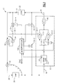
- Microproccssor 100 exerts overall control in the refrigeration system 10 of Figure 1.
- Microprocessor 100 receives zone inputs indicating cooling requirements and, responsive thereto, starts and/or engages the internal combustion engine (not illustrated) driving compressor 12 in the case of a transport refrigeration system and provides power to the motor driving compressor 12 in the case of a stationary/commercial refrigeration system.
- Pressure sensor 40 senses the suction pressure in crankcase 14 which is a primary indicator of the operation of compressor 12 and which indicates the need to load compressor 12 when the sensed pressure is above a predetermined set point. Responsive to the pressure sensed by pressure sensor 40 and to the zone inputs, microprocessor 100 controls the capacity of compressor 12 and thereby system 10 by controlling solenoid valves SV-1 through SV-4.
- SV-1 is normally open and SV-2 through SV-4 are normally closed. Only one of valves SV-2 through SV-4 can be open at any time. Valves SV-2 and SV-3 and the lines in which they are located can be considered as redundant or alternative and, normally, only one would be present in a system.
- Pistons are reciprocatably driven by the motor (not illustrated) through a crankshaft (not illustrated).
- the crankshaft is located in crankcase 14 which has an oil sump located at the bottom thereof.
- Compressor 12 has a suction line 16 and a discharge line 18 which are connected, respectively, to the evaporator 20 and condenser 22 of refrigeration system 10.
- Economizer 30 and thermal expansion device, TXV, 32 are serially located between condenser 22 and evaporator 20.
- Suction line 16 includes crankcase 14 and branches into line 16-1 which feeds the cylinders of the first low stage bank LS-1 and line 16-2 which contains suction cutoff valve SV-1 and feeds the cylinders of the second low stage bank LS-2.
- the first and second banks, LS-1 and LS-2 discharge hot, intermediate pressure refrigerant gas into plenum M which serves as the suction plenum for high stage HS.
- the hot high pressure gas discharged from high stage HS is supplied at discharge pressure, P D , via discharge line 18 to condenser 22.
- the hot refrigerant gas gives up heat to the condenser air thereby cooling the compressed gas and changing the state of the refrigerant from a gas to a liquid.
- solenoid valve SV-4 closed, liquid refrigerant flows from condenser 22 via liquid line 24 and inoperative economizer 30 to thermostatic expansion valve, TXV, 32.
- solenoid valve SV-4 By opening solenoid valve SV-4, microprocessor 100 diverts a portion of the liquid refrigerant from liquid line 24 into branch line 24-1 permitting flow through, and thereby enabling, economizer 30 under the control of TXV 34.
- servo valve SV-4 and TXV 34 open, expanded refrigerant is supplied at economizer prcssure, P ECON , via line 24-1 to plenum M which represents the discharge plenum of banks LS-1 and LS-2 and the suction plenum of bank HS.
- economizer prcssure, P ECON With SV-1 and SV-4 open maximum capacity is achieved. Closing solenoid valve SV-1 and thereby unloading bank LS-2 by suction cutoff reduces the total capacity by reducing the system mass flow independent of whether there is economizer operation.
- SV-4 With SV-4 closed, the economizer is disabled and reduced capacity two-stage operation is achieved. Further capacity reduction can be obtained by closing solenoid valve SV-1 and thereby unloading bank LS-2 by suction cutoff. Reduced single stage operation can be achieved by opening SV-2 to bypass the first stage so that bank HS is doing all of the pumping or by opening SV-3 to bypass the second stage. With SV-3 open both banks LS-1 and LS-2 can be pumping or LS-2 can be unloaded by closing SV-1. As noted above, SV-2 and SV-3 are generally alternative.
- FIG. 2 it will be noted that line 16-1 feeds suction chamber, L, of LS-1 and line 16-2 feeds suction chamber, L, of LS-2.
- Chambers M which are in fluid communication with each other, represent the discharge chambers of LS-1 and LS-2 and the suction chamber of HS.
- Chamber M of LS-2 is in fluid communication with chamber M of HS via a passage 50-4 through chamber H in cylinder head 50 of HS.
- partition 50-1 divides cylinder head 50 into chamber M and chamber H.
- the valve plate (not illustrated) coacts with cylinder head 50 to define chambers M and H of HS.
- inlet ports 50-2 and 50-3 are provided. Ports 50-2 and 50-3 register with passage 50-4 and corresponding ports in the valve plate (not illustrated) of HS which provide fluid communication with chamber M of LS-2. Accordingly, a fluid path exists from chamber M of LS-2 to chamber M of HS serially including the ports in the valve plate of HS, ports 50-2 and 50-3, and passage 50-4 which leads to chamber M of HS. As shown schematically in Figure 2, chamber M of LS-1 is connected via a fluid path with chamber M of HS but it does not require a special modification of cylinder head 50 such as passage 50-4.
Landscapes
- Engineering & Computer Science (AREA)
- Mechanical Engineering (AREA)
- General Engineering & Computer Science (AREA)
- Physics & Mathematics (AREA)
- Thermal Sciences (AREA)
- Computer Hardware Design (AREA)
- Compressors, Vaccum Pumps And Other Relevant Systems (AREA)
- Control Of Positive-Displacement Pumps (AREA)
- Supercharger (AREA)
- Compression-Type Refrigeration Machines With Reversible Cycles (AREA)
- Dc-Dc Converters (AREA)
- Applications Or Details Of Rotary Compressors (AREA)
- Compressor (AREA)
- Air Conditioning Control Device (AREA)
- Output Control And Ontrol Of Special Type Engine (AREA)
Applications Claiming Priority (2)
| Application Number | Priority Date | Filing Date | Title |
|---|---|---|---|
| US758837 | 1996-12-02 | ||
| US08/758,837 US5768901A (en) | 1996-12-02 | 1996-12-02 | Refrigerating system employing a compressor for single or multi-stage operation with capacity control |
Publications (3)
| Publication Number | Publication Date |
|---|---|
| EP0845642A2 true EP0845642A2 (fr) | 1998-06-03 |
| EP0845642A3 EP0845642A3 (fr) | 1999-12-01 |
| EP0845642B1 EP0845642B1 (fr) | 2003-05-21 |
Family
ID=25053302
Family Applications (1)
| Application Number | Title | Priority Date | Filing Date |
|---|---|---|---|
| EP97630079A Expired - Lifetime EP0845642B1 (fr) | 1996-12-02 | 1997-11-14 | Système frigorifique utilisant un compresseur à fonctionnement mono- ou multi-étagé avec contrôle de capacité |
Country Status (11)
| Country | Link |
|---|---|
| US (1) | US5768901A (fr) |
| EP (1) | EP0845642B1 (fr) |
| JP (1) | JP3053379B2 (fr) |
| KR (1) | KR100409174B1 (fr) |
| CN (1) | CN1109864C (fr) |
| AR (1) | AR008924A1 (fr) |
| BR (1) | BR9706031A (fr) |
| DE (1) | DE69722146T2 (fr) |
| MX (1) | MX9709349A (fr) |
| MY (1) | MY119339A (fr) |
| TW (1) | TW376428B (fr) |
Cited By (13)
| Publication number | Priority date | Publication date | Assignee | Title |
|---|---|---|---|---|
| EP0981033A3 (fr) * | 1998-08-20 | 2001-02-28 | Carrier Corporation | Procédé pour faire fonctionner un système frigorifique en régime permanent |
| WO2003014637A3 (fr) * | 2001-08-09 | 2003-04-17 | Albert Robert Lowes | Installation de refrigeration |
| EP1357338A1 (fr) * | 2002-04-03 | 2003-10-29 | Jean-Paul Arpin | Installation frigorifique basse température notamment pour la congélation, la surgélation et le stockage de produits, tels que des produits alimentaires |
| WO2005008148A1 (fr) * | 2003-07-14 | 2005-01-27 | Carrier Corporation | Systeme de compression de fluide frigorigene a sous-refroidissement selectif |
| WO2006087075A1 (fr) * | 2005-02-17 | 2006-08-24 | Bitzer Kühlmaschinenbau Gmbh | Appareil frigorifique |
| WO2008142714A1 (fr) * | 2007-05-22 | 2008-11-27 | Angelantoni Industrie Spa | Dispositif de réfrigération et procédé pour faire circuler un fluide de réfrigération associé à celui-ci |
| WO2010033589A2 (fr) | 2008-09-18 | 2010-03-25 | Carrier Corporation | Compresseur alternatif a plusieurs etages |
| RU2432531C2 (ru) * | 2007-05-22 | 2011-10-27 | Анджелантони Индустрие Спа | Холодильное устройство и способ циркуляции в нем охлаждающей текучей среды |
| EP2008039A4 (fr) * | 2006-03-27 | 2011-12-14 | Carrier Corp | Système réfrigérant avec circuits économiseurs étagés en parallèle à sortie transférée en pression interétage d'un compresseur principal |
| EP2326838A4 (fr) * | 2008-08-12 | 2015-10-07 | Carrier Corp | Soupape à impulsion spécialisée pour cylindre de compresseur |
| EP2456980A4 (fr) * | 2009-07-20 | 2016-02-24 | Carrier Corp | Soupape de décompression à coupure d'aspiration pour commande de capacité de compresseur |
| WO2016182998A1 (fr) * | 2015-05-13 | 2016-11-17 | Carrier Corporation | Compresseur à va-et-vient économisé |
| US10107536B2 (en) | 2009-12-18 | 2018-10-23 | Carrier Corporation | Transport refrigeration system and methods for same to address dynamic conditions |
Families Citing this family (34)
| Publication number | Priority date | Publication date | Assignee | Title |
|---|---|---|---|---|
| US6058729A (en) * | 1998-07-02 | 2000-05-09 | Carrier Corporation | Method of optimizing cooling capacity, energy efficiency and reliability of a refrigeration system during temperature pull down |
| US6238188B1 (en) * | 1998-08-17 | 2001-05-29 | Carrier Corporation | Compressor control at voltage and frequency extremes of power supply |
| US6321550B1 (en) | 1999-04-21 | 2001-11-27 | Carrier Corporation | Start up control for a transport refrigeration unit with synchronous generator power system |
| US6718781B2 (en) | 2001-07-11 | 2004-04-13 | Thermo King Corporation | Refrigeration unit apparatus and method |
| US6938438B2 (en) * | 2003-04-21 | 2005-09-06 | Carrier Corporation | Vapor compression system with bypass/economizer circuits |
| DE10321771C5 (de) * | 2003-05-15 | 2017-01-19 | Continental Teves Ag & Co. Ohg | Verfahren zur Leistungsbegrenzung eines mehrstufigen Kompressor und Kompressor zur Durchführung des Verfahrens |
| US6928828B1 (en) * | 2004-01-22 | 2005-08-16 | Carrier Corporation | Tandem compressors with economized operation |
| US6955058B2 (en) * | 2004-01-30 | 2005-10-18 | Carrier Corporation | Refrigerant cycle with tandem economized and conventional compressors |
| US7475565B2 (en) * | 2004-08-27 | 2009-01-13 | Zero Zone, Inc. | Refrigeration system including a side-load sub-cooler |
| US7409833B2 (en) * | 2005-03-10 | 2008-08-12 | Sunpower, Inc. | Dual mode compressor with automatic compression ratio adjustment for adapting to multiple operating conditions |
| WO2006130137A2 (fr) * | 2005-05-31 | 2006-12-07 | Carrier Corporation | Limitation dans une ligne d'injection de vapeur |
| US7204099B2 (en) * | 2005-06-13 | 2007-04-17 | Carrier Corporation | Refrigerant system with vapor injection and liquid injection through separate passages |
| US7251947B2 (en) * | 2005-08-09 | 2007-08-07 | Carrier Corporation | Refrigerant system with suction line restrictor for capacity correction |
| CA2626331A1 (fr) | 2005-10-18 | 2007-04-26 | Carrier Corporation | Systeme de compression de vapeur refrigerante dote d'un cycle economiseur permettant de chauffer de l'eau |
| CN100451467C (zh) * | 2006-01-23 | 2009-01-14 | 蒋华 | 一种组合式空气处理方法和装置 |
| WO2007111594A1 (fr) * | 2006-03-27 | 2007-10-04 | Carrier Corporation | Système de réfrigération avec circuits d'économiseur étagés en parallèle et compresseur principal à un ou deux étages |
| KR101492115B1 (ko) | 2006-10-26 | 2015-02-10 | 존슨 컨트롤스 테크놀러지 컴퍼니 | 이코노마이즈드 냉동 시스템 |
| US8312737B2 (en) * | 2006-12-29 | 2012-11-20 | Carrier Corporation | Economizer heat exchanger |
| CN101688695B (zh) * | 2007-04-23 | 2014-07-23 | 开利公司 | 带增强器回路的co2制冷剂系统 |
| AU2009228000B2 (en) * | 2008-09-19 | 2013-03-07 | Woodside Energy Limited | Mixed refrigerant compression circuit |
| US9238398B2 (en) * | 2008-09-25 | 2016-01-19 | B/E Aerospace, Inc. | Refrigeration systems and methods for connection with a vehicle's liquid cooling system |
| US20110162396A1 (en) * | 2008-09-29 | 2011-07-07 | Carrier Corporation | Capacity boosting during pulldown |
| US9677788B2 (en) * | 2009-06-12 | 2017-06-13 | Carrier Corporation | Refrigerant system with multiple load modes |
| CN101713599B (zh) * | 2009-11-09 | 2012-06-27 | 刘雄 | 空调热泵装置 |
| CN102022851B (zh) * | 2010-12-22 | 2012-05-23 | 天津商业大学 | 双级压缩制冷系统 |
| US10378533B2 (en) * | 2011-12-06 | 2019-08-13 | Bitzer Us, Inc. | Control for compressor unloading system |
| US10724462B2 (en) * | 2012-04-20 | 2020-07-28 | General Electric Company | System and method for a compressor |
| CN102748900B (zh) * | 2012-07-24 | 2015-03-11 | 上海伯涵热能科技有限公司 | 单双级压缩顺序使用的热泵、热泵空调及热泵热水机组 |
| CN103511266A (zh) * | 2013-04-09 | 2014-01-15 | 广东美芝制冷设备有限公司 | 旋转式压缩机 |
| CN103954064B (zh) * | 2014-04-15 | 2016-04-13 | 珠海格力电器股份有限公司 | 制冷装置 |
| CN104697222A (zh) * | 2015-03-06 | 2015-06-10 | 浪潮电子信息产业股份有限公司 | 一种高发热量的云服务器低温试验系统 |
| CN108662799A (zh) | 2017-03-31 | 2018-10-16 | 开利公司 | 多级制冷系统及其控制方法 |
| CN111486609B (zh) * | 2020-04-02 | 2021-10-08 | 珠海格力节能环保制冷技术研究中心有限公司 | 一种空调系统和控制方法 |
| DE102024100767A1 (de) | 2024-01-11 | 2025-07-17 | Konvekta Aktiengesellschaft | Flexible Verdichtungseinrichtung und Kältemittelkreislauf damit sowie Verfahren dazu |
Citations (6)
| Publication number | Priority date | Publication date | Assignee | Title |
|---|---|---|---|---|
| JPS53133257A (en) | 1977-04-27 | 1978-11-20 | Ube Ind Ltd | Flame-retardant polyamide composition |
| US4938029A (en) | 1989-07-03 | 1990-07-03 | Carrier Corporation | Unloading system for two-stage compressors |
| US4986084A (en) | 1988-06-20 | 1991-01-22 | Carrier Corporation | Quench expansion valve refrigeration circuit |
| US5016447A (en) | 1990-05-02 | 1991-05-21 | Carrier Corporation | Oil return for a two-stage compressor having interstage cooling |
| US5062274A (en) | 1989-07-03 | 1991-11-05 | Carrier Corporation | Unloading system for two compressors |
| US5577390A (en) | 1994-11-14 | 1996-11-26 | Carrier Corporation | Compressor for single or multi-stage operation |
Family Cites Families (3)
| Publication number | Priority date | Publication date | Assignee | Title |
|---|---|---|---|---|
| US3447335A (en) * | 1967-09-22 | 1969-06-03 | John D Ruff | Variable capacity centrifugal heat pump |
| US4947655A (en) * | 1984-01-11 | 1990-08-14 | Copeland Corporation | Refrigeration system |
| US5626027A (en) * | 1994-12-21 | 1997-05-06 | Carrier Corporation | Capacity control for multi-stage compressors |
-
1996
- 1996-12-02 US US08/758,837 patent/US5768901A/en not_active Expired - Lifetime
-
1997
- 1997-11-14 DE DE69722146T patent/DE69722146T2/de not_active Expired - Lifetime
- 1997-11-14 EP EP97630079A patent/EP0845642B1/fr not_active Expired - Lifetime
- 1997-11-19 MY MYPI97005568A patent/MY119339A/en unknown
- 1997-11-20 TW TW086117371A patent/TW376428B/zh active
- 1997-11-27 BR BR9706031A patent/BR9706031A/pt not_active IP Right Cessation
- 1997-11-28 JP JP9327300A patent/JP3053379B2/ja not_active Expired - Lifetime
- 1997-12-01 KR KR1019970065001A patent/KR100409174B1/ko not_active Expired - Fee Related
- 1997-12-01 MX MX9709349A patent/MX9709349A/es not_active IP Right Cessation
- 1997-12-02 AR ARP970105668A patent/AR008924A1/es active IP Right Grant
- 1997-12-02 CN CN97126038A patent/CN1109864C/zh not_active Expired - Fee Related
Patent Citations (6)
| Publication number | Priority date | Publication date | Assignee | Title |
|---|---|---|---|---|
| JPS53133257A (en) | 1977-04-27 | 1978-11-20 | Ube Ind Ltd | Flame-retardant polyamide composition |
| US4986084A (en) | 1988-06-20 | 1991-01-22 | Carrier Corporation | Quench expansion valve refrigeration circuit |
| US4938029A (en) | 1989-07-03 | 1990-07-03 | Carrier Corporation | Unloading system for two-stage compressors |
| US5062274A (en) | 1989-07-03 | 1991-11-05 | Carrier Corporation | Unloading system for two compressors |
| US5016447A (en) | 1990-05-02 | 1991-05-21 | Carrier Corporation | Oil return for a two-stage compressor having interstage cooling |
| US5577390A (en) | 1994-11-14 | 1996-11-26 | Carrier Corporation | Compressor for single or multi-stage operation |
Cited By (21)
| Publication number | Priority date | Publication date | Assignee | Title |
|---|---|---|---|---|
| EP0981033A3 (fr) * | 1998-08-20 | 2001-02-28 | Carrier Corporation | Procédé pour faire fonctionner un système frigorifique en régime permanent |
| WO2003014637A3 (fr) * | 2001-08-09 | 2003-04-17 | Albert Robert Lowes | Installation de refrigeration |
| EP1357338A1 (fr) * | 2002-04-03 | 2003-10-29 | Jean-Paul Arpin | Installation frigorifique basse température notamment pour la congélation, la surgélation et le stockage de produits, tels que des produits alimentaires |
| WO2005008148A1 (fr) * | 2003-07-14 | 2005-01-27 | Carrier Corporation | Systeme de compression de fluide frigorigene a sous-refroidissement selectif |
| WO2006087075A1 (fr) * | 2005-02-17 | 2006-08-24 | Bitzer Kühlmaschinenbau Gmbh | Appareil frigorifique |
| US7451617B2 (en) | 2005-02-17 | 2008-11-18 | Bitzer Kuhlmaschinenbau Gmbh | Refrigeration system |
| EP2008039A4 (fr) * | 2006-03-27 | 2011-12-14 | Carrier Corp | Système réfrigérant avec circuits économiseurs étagés en parallèle à sortie transférée en pression interétage d'un compresseur principal |
| US8322150B2 (en) | 2006-03-27 | 2012-12-04 | Carrier Corporation | Refrigerating system with parallel staged economizer circuits discharging to interstage pressures of a main compressor |
| JP2010528250A (ja) * | 2007-05-22 | 2010-08-19 | アンジェラントーニ インダストリエ エスピーエー | 冷却デバイス、および冷却流体を循環させるための方法 |
| RU2432531C2 (ru) * | 2007-05-22 | 2011-10-27 | Анджелантони Индустрие Спа | Холодильное устройство и способ циркуляции в нем охлаждающей текучей среды |
| WO2008142714A1 (fr) * | 2007-05-22 | 2008-11-27 | Angelantoni Industrie Spa | Dispositif de réfrigération et procédé pour faire circuler un fluide de réfrigération associé à celui-ci |
| US8505317B2 (en) | 2007-05-22 | 2013-08-13 | Angelantoni Life Science SRI | Refrigerating device and method for circulating a refrigerating fluid associated with it |
| EP2326838A4 (fr) * | 2008-08-12 | 2015-10-07 | Carrier Corp | Soupape à impulsion spécialisée pour cylindre de compresseur |
| EP2331817A4 (fr) * | 2008-09-18 | 2015-05-06 | Carrier Corp | Compresseur alternatif a plusieurs etages |
| WO2010033589A2 (fr) | 2008-09-18 | 2010-03-25 | Carrier Corporation | Compresseur alternatif a plusieurs etages |
| US9382906B2 (en) | 2008-09-18 | 2016-07-05 | Carrier Corporation | Multi-stage reciprocating compressor |
| EP2456980A4 (fr) * | 2009-07-20 | 2016-02-24 | Carrier Corp | Soupape de décompression à coupure d'aspiration pour commande de capacité de compresseur |
| US10107536B2 (en) | 2009-12-18 | 2018-10-23 | Carrier Corporation | Transport refrigeration system and methods for same to address dynamic conditions |
| WO2016182998A1 (fr) * | 2015-05-13 | 2016-11-17 | Carrier Corporation | Compresseur à va-et-vient économisé |
| US10253766B2 (en) | 2015-05-13 | 2019-04-09 | Carrier Corporation | Economized reciprocating compressor |
| EP3295029B1 (fr) | 2015-05-13 | 2019-07-03 | Carrier Corporation | Compresseur à va-et-vient économisé |
Also Published As
| Publication number | Publication date |
|---|---|
| BR9706031A (pt) | 1999-08-03 |
| KR100409174B1 (ko) | 2004-03-20 |
| US5768901A (en) | 1998-06-23 |
| JP3053379B2 (ja) | 2000-06-19 |
| CN1109864C (zh) | 2003-05-28 |
| JPH10170083A (ja) | 1998-06-26 |
| CN1188219A (zh) | 1998-07-22 |
| KR19980063651A (ko) | 1998-10-07 |
| MX9709349A (es) | 1998-06-30 |
| AR008924A1 (es) | 2000-02-23 |
| MY119339A (en) | 2005-05-31 |
| EP0845642A3 (fr) | 1999-12-01 |
| EP0845642B1 (fr) | 2003-05-21 |
| TW376428B (en) | 1999-12-11 |
| DE69722146D1 (de) | 2003-06-26 |
| DE69722146T2 (de) | 2004-04-08 |
Similar Documents
| Publication | Publication Date | Title |
|---|---|---|
| US5768901A (en) | Refrigerating system employing a compressor for single or multi-stage operation with capacity control | |
| US5577390A (en) | Compressor for single or multi-stage operation | |
| US5626027A (en) | Capacity control for multi-stage compressors | |
| US5582022A (en) | Economizer control for two-stage compressor systems | |
| US6820434B1 (en) | Refrigerant compression system with selective subcooling | |
| US7213405B2 (en) | Two-stage linear compressor | |
| US6938430B2 (en) | Refrigerating device | |
| US7992408B2 (en) | Compressor | |
| JPH0833251B2 (ja) | 冷却装置及び冷却方法 | |
| WO2005094401A2 (fr) | Systeme de refroidissement a temperatures multiples | |
| WO2009048464A1 (fr) | Compresseurs en tandem de types différents | |
| JP3152454B2 (ja) | 二段圧縮式冷凍装置 | |
| US4538421A (en) | Refrigerating system | |
| JPH073247Y2 (ja) | 2軸2段冷凍装置 | |
| US20240353152A1 (en) | Two-stage refrigeration system | |
| JP2997598B2 (ja) | 多機能ヒートポンプシステム | |
| JPS6029555A (ja) | 2シリンダ回転式圧縮機の冷凍サイクル | |
| JPH06281271A (ja) | 冷凍装置 | |
| JP2003222420A (ja) | 冷凍機 | |
| HK1138353A (en) | Refrigerant system with economizer, intercooler and multi-stage compressor | |
| JPS58156161A (ja) | 冷凍装置の蒸発圧力制御装置 | |
| JPH0370154B2 (fr) | ||
| HK1115430B (en) | Multi-temperature cooling system with unloading |
Legal Events
| Date | Code | Title | Description |
|---|---|---|---|
| PUAI | Public reference made under article 153(3) epc to a published international application that has entered the european phase |
Free format text: ORIGINAL CODE: 0009012 |
|
| AK | Designated contracting states |
Kind code of ref document: A2 Designated state(s): DE FR IT SE |
|
| AX | Request for extension of the european patent |
Free format text: AL;LT;LV;MK;RO;SI |
|
| PUAL | Search report despatched |
Free format text: ORIGINAL CODE: 0009013 |
|
| AK | Designated contracting states |
Kind code of ref document: A3 Designated state(s): AT BE CH DE DK ES FI FR GB GR IE IT LI LU MC NL PT SE |
|
| AX | Request for extension of the european patent |
Free format text: AL;LT;LV;MK;RO;SI |
|
| 17P | Request for examination filed |
Effective date: 20000512 |
|
| AKX | Designation fees paid |
Free format text: DE FR IT SE |
|
| 17Q | First examination report despatched |
Effective date: 20020228 |
|
| GRAH | Despatch of communication of intention to grant a patent |
Free format text: ORIGINAL CODE: EPIDOS IGRA |
|
| GRAH | Despatch of communication of intention to grant a patent |
Free format text: ORIGINAL CODE: EPIDOS IGRA |
|
| GRAA | (expected) grant |
Free format text: ORIGINAL CODE: 0009210 |
|
| AK | Designated contracting states |
Designated state(s): DE FR IT SE |
|
| REG | Reference to a national code |
Ref country code: SE Ref legal event code: TRGR |
|
| REF | Corresponds to: |
Ref document number: 69722146 Country of ref document: DE Date of ref document: 20030626 Kind code of ref document: P |
|
| ET | Fr: translation filed | ||
| PLBE | No opposition filed within time limit |
Free format text: ORIGINAL CODE: 0009261 |
|
| STAA | Information on the status of an ep patent application or granted ep patent |
Free format text: STATUS: NO OPPOSITION FILED WITHIN TIME LIMIT |
|
| 26N | No opposition filed |
Effective date: 20040224 |
|
| PGFP | Annual fee paid to national office [announced via postgrant information from national office to epo] |
Ref country code: SE Payment date: 20061108 Year of fee payment: 10 |
|
| PGFP | Annual fee paid to national office [announced via postgrant information from national office to epo] |
Ref country code: IT Payment date: 20061130 Year of fee payment: 10 |
|
| EUG | Se: european patent has lapsed | ||
| PG25 | Lapsed in a contracting state [announced via postgrant information from national office to epo] |
Ref country code: SE Free format text: LAPSE BECAUSE OF NON-PAYMENT OF DUE FEES Effective date: 20071115 |
|
| PG25 | Lapsed in a contracting state [announced via postgrant information from national office to epo] |
Ref country code: IT Free format text: LAPSE BECAUSE OF NON-PAYMENT OF DUE FEES Effective date: 20071114 |
|
| REG | Reference to a national code |
Ref country code: FR Ref legal event code: PLFP Year of fee payment: 19 |
|
| PGFP | Annual fee paid to national office [announced via postgrant information from national office to epo] |
Ref country code: DE Payment date: 20151022 Year of fee payment: 19 |
|
| PGFP | Annual fee paid to national office [announced via postgrant information from national office to epo] |
Ref country code: FR Payment date: 20151023 Year of fee payment: 19 |
|
| REG | Reference to a national code |
Ref country code: DE Ref legal event code: R119 Ref document number: 69722146 Country of ref document: DE |
|
| REG | Reference to a national code |
Ref country code: FR Ref legal event code: ST Effective date: 20170731 |
|
| PG25 | Lapsed in a contracting state [announced via postgrant information from national office to epo] |
Ref country code: FR Free format text: LAPSE BECAUSE OF NON-PAYMENT OF DUE FEES Effective date: 20161130 |
|
| PG25 | Lapsed in a contracting state [announced via postgrant information from national office to epo] |
Ref country code: DE Free format text: LAPSE BECAUSE OF NON-PAYMENT OF DUE FEES Effective date: 20170601 |