EP0845645A2 - Einstückige Reaktor-Strahlpumpe mit vertikalen Strahl - Google Patents
Einstückige Reaktor-Strahlpumpe mit vertikalen Strahl Download PDFInfo
- Publication number
- EP0845645A2 EP0845645A2 EP97117955A EP97117955A EP0845645A2 EP 0845645 A2 EP0845645 A2 EP 0845645A2 EP 97117955 A EP97117955 A EP 97117955A EP 97117955 A EP97117955 A EP 97117955A EP 0845645 A2 EP0845645 A2 EP 0845645A2
- Authority
- EP
- European Patent Office
- Prior art keywords
- metal
- gas
- molten metal
- passage
- molten
- Prior art date
- Legal status (The legal status is an assumption and is not a legal conclusion. Google has not performed a legal analysis and makes no representation as to the accuracy of the status listed.)
- Granted
Links
Images



Classifications
-
- F—MECHANICAL ENGINEERING; LIGHTING; HEATING; WEAPONS; BLASTING
- F27—FURNACES; KILNS; OVENS; RETORTS
- F27D—DETAILS OR ACCESSORIES OF FURNACES, KILNS, OVENS OR RETORTS, IN SO FAR AS THEY ARE OF KINDS OCCURRING IN MORE THAN ONE KIND OF FURNACE
- F27D27/00—Stirring devices for molten material
-
- B—PERFORMING OPERATIONS; TRANSPORTING
- B01—PHYSICAL OR CHEMICAL PROCESSES OR APPARATUS IN GENERAL
- B01F—MIXING, e.g. DISSOLVING, EMULSIFYING OR DISPERSING
- B01F23/00—Mixing according to the phases to be mixed, e.g. dispersing or emulsifying
- B01F23/20—Mixing gases with liquids
- B01F23/23—Mixing gases with liquids by introducing gases into liquid media, e.g. for producing aerated liquids
- B01F23/231—Mixing gases with liquids by introducing gases into liquid media, e.g. for producing aerated liquids by bubbling
- B01F23/23105—Arrangement or manipulation of the gas bubbling devices
- B01F23/2312—Diffusers
- B01F23/23121—Diffusers having injection means, e.g. nozzles with circumferential outlet
-
- B—PERFORMING OPERATIONS; TRANSPORTING
- B01—PHYSICAL OR CHEMICAL PROCESSES OR APPARATUS IN GENERAL
- B01F—MIXING, e.g. DISSOLVING, EMULSIFYING OR DISPERSING
- B01F25/00—Flow mixers; Mixers for falling materials, e.g. solid particles
- B01F25/30—Injector mixers
- B01F25/31—Injector mixers in conduits or tubes through which the main component flows
- B01F25/312—Injector mixers in conduits or tubes through which the main component flows with Venturi elements; Details thereof
-
- B—PERFORMING OPERATIONS; TRANSPORTING
- B01—PHYSICAL OR CHEMICAL PROCESSES OR APPARATUS IN GENERAL
- B01F—MIXING, e.g. DISSOLVING, EMULSIFYING OR DISPERSING
- B01F25/00—Flow mixers; Mixers for falling materials, e.g. solid particles
- B01F25/30—Injector mixers
- B01F25/31—Injector mixers in conduits or tubes through which the main component flows
- B01F25/312—Injector mixers in conduits or tubes through which the main component flows with Venturi elements; Details thereof
- B01F25/3124—Injector mixers in conduits or tubes through which the main component flows with Venturi elements; Details thereof characterised by the place of introduction of the main flow
- B01F25/31243—Eductor or eductor-type venturi, i.e. the main flow being injected through the venturi with high speed in the form of a jet
-
- C—CHEMISTRY; METALLURGY
- C22—METALLURGY; FERROUS OR NON-FERROUS ALLOYS; TREATMENT OF ALLOYS OR NON-FERROUS METALS
- C22B—PRODUCTION AND REFINING OF METALS; PRETREATMENT OF RAW MATERIALS
- C22B9/00—General processes of refining or remelting of metals; Apparatus for electroslag or arc remelting of metals
- C22B9/05—Refining by treating with gases, e.g. gas flushing also refining by means of a material generating gas in situ
-
- C—CHEMISTRY; METALLURGY
- C22—METALLURGY; FERROUS OR NON-FERROUS ALLOYS; TREATMENT OF ALLOYS OR NON-FERROUS METALS
- C22B—PRODUCTION AND REFINING OF METALS; PRETREATMENT OF RAW MATERIALS
- C22B9/00—General processes of refining or remelting of metals; Apparatus for electroslag or arc remelting of metals
- C22B9/05—Refining by treating with gases, e.g. gas flushing also refining by means of a material generating gas in situ
- C22B9/055—Refining by treating with gases, e.g. gas flushing also refining by means of a material generating gas in situ while the metal is circulating, e.g. combined with filtration
-
- C—CHEMISTRY; METALLURGY
- C23—COATING METALLIC MATERIAL; COATING MATERIAL WITH METALLIC MATERIAL; CHEMICAL SURFACE TREATMENT; DIFFUSION TREATMENT OF METALLIC MATERIAL; COATING BY VACUUM EVAPORATION, BY SPUTTERING, BY ION IMPLANTATION OR BY CHEMICAL VAPOUR DEPOSITION, IN GENERAL; INHIBITING CORROSION OF METALLIC MATERIAL OR INCRUSTATION IN GENERAL
- C23C—COATING METALLIC MATERIAL; COATING MATERIAL WITH METALLIC MATERIAL; SURFACE TREATMENT OF METALLIC MATERIAL BY DIFFUSION INTO THE SURFACE, BY CHEMICAL CONVERSION OR SUBSTITUTION; COATING BY VACUUM EVAPORATION, BY SPUTTERING, BY ION IMPLANTATION OR BY CHEMICAL VAPOUR DEPOSITION, IN GENERAL
- C23C2/00—Hot-dipping or immersion processes for applying the coating material in the molten state without affecting the shape; Apparatus therefor
- C23C2/003—Apparatus
- C23C2/0034—Details related to elements immersed in bath
- C23C2/00342—Moving elements, e.g. pumps or mixers
-
- F—MECHANICAL ENGINEERING; LIGHTING; HEATING; WEAPONS; BLASTING
- F27—FURNACES; KILNS; OVENS; RETORTS
- F27D—DETAILS OR ACCESSORIES OF FURNACES, KILNS, OVENS OR RETORTS, IN SO FAR AS THEY ARE OF KINDS OCCURRING IN MORE THAN ONE KIND OF FURNACE
- F27D3/00—Charging; Discharging; Manipulation of charge
- F27D3/14—Charging or discharging liquid or molten material
-
- F—MECHANICAL ENGINEERING; LIGHTING; HEATING; WEAPONS; BLASTING
- F27—FURNACES; KILNS; OVENS; RETORTS
- F27D—DETAILS OR ACCESSORIES OF FURNACES, KILNS, OVENS OR RETORTS, IN SO FAR AS THEY ARE OF KINDS OCCURRING IN MORE THAN ONE KIND OF FURNACE
- F27D3/00—Charging; Discharging; Manipulation of charge
- F27D3/15—Tapping equipment; Equipment for removing or retaining slag
- F27D3/1545—Equipment for removing or retaining slag
- F27D3/1554—Equipment for removing or retaining slag for removing the slag from the surface of the melt
- F27D3/1572—Equipment for removing or retaining slag for removing the slag from the surface of the melt by suction
-
- B—PERFORMING OPERATIONS; TRANSPORTING
- B01—PHYSICAL OR CHEMICAL PROCESSES OR APPARATUS IN GENERAL
- B01F—MIXING, e.g. DISSOLVING, EMULSIFYING OR DISPERSING
- B01F2101/00—Mixing characterised by the nature of the mixed materials or by the application field
- B01F2101/45—Mixing in metallurgical processes of ferrous or non-ferrous materials
-
- F—MECHANICAL ENGINEERING; LIGHTING; HEATING; WEAPONS; BLASTING
- F27—FURNACES; KILNS; OVENS; RETORTS
- F27D—DETAILS OR ACCESSORIES OF FURNACES, KILNS, OVENS OR RETORTS, IN SO FAR AS THEY ARE OF KINDS OCCURRING IN MORE THAN ONE KIND OF FURNACE
- F27D3/00—Charging; Discharging; Manipulation of charge
- F27D2003/0034—Means for moving, conveying, transporting the charge in the furnace or in the charging facilities
- F27D2003/0054—Means to move molten metal, e.g. electromagnetic pump
-
- F—MECHANICAL ENGINEERING; LIGHTING; HEATING; WEAPONS; BLASTING
- F27—FURNACES; KILNS; OVENS; RETORTS
- F27D—DETAILS OR ACCESSORIES OF FURNACES, KILNS, OVENS OR RETORTS, IN SO FAR AS THEY ARE OF KINDS OCCURRING IN MORE THAN ONE KIND OF FURNACE
- F27D27/00—Stirring devices for molten material
- F27D27/005—Pumps
-
- F—MECHANICAL ENGINEERING; LIGHTING; HEATING; WEAPONS; BLASTING
- F27—FURNACES; KILNS; OVENS; RETORTS
- F27D—DETAILS OR ACCESSORIES OF FURNACES, KILNS, OVENS OR RETORTS, IN SO FAR AS THEY ARE OF KINDS OCCURRING IN MORE THAN ONE KIND OF FURNACE
- F27D3/00—Charging; Discharging; Manipulation of charge
- F27D3/16—Introducing a fluid jet or current into the charge
Definitions
- the inventive equipment obtains temperature and alloy homogeneity in the furnace, and provides a method for stirring the liquid metal to equalize the temperature in the furnace, and eliminating the thermal gradients in the liquid metal to optimize the alloying elements dissolution rate.
- the preferred method removes undesirable gasses entrapped in the aluminum melt by impinging inert gas at high velocity during the recirculation process.
- a method is disclosed for manufacturing this equipment to maximize its reliability, integrity, and life to withstand the rigorous environment and treatment to which it is subjected. Further, a method is disclosed for recovering the inert gas from the equipment, in order to minimize additional expense.
- Electromagnetic and mechanical means are possible.
- Electromagnetic means is ruled out because of the enormous installation costs.
- Mechanical means require a pump well outside the furnace proper, which further cools the molten metal, and introduces additional energy loss.
- the mechanical pumps currently used are subject to continuous failures and very high maintenance costs because of the severe environment.
- the inventive pump can be introduced into such a furnace below the metal line to effectively mix large tonnages of liquid metal while firing the furnace, thus permitting good temperature control, and fuel and time economy.
- a single jet pump inserted into a bath of aluminum inside the furnace has, (see Figures 23 and 24) when providing suitable mixing, the advantage of extreme simplicity (no moving parts immersed in the liquid aluminum).
- Another detrimental characteristic of the Areaux et al. bubble design is that the nitrogen gas is injected in the inclined tube perpendicular to the direction of metal flow. This is necessary to avoid additional severe complications in the design and manufacture of the inclined tube pump. Because of this, the injected gas acts as a fluidic restrictor, or shut-off valve (see Figure 18) that prevents the metal from either flowing in the direction of the tube or entering the tube since the gas injected at the bottom of the tube is trying to expand in both directions.
- An additional detrimental characteristic of the inclined tube bubble pump is that it forms elongated bubbles because they are trying to expand vertically toward the surface faster than toward the inclined outlet of the tube, thus creating a large back-flow of metal that reduces the pump efficiency to ranges well below 20%, (see Figure 17).
- the inlet pressures that can be applied must be maintained far below sonic ratios.
- the maximum metal flow velocity obtained was 12 to 14 in/sec, while the minimum required for a proper recirculation/degassing unit should be no less than 40 in/sec.
- a standard motor-driven recirculation pump has a metal flow velocity of approximately 40 to 60 in/sec. Based on the available test data, it can be stated that the maximum gas flow velocity in an inclined tube bubble pump will be approximately 112 ft/sec.
- the bubble pump design is not an efficient recirculator degasser or dross emulsifier because effective recirculation velocity, degassing and dross emulsifying is only obtained by injecting the gas into the molten metal at the highest possible velocity (sonic or nearly sonic), in order to obtain the maximum possible metal flow velocity and gas dispersion into the metal for optimum removal of the entrapped gasses.
- a high level of gas dispersion and flow velocity is the end result of forced liquid recirculation, the utilization of gas jets oriented centrally and axially in the direction of the metal flow is absolutely mandatory.
- the pumping of metal by the slow formation of large bubbles does not provide any of the basic stated requirements.
- the pump configuration shown in Figures 2 and 3 has been created.
- a convergent/divergent nozzle zone feature has been added to the pump's vertical section, since in a jet column reactor the metal flow velocity and gas dispersion are not a function of the metal head above the pump. This assures, by accelerating the metal at the throat section of the tube nozzle, that a faster intermixing and a forcing of the gas dispersion into the metal will take place, retarding the gas coalescence and tendency to aggregate too soon into larger bubbles.
- the metal conduit nozzle area to throat area ratio is the most important design element for jet pumps and serves as a criterion in the same manner as specific speed does for centrifugal pumps (J.J.
- My inventive pump also addresses the breakage and erosion problems encountered with pumps moving molten metals for recirculation or degassing purposes.
- a pump made of a relatively thin-walled ceramic material has been disclosed in my U.S. Patent Application, Serial No. 08/560,661, filed November 20, 1995, for a bubble-operated recirculation pump for a metal bath.
- the problem with a thin-walled ceramic device is that, although it is extremely resistant to erosion and corrosion from either the liquid metal or the dross in the metallic bath, the device is brittle and generally breaks when mistreated by the furnace operators. For example, when the furnace metal pool is loaded with solid metal ingots, the impact from one of these ingots can permanently damage a relatively fragile pump.
- My improved pump encases the basic pumping conduit in a refractory body (see Figures 9 and 10).
- a ceramic conduit is placed in a box or mold and encased in a refractory mix after which it is fired dry in a kiln. Both the nitrogen feeding conduits and the thin-walled lifting conduits are then firmly encased in refractory material, thereby eliminating the possibility of breakage of the ceramic material. Tests conducted with this configuration show excellent life and impact resistance.
- the preferred embodiment of my invention can also be made with a refractory body, without the use of a liner, by the well-known lost-wax method or other similar methods, where the pattern core is dissolved or melted.
- a device having no liner is especially useful in a zinc bath.
- the refractory material is basically a combination of alumina and silica and extremely resistant to molten zinc or zinc/aluminum alloys where the percentage of aluminum is below 25%.
- aluminum is known to attack the silica material by alloying itself with the silicon in it and releasing the oxygen, forming dross that clogs the lifting conduit.
- the refractory should be silica-free alumina.
- a monolithic casting with a ceramic liner is not only extremely inert to aluminum attack up to temperatures in the order of 2000°F; but, in addition, it is very durable, hard and abrasion resistant to impurities carried by the molten metal. It can withstand severe cavitation problems that could be created by an improper lifting conduit configuration (inclined tubes with sharp turning corners as depicted in the Areaux et al. bubble pump patent (see Figure 17), where a sharp transition from the inclined to the horizontal is prone to create severe cavitation damage in the tube, be it ceramic or any other material).
- An additional advantage of my inventive reactor pump is that by utilizing my monolithic jet column degassing and dross diluting reactor, the conventional outside pumping well of recycling furnaces can be eliminated by recirculating the metal inside the furnace bath by installing a "C" shaped configuration jet column reactor in each corner of the furnace (see Figure 15). The scrap can be loaded in the recycling furnace directly through a funnel conduit, minimizing heat loss and maximizing energy efficiency. The outside well needed for installation of the recirculation and degassing pump is eliminated (see Figure 16).
- Another application and advantage of the "C" shaped jet column reactor is that in the zinc and aluminum baths in the galvanizing industry, the dross comprising iron, aluminum and zinc/aluminum sinks to the bottom of the pot. This dross accumulates to the point where it touches the sink roll, around which the strip being galvanized is passing, thereby contaminating the strip and, on some occasions, completely stopping the rotation of the roll.
- my monolithic pump configuration is that, when placed at the bottom of the pot, it can be used to continuously recirculate the bottom dross.
- the jet gas disperses it into the liquid metal to prevent build-up.
- the bottom of the galvanizing pot is formed with a low spot, so the bottom dress will tend to concentrate at a location where it can be easily sucked in through the bottom inlet of my jet column reactor.
- Yet another advantage of the jet column reactor is that the metal, gas flow velocity and gas dispersion capacity is not a function of the metal head above the pump.
- the preferred device uses a multi-orifice/nozzle (nitrogen, argon or helium feed) arrangement.
- nozzle nitrogen, argon or helium feed
- Several small orifices are necessary and advantageous over a single large orifice because a very small high velocity jet generates bubbles which expand very fast past the nozzle throat, due to surface tension and the differential pressure between the gas and the metal. As the bubbles increase in diameter, they expand slower, reducing the total area exposed to contact with the metal and reducing the degassing ability of the pump (Sigworth G.K., 1982, "Hydrogen Removal from Aluminum", Meeting Trans. B, vol. 13B, pp 447-460).
- Figures 2-4 illustrate a monolithic jet column reactor 10 illustrating the invention mounted in a bath 12 of a molten metal contained in a pot partially shown at 14.
- Pump 10 is mounted in the bottom of the pot, preferably over a channel 15 for collecting bottom dross that tends to concentrate in the lower bottom part of the pot.
- the jet column reactor comprises a cast refractory block 16 having an internal molten metal-lifting passage 18 as best illustrated in Figure 6.
- the metal-lifting passage has a generally elliptical cross section with a lower horizontal inlet opening 20 and an upper horizontal discharge or outlet opening 22 and a vertical midsection.
- the metal-lifting passage has a shorter dimension A of 3.5" and a width B of 7.0".
- the refractory block also has a pair of vertical gas-receiving passages 24 and 26 disposed on opposite sides of the metal-lifting passage.
- the gas-receiving passages extend to the top of the block.
- a holding plate 28 is attached to the top of the block on a gasket 30 to prevent the gas from leaking around the holding plate.
- a pair of threaded metal nipples 32 and 34 having internal passages 36 and 38 are connected to passages 24 and 26, respectively, and adapted to be connected to a source of pressurized gas such as nitrogen, argon, or helium.
- nitrogen is introduced to the nipples.
- passages 24 and 26 extend down in the block adjacent a position below the jet metal-lifting passage.
- a horizontal passage 40 connects the lower end of the two passages 24 and 26.
- a plurality of small horizontally spaced (gas injecting nozzles) orifices or openings 42 connect passage 40 with metal-lifting passage 18.
- each opening 42 has a diameter of .030" to .100" to form a gas jet into the nozzle section of the metal-lifting passage.
- the gas is delivered in a direction along the axis of the midsection of the passage, that is, parallel to the motion of the molten metal.
- outlet opening 22 is disposed beneath the top metal line of molten metal 12.
- a top gas recovery passage 44 extends from the top horizontal portion of the metal-lifting passage to an outlet nipple 46.
- Figures 2-5 illustrates a linerless jet column reactor.
- the jet column reactor is made by initially forming a wax pattern 50 having the configuration of the gas passage and the metal-lifting passage.
- the pattern is lowered into a refractory box 52.
- the box is filled with a refractory mix 54.
- the box is then inserted in a suitable furnace and heated to melt the wax and to dry and harden the refractory mix.
- the wax is any suitable wax used in the investment casting process.
- the refractory mix may be a high purity alumina castable available from K-Industrial Corporation.
- the kiln is heated to a temperature of 300°F to 600°F for a period of 12 hours in a nitrogen atmosphere to form a heat resistant refractory block, or in accordance with the suppliers curing procedure.
- Figure 10 illustrates another embodiment of the invention in which the interior gas-receiving and jet gas metal-lifting passages are formed by a thin shelled ceramic pattern 60 which may be obtained from Alphatech, Inc. of Trenton, Michigan.
- Pattern 60 has a generally S-shaped thin walled jet gas metal-lifting conduit 62 having a lower inlet opening 64 and an upper outlet opening 66.
- Conduit 62 forms a metal-lifting passage 68 having an elliptical cross section shown in Figure 5.
- the metal-lifting passage may take other configurations.
- a pair of thin walled vertical gas-receiving tubes 70 and 72 are attached to opposite sides of conduit 62 and are fluidly connected together by a short horizontal tube 74 which receives a gas from tubes 70 and 72.
- Tube 74 has a series of small nozzle orifices 76 for delivering the gas into the jet gas metal-lifting passage.
- Each orifice 76 is placed between the metal-lifting conduit and the nitrogen gas carrying conduit to provide the accurate selected nozzle diameter configuration required for the particular application.
- the diameter of these nozzles is a function of the metal flow expected from the reactor, the inlet pressure available, molten metal column, etc., and is sized to obtain sonic flow velocity at optimum operating performance. Subsonic and pulsating sonic flows can also be applied when lower flows or intermittent flows are required.
- Pattern 60 is inserted in a refractory box 78.
- a refractory mix 80 is tamped or vibrated into the box around the pattern to a level higher than the pattern.
- the refractory and pattern are then inserted in a suitable furnace and cured in accordance with the refractory manufacturer's procedure or at least for a period of 12 hours in a nitrogen atmosphere at 300°F to 600°F.
- the box is removed from the furnace with the hard monolithic block forming the finished product.
- the ceramic pattern then forms a permanent liner for both the metal-lifting passage and the gas-receiving passages, providing a hard surface that resists erosion from cavitation and flow forces of the molten metal.
- Figures 1 and 6 show a monolithic jet gas-lifting pump 100 mounted in bath 12 of a molten metal contained in a pot partially shown at 14.
- Pump 100 comprises a cast refractory block 116 having an internal metal-lifting passage 118 as best illustrated in Figure 6.
- the metal-lifting passage has a generally elliptical cross section with a lower inlet opening 120 and an upper discharge or outlet opening 122.
- the metal-lifting passage has a short dimension of 31 ⁇ 2" and a width D of 7".
- Refractory block 116 also has a pair of vertical gas-receiving passages 124 and 126 disposed on opposite sides of the metal-lifting passage.
- the gas-receiving passages extend to the top of the block.
- a holding plate 128 is attached to the top of the block on a gasket 130 to prevent the gas from leaking around the holding plate.
- a pair of threaded metal nipples 132 and 134 having internal passages 136 and 138 are connected to passages 124 and 126 and adapted to be connected to a source of pressurized gas such as nitrogen, argon, or helium. For illustrative purposes, nitrogen is introduced to the nipples.
- the lower ends of passages 124 and 126 extend down in the block adjacent a position below the metal-lifting passage.
- a horizontal passage 140 fluidly connects the lower ends of the two passages 124 and 126.
- a plurality of small horizontally spaced orifices or openings 142 connect passage 140 with the metal-lifting passage.
- each opening 142 has a diameter of .030 ⁇ .100" to generate a central and axial gas jet that in mixing with the metal forms a cascade of extremely small gas bubbles in the metal-lifting passage.
- outlet opening 122 is disposed beneath the top metal line of molten metal 12.
- pump 100 may be mounted in a pot such that the inlet end is adjacent the bottom of the pot for lifting the dross, and the outlet end is disposed above a trough 146 to remove the dross from the pot.
- the pump When the pump is disposed with the outlet end beneath the metal line of the bath, the pump can then be employed to circulate the dross through the bath thereby preventing it from concentrating in the bottom of the pot to a level where it interferes with the other components of the galvanizing apparatus such as the lifting roll.
- FIG 8 illustrates still another embodiment of the invention.
- a jet gas-lifting pump 190 is formed with a ceramic block 192 having a C-shaped molten metal-lifting passage 194.
- Passage 194 has a lower inlet opening 196 adjacent the bottom dross 198 generally illustrated in Figure 8 with the denser section lines.
- the metal-lifting passage also has an outlet end 200.
- both openings of the molten metal-lifting passage face in the same direction with the outlet opening being near metal line 202 of the bath.
- the nitrogen fed through the gas-receiving passage 204 is discharged into the molten metal-lifting passage to form high velocity jets centrally located for discharging the gas in the axial direction of arrow 205 to generate cascades of extremely small bubbles 206 which are spaced so as to progressively lift sections of metal upwardly. Since the inlet end is disposed adjacent the bottom of the pot, the bottom dross will then mix with the nitrogen and become so emulsified that it floats toward the top of the bath to form a top dross 208, represented by denser section lines in Figure 8.
- the top dross can then be skimmed or removed from the bath by a skimming device 210.
- the bottom dross may be composed of aluminum-iron which is disposed in a bath of aluminum.
- the emulsified dross being lighter than the bottom dross can easily be raised in the bath by the preferred jet gas-lifting pump or the preferred jet column reactor pump of Figure 3, if large amounts must be pumped.
- the same emulsifying process can be achieved by using the jet gas-lifting pump of Figure 8 for applications requiring lower flows or velocities.
- the "C" configuration can also be made as a jet column reactor by adding a convergent/divergent configuration to the metal-lifting passage.
- the convergent/divergent nozzle will have similar area ratios as in the "S" configuration of Figure 6. This will include the benefit of high gas dispersion and high efficiency degassing.
- Figure 16 shows the conventional method for recycling metals such as aluminum in a furnace 230 in which molten metal 232 is heated by a pair of gas burners 234 and 236.
- the metal is introduced to the furnace through an open topped well 238.
- a pump 240 circulates the metal from the well 238 through a passage 242 to the enclosed area 244 of the furnace.
- the temperature variations are rather substantial in this type of furnace as well as the space requirements to accommodate the outside well.
- Figure 15 illustrates another embodiment of my invention in which a furnace 250 holds molten metal 252 which is heated by a pair of gas burners 254 and 256.
- a jet reactor pump 258 is mounted in the molten metal for circulating the metal in the bath as well as degassing the molten metal.
- This reactor may be of the type illustrated in Figure 26 with a convergent/divergent nozzle.
- the gas, supplied from a source 260, is delivered to the metal transfer passage 262 for recirculating the metal through a cast ceramic or refractory block 264.
- This arrangement permits the metal that is to be recycled to be loaded through a tunnel 266 thereby eliminating the need for an outside well as well as providing a more compact pump with no moving parts as opposed to the pumps used in the existing practice.
- Figures 23 and 24 illustrate another similar arrangement in which a bath of molten metal 270 is heated within a furnace 272.
- a pair of gas nozzles 274 and 276 provide means for heating the molten metal.
- a pair of jet reactor pumps 274 and 276 are mounted at opposite corners of the furnace as illustrated in Figure 24.
- the reactor pumps are supplied with a source of a gas at 278 and 280, respectively, for circulating the molten metal through a pair of C-shaped metal transfer passages 282 and 284 respectively.
- This arrangement provides an effective and convenient means for circulating the molten metal in order to maintain a homogeneous temperature as well as for degassing the molten metal.
- Figures 17 and 18 illustrate the prior art thin walled type of conduits described in the Areaux patents for transferring molten metal using the type of bubble lifting technology.
- Figure 17 shows a conduit 500 having an inclined section 502 and a horizontal section 504.
- the molten metal 506 is intended to be received through a bottom inlet opening 508 and delivered in the direction of arrow 510 through a top discharge or outlet opening 512.
- the transfer of the metal is induced by a source of gas 514 received through a bottom nozzle 516.
- Source 514 delivers the gas at right angles to the longitudinal axis of the conduit, not in the upward intended motion of the molten metal.
- a gas such as nitrogen forms a bubble upon leaving nozzle 516.
- the bubble tends to elongate as it rises in the conduit.
- cavitation damage at turns in the conduit such as at 520 where the molten metal and bubbles change direction. This reduces the life of a thin walled conduit.
- the bubbles must be formed one at a time or they become so large as to restrict the metal flow by discharging in the direction of arrow 524. Because of the inclined tube, some of the metal flows downwardly (backflow) in the direction of arrow 522 toward inlet opening 508. Further, if the gas inlet pressure is increased in order to increase the metal flow, the bubbles suddenly enlarge forcing some of the gas to back up through the tube's lower opening (pump inlet) as illustrated at 524, restricting the metal from entering the tube.
- gas delivered through nozzle 516 at a supersonic velocity at right angles to the longitudinal axis of the motion of the metal in the conduit will quickly erode and destroy the conduit at 530, opposite the nozzle, also extremely reducing the life of a thin walled conduit.
- Figures 19 and 20 illustrate another embodiment of the invention for reducing the problems illustrated in Figures 17 and 18.
- Figure 19 illustrates a jet pump 300 mounted in a pool of molten metal 302.
- the jet pump has a cast ceramic or refractory body 304 cast in accordance with the invention with a bottom molten metal inlet opening 306 and a vertical passage 308 for receiving molten metal, and a convergent/divergent nozzle with a funnel shaped outlet opening 310 for discharging the molten metal.
- the metal passes through a horizontal passage 312 from the inlet opening to the outlet opening. Passage 312 has a convergent/divergent section 314 which assists in retarding the rate at which the gas bubbles enlarge.
- passage 308 and the inner end of passage 312 terminate at a mixing chamber 316.
- the upper portion of the pump body is above metal line 322 of the molten metal.
- Gas passage 320 terminates in a horizontal passage 324 which in turn is connected to a nozzle 326 which delivers gas in a horizontal direction to impinge upon the molten metal in chamber 316 and thereby induce its motion in a horizontal direction toward outlet opening 310.
- This arrangement has several advantages over the arrangement illustrated in Figures 17 and 18. For example, there is no thin walled structure, that can be easily eroded from the gas.
- the gas is delivered horizontally toward the center of outlet passage 312, and it does not directly impinge against the wall of the passage causing cavitation.
- the jet pump does not depend upon the head of the molten metal as is required for a bubble type of pump which requires a head in order for the bubbles to rise.
- the discharge conduit 314 can be in a horizontal position, whereas the conduits of Figures 17 and 18 cannot function without an inclined passage permitting the bubbles to rise to induce the molten metal flow.
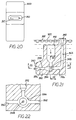
- FIGS 21 and 22 illustrate another version of the jet pump of Figure 19.
- a cast ceramic or refractory pump body 330 formed in accordance with the invention is disposed in molten metal 302.
- the pump body has a top molten metal inlet opening 332 which terminates at its lower end in a mixing chamber 334.
- a source of nitrogen gas is delivered through a gas passage inlet opening 342 down through a vertical passage 344 to a horizontal passage 346 which is axially aligned passage 336.
- Passage 346 terminates with a nozzle 348 which delivers the nitrogen gas such that it impinges upon the molten metal passing down into the mixing chamber, and then induces it to flow horizontally through the center of passage 336 toward the outlet opening.
- This embodiment illustrates how the molten metal inlet passage can be disposed at any suitable angle for recirculating the molten metal and/or while simultaneously degassing the molten metal. It further provides means for mixing cooler portions of the molten metal with hotter metal in order equalize the metal temperature.
- Figure 22 is an enlarged view of the mixing chamber and shows how the molten metal is introduced to mixing chamber 334 received from vertical passage 332 and a pair of horizontal passages 350 and 352. This embodiment illustrates how the molten metal can be introduced to the metal transfer conduit from any direction. It is independent of and does not require an inclined conduit.
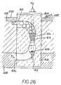
- Figure 26 illustrates another embodiment of the invention.
- a jet column reactor-lifting pump 400 is formed of a ceramic block 402 having a C-shaped molten metal-lifting passage 404.
- Passage 404 has a lower inlet opening 406 adjacent the bottom dross 408 illustrated in Figure 26 with the denser section lines.
- the metal-lifting passage has an upper outlet opening 410.
- both openings of the metal-lifting passage face the same direction as the outlet opening.
- Nitrogen is fed through a gas-receiving passage 412 into the molten metal-lifting passage to form high velocity jets that are centrally located for discharging the gas into a convergent/divergent nozzle 414 to generate a cascade of extremely small bubbles 416.
- Each bubble coalesces into larger bubbles as a function of the nozzle configuration. Since the inlet opening is disposed adjacent the bottom of the pot, the bottom dross will then mix with the nitrogen and become so emulsified that it floats towards the top of the bath to form a top dross 418, presented by the denser section lines in Figure 26.
- the top dross can then be skimmed or removed from the metal line 420 of the bath by a skimming device 422.
Landscapes
- Engineering & Computer Science (AREA)
- Chemical & Material Sciences (AREA)
- Mechanical Engineering (AREA)
- Chemical Kinetics & Catalysis (AREA)
- General Engineering & Computer Science (AREA)
- Materials Engineering (AREA)
- Metallurgy (AREA)
- Organic Chemistry (AREA)
- Manufacturing & Machinery (AREA)
- Manufacture And Refinement Of Metals (AREA)
- Vertical, Hearth, Or Arc Furnaces (AREA)
Applications Claiming Priority (2)
| Application Number | Priority Date | Filing Date | Title |
|---|---|---|---|
| US08/733,078 US5863314A (en) | 1995-06-12 | 1996-10-16 | Monolithic jet column reactor pump |
| US733078 | 1996-10-16 |
Publications (3)
| Publication Number | Publication Date |
|---|---|
| EP0845645A2 true EP0845645A2 (de) | 1998-06-03 |
| EP0845645A3 EP0845645A3 (de) | 1999-03-17 |
| EP0845645B1 EP0845645B1 (de) | 2003-01-02 |
Family
ID=24946133
Family Applications (1)
| Application Number | Title | Priority Date | Filing Date |
|---|---|---|---|
| EP97117955A Expired - Lifetime EP0845645B1 (de) | 1996-10-16 | 1997-10-16 | Einstückige Reaktor-Strahlpumpe mit vertikalen Strahl |
Country Status (4)
| Country | Link |
|---|---|
| US (1) | US5863314A (de) |
| EP (1) | EP0845645B1 (de) |
| CA (1) | CA2218944A1 (de) |
| DE (1) | DE69718133T2 (de) |
Cited By (5)
| Publication number | Priority date | Publication date | Assignee | Title |
|---|---|---|---|---|
| EP1426455A1 (de) * | 2002-12-04 | 2004-06-09 | Ing. Rauch Fertigungstechnik GmbH | Verfahren zum raschen Schmelzen eines Metalles, wie Magnesium, und Schmelzvorrichtung dazu |
| AU2009276301B2 (en) * | 2008-07-31 | 2015-06-18 | Commonwealth Scientific And Industrial Research Organisation | Production process |
| US9820001B2 (en) | 1998-11-10 | 2017-11-14 | Rovi Guides, Inc. | On-line schedule system with personalization features |
| EP4031308A4 (de) * | 2019-09-19 | 2022-10-19 | Burnstar Technologies (Pty) Ltd. | Ofen, fluidzuführbauteil, fluidreformierungssystem und verfahren zum reformieren eines fluids |
| AT527438A1 (de) * | 2023-07-25 | 2025-02-15 | Silmeta Silikate Fuer Die Metallurgische Ind Produktion Und Vertrieb Gesellschaft M B H & Co K G | Auffanggrube zur Aufnahme von Metallschmelze und Kühlwasser |
Families Citing this family (43)
| Publication number | Priority date | Publication date | Assignee | Title |
|---|---|---|---|---|
| US6039917A (en) * | 1995-06-12 | 2000-03-21 | Morando; Jorge A. | Jet column reactor pump with coaxial and/or lateral intake opening |
| US5984999A (en) * | 1998-04-10 | 1999-11-16 | Premelt Pump, Inc. | Apparatus having gas-actuated pump and charge well and method of melting metal therewith charge a well of a metal-melting furnace |
| US6354573B1 (en) * | 2000-09-25 | 2002-03-12 | Jorge A. Morando | Swimming pool high velocity heating system |
| US7402276B2 (en) | 2003-07-14 | 2008-07-22 | Cooper Paul V | Pump with rotating inlet |
| US20070253807A1 (en) | 2006-04-28 | 2007-11-01 | Cooper Paul V | Gas-transfer foot |
| US20050013715A1 (en) * | 2003-07-14 | 2005-01-20 | Cooper Paul V. | System for releasing gas into molten metal |
| US7470392B2 (en) * | 2003-07-14 | 2008-12-30 | Cooper Paul V | Molten metal pump components |
| US7906068B2 (en) | 2003-07-14 | 2011-03-15 | Cooper Paul V | Support post system for molten metal pump |
| WO2008128162A1 (en) * | 2007-04-12 | 2008-10-23 | Pyrotek, Inc. | Galvanizing bath apparatus |
| US9205490B2 (en) | 2007-06-21 | 2015-12-08 | Molten Metal Equipment Innovations, Llc | Transfer well system and method for making same |
| US9643247B2 (en) | 2007-06-21 | 2017-05-09 | Molten Metal Equipment Innovations, Llc | Molten metal transfer and degassing system |
| US8613884B2 (en) | 2007-06-21 | 2013-12-24 | Paul V. Cooper | Launder transfer insert and system |
| US9409232B2 (en) | 2007-06-21 | 2016-08-09 | Molten Metal Equipment Innovations, Llc | Molten metal transfer vessel and method of construction |
| US9410744B2 (en) | 2010-05-12 | 2016-08-09 | Molten Metal Equipment Innovations, Llc | Vessel transfer insert and system |
| US8337746B2 (en) | 2007-06-21 | 2012-12-25 | Cooper Paul V | Transferring molten metal from one structure to another |
| US8366993B2 (en) | 2007-06-21 | 2013-02-05 | Cooper Paul V | System and method for degassing molten metal |
| US9156087B2 (en) | 2007-06-21 | 2015-10-13 | Molten Metal Equipment Innovations, Llc | Molten metal transfer system and rotor |
| US8535603B2 (en) | 2009-08-07 | 2013-09-17 | Paul V. Cooper | Rotary degasser and rotor therefor |
| US8444911B2 (en) | 2009-08-07 | 2013-05-21 | Paul V. Cooper | Shaft and post tensioning device |
| US10428821B2 (en) * | 2009-08-07 | 2019-10-01 | Molten Metal Equipment Innovations, Llc | Quick submergence molten metal pump |
| US8524146B2 (en) | 2009-08-07 | 2013-09-03 | Paul V. Cooper | Rotary degassers and components therefor |
| US8449814B2 (en) * | 2009-08-07 | 2013-05-28 | Paul V. Cooper | Systems and methods for melting scrap metal |
| US8714914B2 (en) | 2009-09-08 | 2014-05-06 | Paul V. Cooper | Molten metal pump filter |
| US9108244B2 (en) * | 2009-09-09 | 2015-08-18 | Paul V. Cooper | Immersion heater for molten metal |
| UA115238C2 (uk) * | 2012-04-13 | 2017-10-10 | Арселорміттал Інвестігасьон І Десарролло Сл | Вдосконалений бульбашковий насос, стійкий до руйнуючої дії розплавленого алюмінію |
| US9903383B2 (en) | 2013-03-13 | 2018-02-27 | Molten Metal Equipment Innovations, Llc | Molten metal rotor with hardened top |
| US9011761B2 (en) | 2013-03-14 | 2015-04-21 | Paul V. Cooper | Ladle with transfer conduit |
| US10052688B2 (en) | 2013-03-15 | 2018-08-21 | Molten Metal Equipment Innovations, Llc | Transfer pump launder system |
| CN105829734B (zh) * | 2013-11-30 | 2018-06-12 | 安赛乐米塔尔公司 | 耐熔融铝腐蚀并且具有改进的流动曲线的改进的压气泵 |
| US9803922B2 (en) | 2014-05-09 | 2017-10-31 | Altek L.L.C. | System and method for melting light gauge scrap |
| US9686903B2 (en) * | 2014-06-17 | 2017-06-27 | Cnh Industrial Canada, Ltd. | Optimizing product flow in a drop chute by controlling the shape and position of vortices present in the system |
| US10465688B2 (en) | 2014-07-02 | 2019-11-05 | Molten Metal Equipment Innovations, Llc | Coupling and rotor shaft for molten metal devices |
| US10947980B2 (en) | 2015-02-02 | 2021-03-16 | Molten Metal Equipment Innovations, Llc | Molten metal rotor with hardened blade tips |
| WO2016187144A1 (en) * | 2015-05-15 | 2016-11-24 | Presswood Ronald G Jr | Method to recycle plastics, electronics, munitions or propellants using a metal reactant alloy composition |
| US10427192B2 (en) | 2015-05-15 | 2019-10-01 | Ronald G. Presswood, Jr. | Method to recycle plastics, electronics, munitions or propellants using a metal reactant alloy composition |
| US10267314B2 (en) | 2016-01-13 | 2019-04-23 | Molten Metal Equipment Innovations, Llc | Tensioned support shaft and other molten metal devices |
| US11149747B2 (en) | 2017-11-17 | 2021-10-19 | Molten Metal Equipment Innovations, Llc | Tensioned support post and other molten metal devices |
| US20200360990A1 (en) | 2019-05-17 | 2020-11-19 | Molten Metal Equipment Innovations, Llc | Molten Metal Transfer System and Method |
| FR3105796B1 (fr) * | 2019-12-26 | 2022-06-10 | Fives Stein | Dispositif pour l’evacuation de mattes de la surface d’un bain de metal liquide a l’interieur d’une descente de cloche d’une ligne de revetement en continu d’une bande metallique |
| CN112902663B (zh) * | 2021-04-11 | 2022-12-09 | 江西宏成铝业有限公司 | 浸没式熔炼系统 |
| US11873845B2 (en) | 2021-05-28 | 2024-01-16 | Molten Metal Equipment Innovations, Llc | Molten metal transfer device |
| US12146508B2 (en) | 2022-05-26 | 2024-11-19 | Molten Metal Equipment Innovations, Llc | Axial pump and riser |
| EP4561772A1 (de) | 2022-07-25 | 2025-06-04 | Cleveland-Cliffs Steel Properties Inc. | Verfahren zur gewinnung von krätze unter verwendung von erhitztem stickstoff und druckaufstauenden düsen |
Family Cites Families (6)
| Publication number | Priority date | Publication date | Assignee | Title |
|---|---|---|---|---|
| JPS5928834B2 (ja) * | 1979-05-15 | 1984-07-16 | ドルゼンコフ ボリス セルゲ−ビツチ | 溶融金属撹拌用ガスポンプ |
| JP2704675B2 (ja) * | 1990-12-28 | 1998-01-26 | 新日本製鐵株式会社 | 溶融亜鉛浴内の浴底堆積不純物除去装置 |
| US5203910A (en) * | 1991-11-27 | 1993-04-20 | Premelt Pump, Inc. | Molten metal conveying means and method of conveying molten metal from one place to another in a metal-melting furnace |
| US5360204A (en) * | 1993-09-20 | 1994-11-01 | Keibler-Thompson Corp. | Boom and lance for removing slag from crucible |
| JP2959409B2 (ja) * | 1994-09-07 | 1999-10-06 | 日本鋼管株式会社 | めっき浴のドロス除去装置 |
| US5683650A (en) * | 1995-06-12 | 1997-11-04 | Morando; Jorge A. | Bubble apparatus for removing and diluting dross in a steel treating bath |
-
1996
- 1996-10-16 US US08/733,078 patent/US5863314A/en not_active Expired - Lifetime
-
1997
- 1997-10-15 CA CA002218944A patent/CA2218944A1/en not_active Abandoned
- 1997-10-16 DE DE69718133T patent/DE69718133T2/de not_active Expired - Fee Related
- 1997-10-16 EP EP97117955A patent/EP0845645B1/de not_active Expired - Lifetime
Cited By (9)
| Publication number | Priority date | Publication date | Assignee | Title |
|---|---|---|---|---|
| US9820001B2 (en) | 1998-11-10 | 2017-11-14 | Rovi Guides, Inc. | On-line schedule system with personalization features |
| EP1426455A1 (de) * | 2002-12-04 | 2004-06-09 | Ing. Rauch Fertigungstechnik GmbH | Verfahren zum raschen Schmelzen eines Metalles, wie Magnesium, und Schmelzvorrichtung dazu |
| AU2009276301B2 (en) * | 2008-07-31 | 2015-06-18 | Commonwealth Scientific And Industrial Research Organisation | Production process |
| KR101606510B1 (ko) * | 2008-07-31 | 2016-03-25 | 커먼웰쓰 사이언티픽 앤드 인더스트리얼 리서치 오가니제이션 | 생산 방법 |
| EP4031308A4 (de) * | 2019-09-19 | 2022-10-19 | Burnstar Technologies (Pty) Ltd. | Ofen, fluidzuführbauteil, fluidreformierungssystem und verfahren zum reformieren eines fluids |
| US12359872B2 (en) | 2019-09-19 | 2025-07-15 | Burnstar Technologies (Pty) Ltd | Furnace, fluid feed component, fluid reforming system and method of reforming a fluid |
| AU2020350208B2 (en) * | 2019-09-19 | 2026-01-29 | Burnstar Technologies (Pty) Ltd | Furnace, fluid feed component, fluid reforming system and method of reforming a fluid |
| AT527438A1 (de) * | 2023-07-25 | 2025-02-15 | Silmeta Silikate Fuer Die Metallurgische Ind Produktion Und Vertrieb Gesellschaft M B H & Co K G | Auffanggrube zur Aufnahme von Metallschmelze und Kühlwasser |
| AT527438B1 (de) * | 2023-07-25 | 2025-08-15 | Silmeta Silikate Fuer Die Metallurgische Ind Produktion Und Vertrieb Gesellschaft M B H & Co K G | Auffanggrube zur Aufnahme von Metallschmelze und Kühlwasser |
Also Published As
| Publication number | Publication date |
|---|---|
| DE69718133D1 (de) | 2003-02-06 |
| EP0845645A3 (de) | 1999-03-17 |
| US5863314A (en) | 1999-01-26 |
| DE69718133T2 (de) | 2003-10-23 |
| CA2218944A1 (en) | 1998-04-16 |
| EP0845645B1 (de) | 2003-01-02 |
Similar Documents
| Publication | Publication Date | Title |
|---|---|---|
| EP0845645B1 (de) | Einstückige Reaktor-Strahlpumpe mit vertikalen Strahl | |
| US11759853B2 (en) | Melting metal on a raised surface | |
| US5660614A (en) | Gas treatment of molten metals | |
| US5650120A (en) | Bubble-operated recirculating pump for metal bath | |
| CA1305609C (en) | Treatment of molten light metals | |
| US9156087B2 (en) | Molten metal transfer system and rotor | |
| JP2015514954A (ja) | 溶融金属浸漬装置 | |
| US5340379A (en) | Jet flow device for injecting gas into molten metal and process | |
| US6056803A (en) | Injector for gas treatment of molten metals | |
| US20250060162A1 (en) | Metal melting apparatus, screen plate for metal melting, and method of melting metal | |
| US5020778A (en) | Apparatus for stirring molten metal | |
| EP0087409A1 (de) | Ofenanlage für glashütte | |
| US20230113438A1 (en) | Scrap submergence device and related processes | |
| JP6855084B1 (ja) | 金属溶解装置 | |
| JP6829491B1 (ja) | 金属溶解用スクリーン板及び金属溶解方法 | |
| US4014529A (en) | Device for vacuum-refining of molten metal | |
| JP6861442B1 (ja) | 金属溶解装置 | |
| CN101043960A (zh) | 熔化设备和方法 | |
| JP4220848B2 (ja) | 加熱機能を備えた鋼の連続鋳造用タンディッシュ | |
| JP4243711B2 (ja) | 坩堝炉 | |
| RU2100138C1 (ru) | Устройство для обработки металла в процессе непрерывной разливки | |
| CA1050757A (en) | Device for vacuum refining of molten metal | |
| SU155935A1 (de) |
Legal Events
| Date | Code | Title | Description |
|---|---|---|---|
| PUAI | Public reference made under article 153(3) epc to a published international application that has entered the european phase |
Free format text: ORIGINAL CODE: 0009012 |
|
| AK | Designated contracting states |
Kind code of ref document: A2 Designated state(s): DE FR GB IT |
|
| AX | Request for extension of the european patent |
Free format text: AL;LT;LV;RO;SI |
|
| PUAL | Search report despatched |
Free format text: ORIGINAL CODE: 0009013 |
|
| AK | Designated contracting states |
Kind code of ref document: A3 Designated state(s): AT BE CH DE DK ES FI FR GB GR IE IT LI LU MC NL PT SE |
|
| AX | Request for extension of the european patent |
Free format text: AL;LT;LV;RO;SI |
|
| 17P | Request for examination filed |
Effective date: 19990820 |
|
| AKX | Designation fees paid |
Free format text: DE FR GB IT |
|
| 17Q | First examination report despatched |
Effective date: 20000316 |
|
| GRAG | Despatch of communication of intention to grant |
Free format text: ORIGINAL CODE: EPIDOS AGRA |
|
| GRAG | Despatch of communication of intention to grant |
Free format text: ORIGINAL CODE: EPIDOS AGRA |
|
| GRAH | Despatch of communication of intention to grant a patent |
Free format text: ORIGINAL CODE: EPIDOS IGRA |
|
| GRAH | Despatch of communication of intention to grant a patent |
Free format text: ORIGINAL CODE: EPIDOS IGRA |
|
| GRAA | (expected) grant |
Free format text: ORIGINAL CODE: 0009210 |
|
| AK | Designated contracting states |
Kind code of ref document: B1 Designated state(s): DE FR GB IT |
|
| REG | Reference to a national code |
Ref country code: GB Ref legal event code: FG4D Free format text: 20030102 |
|
| REF | Corresponds to: |
Ref document number: 69718133 Country of ref document: DE Date of ref document: 20030206 Kind code of ref document: P |
|
| ET | Fr: translation filed | ||
| PG25 | Lapsed in a contracting state [announced via postgrant information from national office to epo] |
Ref country code: GB Free format text: LAPSE BECAUSE OF NON-PAYMENT OF DUE FEES Effective date: 20031016 |
|
| PGFP | Annual fee paid to national office [announced via postgrant information from national office to epo] |
Ref country code: FR Payment date: 20031021 Year of fee payment: 7 |
|
| PLBE | No opposition filed within time limit |
Free format text: ORIGINAL CODE: 0009261 |
|
| STAA | Information on the status of an ep patent application or granted ep patent |
Free format text: STATUS: NO OPPOSITION FILED WITHIN TIME LIMIT |
|
| 26N | No opposition filed |
Effective date: 20031003 |
|
| PG25 | Lapsed in a contracting state [announced via postgrant information from national office to epo] |
Ref country code: DE Free format text: LAPSE BECAUSE OF NON-PAYMENT OF DUE FEES Effective date: 20040501 |
|
| GBPC | Gb: european patent ceased through non-payment of renewal fee |
Effective date: 20031016 |
|
| PG25 | Lapsed in a contracting state [announced via postgrant information from national office to epo] |
Ref country code: FR Free format text: LAPSE BECAUSE OF NON-PAYMENT OF DUE FEES Effective date: 20050630 |
|
| REG | Reference to a national code |
Ref country code: FR Ref legal event code: ST |
|
| PG25 | Lapsed in a contracting state [announced via postgrant information from national office to epo] |
Ref country code: IT Free format text: LAPSE BECAUSE OF NON-PAYMENT OF DUE FEES Effective date: 20051016 |