EP0845834A2 - Méthode et appareil de réconfiguration des diagrammes d'antenne de rayonnement - Google Patents
Méthode et appareil de réconfiguration des diagrammes d'antenne de rayonnement Download PDFInfo
- Publication number
- EP0845834A2 EP0845834A2 EP97309499A EP97309499A EP0845834A2 EP 0845834 A2 EP0845834 A2 EP 0845834A2 EP 97309499 A EP97309499 A EP 97309499A EP 97309499 A EP97309499 A EP 97309499A EP 0845834 A2 EP0845834 A2 EP 0845834A2
- Authority
- EP
- European Patent Office
- Prior art keywords
- antenna
- feed
- contoured
- shape
- surface portions
- Prior art date
- Legal status (The legal status is an assumption and is not a legal conclusion. Google has not performed a legal analysis and makes no representation as to the accuracy of the status listed.)
- Withdrawn
Links
Images

Classifications
-
- H—ELECTRICITY
- H01—ELECTRIC ELEMENTS
- H01Q—ANTENNAS, i.e. RADIO AERIALS
- H01Q1/00—Details of, or arrangements associated with, antennas
- H01Q1/27—Adaptation for use in or on movable bodies
- H01Q1/28—Adaptation for use in or on aircraft, missiles, satellites, or balloons
- H01Q1/288—Satellite antennas
-
- H—ELECTRICITY
- H01—ELECTRIC ELEMENTS
- H01Q—ANTENNAS, i.e. RADIO AERIALS
- H01Q3/00—Arrangements for changing or varying the orientation or the shape of the directional pattern of the waves radiated from an antenna or antenna system
- H01Q3/12—Arrangements for changing or varying the orientation or the shape of the directional pattern of the waves radiated from an antenna or antenna system using mechanical relative movement between primary active elements and secondary devices of antennas or antenna systems
- H01Q3/16—Arrangements for changing or varying the orientation or the shape of the directional pattern of the waves radiated from an antenna or antenna system using mechanical relative movement between primary active elements and secondary devices of antennas or antenna systems for varying relative position of primary active element and a reflecting device
- H01Q3/20—Arrangements for changing or varying the orientation or the shape of the directional pattern of the waves radiated from an antenna or antenna system using mechanical relative movement between primary active elements and secondary devices of antennas or antenna systems for varying relative position of primary active element and a reflecting device wherein the primary active element is fixed and the reflecting device is movable
Definitions
- Antenna used for surveillance or communications satellites need to be shaped to provide a target pattern which conforms as closely as possible to the shape of the target location. This maximises the power directed at the target and increases the response of the associated system.
- multiple antenna radiation patterns must be generated.
- Prior art systems utilized a reflector antenna with a feed array which is connected to a power source through a variable power driver beam forming network. By proper excitation of the feed array, the antenna radiation pattern can be changed.
- the problem is in the beam forming network, which is a major source of passive intermodulation interference.
- the beam forming network also adds considerable weight and expanse to the system.
- an apparatus for reconfiguring an antenna system for radiating a contoured beam to multiple targets characterised in a single reflector antenna having reflective surface portions shaped to radiate at least two different contoured beams corresponding to different targets when each of said surface portions is independently excited by a source of energy, a single energy feed, designed to excite one of the antenna surface portions, fixed in a predetermined relation with said antenna and mounting means for the antenna which permits the antenna to move to at least two different positions relative to the energy feed, such that said reflective surface portions are independently excited, the positions corresponding respectively to at least two different targets.
- a method of reconfiguring an antenna to provide a contoured beam to multiple targets comprising the steps of:-
- the antenna is shaped to provide a predetermined contour and may be mounted for universal movement on its support.
- An electronically controlled drive mechanism can be operatively associated with the antenna to rotate the antenna to preselected positions corresponding to specific target locations.
- a fixed feed horn can be employed to excite the antenna to generate a first radiation pattern which conforms to the shape of a primary desired target location when the antenna is moved to a first position and a second radiation pattern which conforms to the shape of a secondary desired target location when the antenna is moved to a second position.
- Figure 1 is a schematic diagram of a multiple feed horn system of the prior art
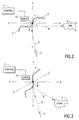
- Figure 2 is a schematic diagram of an apparatus constructed in accordance with the invention having a movable shaped antenna and shown in a first position with a single fixed feed horn used to form a contoured beam directed at the USA, and
- Figure 3 is a schematic diagram of the apparatus of Figure 2 showing the movable shaped antenna in a second position with the single fixed feed horn used to form a contoured beam directed at China.
- a prior art system consists of a shaped reflector antenna 1 and a radio frequency feed array 7.
- a beam forming network 9 powers the feed array 7 and switches the feed to reconfigure the reflected beam.
- the feed array directs radio frequency energy 5 and 5' at the reflector to form beams 6 and 6' contoured to the shape of the targets 4 or 4' to focus the energy in the desired location. By focusing the beam to the shape of the target, antenna gain is optimized. This type of system is unnecessarily complex and adds much weight and expense to the satellite.
- the reflecting surface of reflector antenna 1 is shaped having a node 8.
- the reflecting surface shape is designed using available optimizer computer techniques for analysing horn feed reflector antenna systems.
- the antenna 1 is mounted at 2 for universal movement about the orthogonal axes x-x, y-y, and z-z.
- the mounting means may be any suitable gimbal type mount that allows a complete flexibility of movement. In addition further movement may be provided by mounting the gimbal mount on a sliding track for translation along, for example the axis x-x.
- a drive mechanism 10 is provided to move the antenna between at least two positions in order to provide the multiple beams upon receiving signals from a control 11.
- Control 11 can be the on board computer, separate discrete logic, or a microprocessor depending on the complexity of the control required.
- the system of this invention is configured to radiate contoured patterns which conform to the location and shape of the USA and China when moved from a first position to a second position.
- Radiation feed horn 3 is placed at a fixed location, a predetermined distance from and angle to the antenna 1.
- the feed horn is designed to excite the antenna to radiate a contoured beam for each target.
- the antenna is moved from one position to another the feed energy excites a different portion of node 8.
- the antenna 1 is positioned by actuating the drive mechanism 10 through control 11 to a predetermined orientation relative to the feed horn 3.
- Radiation beam 5 excites the antenna 1 at one side of node 8 to reflect a contoured beam 6 conforming to the shape and location of a first target, for example the USA.
- a second target for example China will come into its range.
- Control 11 will activate the drive mechanism 10 to move the antenna to a second predetermined position relative to feed horn 3.
- Radiation beam 5 is emitted from feed horn 3 to excite the antenna 1 at a different point on node 8 and excite antenna 1 to reflect a second contoured beam 6' conforming to the shape and location of China.
- the contoured beams 6 and 6' are the result of the predetermined shape of the antenna 1 in conjunction with the fixed exciting energy of feed horn 3.
Landscapes
- Physics & Mathematics (AREA)
- Engineering & Computer Science (AREA)
- Astronomy & Astrophysics (AREA)
- General Physics & Mathematics (AREA)
- Remote Sensing (AREA)
- Aviation & Aerospace Engineering (AREA)
- Aerials With Secondary Devices (AREA)
- Variable-Direction Aerials And Aerial Arrays (AREA)
- Details Of Aerials (AREA)
Applications Claiming Priority (2)
| Application Number | Priority Date | Filing Date | Title |
|---|---|---|---|
| US08/758,968 US5945960A (en) | 1996-12-02 | 1996-12-02 | Method and apparatus for reconfiguring antenna radiation patterns |
| US758968 | 1996-12-02 |
Publications (2)
| Publication Number | Publication Date |
|---|---|
| EP0845834A2 true EP0845834A2 (fr) | 1998-06-03 |
| EP0845834A3 EP0845834A3 (fr) | 1999-10-06 |
Family
ID=25053851
Family Applications (1)
| Application Number | Title | Priority Date | Filing Date |
|---|---|---|---|
| EP97309499A Withdrawn EP0845834A3 (fr) | 1996-12-02 | 1997-11-25 | Méthode et appareil de réconfiguration des diagrammes d'antenne de rayonnement |
Country Status (3)
| Country | Link |
|---|---|
| US (1) | US5945960A (fr) |
| EP (1) | EP0845834A3 (fr) |
| JP (1) | JPH10247813A (fr) |
Cited By (3)
| Publication number | Priority date | Publication date | Assignee | Title |
|---|---|---|---|---|
| EP0915529A1 (fr) * | 1997-11-07 | 1999-05-12 | Space Systems/Loral, Inc. | Antenne de satellite positionable avec un faisceau reconfigurable |
| FR2888674A1 (fr) * | 2005-07-13 | 2007-01-19 | Alcatel Sa | Antenne reseau a reflecteur(s) conforme(s), a forte reconfigurabilite en orbite |
| EP3714510B1 (fr) | 2018-07-12 | 2021-04-21 | Airbus Defence and Space Limited | Antenne à réflecteur alimentée par réseau |
Families Citing this family (6)
| Publication number | Priority date | Publication date | Assignee | Title |
|---|---|---|---|---|
| US6326926B1 (en) | 2000-05-18 | 2001-12-04 | Telxon Corporation | Method of operating a wireless and a short-range wireless connection in the same frequency |
| US6633264B2 (en) * | 2000-12-21 | 2003-10-14 | Lockheed Martin Corporation | Earth coverage reflector antenna for geosynchronous spacecraft |
| US20050002742A1 (en) * | 2002-12-11 | 2005-01-06 | Martin Bachmann | Method and device for transporting powdery substances |
| US20070128389A1 (en) * | 2005-12-06 | 2007-06-07 | Dak Americas Llc | Process for manufacturing co-polyester barrier resins without solid-state polymerization, co-polyester resins made by the process, and clear mono-layer containers made of the co-polyester resins |
| US7358324B2 (en) | 2005-12-06 | 2008-04-15 | Dak Americas Llc | Manufacturing method of co-polyester resins for clear mono-layer containers with improved gas barrier characteristics |
| FR3026896B1 (fr) * | 2014-10-03 | 2018-07-06 | Thales | Antenne a reflecteur(s) conforme(s) reconfigurable en orbite |
Family Cites Families (12)
| Publication number | Priority date | Publication date | Assignee | Title |
|---|---|---|---|---|
| US4070678A (en) * | 1976-04-02 | 1978-01-24 | Raytheon Company | Wide angle scanning antenna assembly |
| DE3411838A1 (de) * | 1984-03-30 | 1985-10-10 | ANT Nachrichtentechnik GmbH, 7150 Backnang | Schwenkstrahlantenne fuer weltraumfunkstellen |
| US4647938A (en) * | 1984-10-29 | 1987-03-03 | Agence Spatiale Europeenne | Double grid reflector antenna |
| US4949092A (en) * | 1984-11-08 | 1990-08-14 | Highes Aircraft Company | Modularized contoured beam direct radiating antenna |
| DE3885308D1 (de) * | 1987-01-12 | 1993-12-09 | Nec Corp | Mehrstrahlantenne. |
| FR2648278A1 (fr) * | 1989-06-13 | 1990-12-14 | Europ Agence Spatiale | Antenne a faisceaux commutables |
| IT1240810B (it) * | 1990-03-28 | 1993-12-17 | Selenia Spazio Spa Ora Alenia | Sistema di puntamento fine per antenna a riflettore, particolarmente idoneo per applicazioni spaziali. |
| FR2674377B1 (fr) * | 1991-03-22 | 1993-06-04 | Alcatel Espace | Antenne radioelectrique a reflecteur multifocales. |
| FR2678111B1 (fr) * | 1991-06-19 | 1993-10-22 | Aerospatiale Ste Nationale Indle | Reflecteur d'antenne reconfigurable en service. |
| GB2264006B (en) * | 1992-02-01 | 1995-09-27 | British Aerospace Space And Co | A reflector antenna assembly for dual linear polarisation |
| US5528250A (en) * | 1992-11-18 | 1996-06-18 | Winegard Company | Deployable satellite antenna for use on vehicles |
| US5673057A (en) * | 1995-11-08 | 1997-09-30 | Trw Inc. | Three axis beam waveguide antenna |
-
1996
- 1996-12-02 US US08/758,968 patent/US5945960A/en not_active Expired - Lifetime
-
1997
- 1997-11-25 EP EP97309499A patent/EP0845834A3/fr not_active Withdrawn
- 1997-12-01 JP JP9329831A patent/JPH10247813A/ja active Pending
Cited By (6)
| Publication number | Priority date | Publication date | Assignee | Title |
|---|---|---|---|---|
| EP0915529A1 (fr) * | 1997-11-07 | 1999-05-12 | Space Systems/Loral, Inc. | Antenne de satellite positionable avec un faisceau reconfigurable |
| FR2888674A1 (fr) * | 2005-07-13 | 2007-01-19 | Alcatel Sa | Antenne reseau a reflecteur(s) conforme(s), a forte reconfigurabilite en orbite |
| WO2007007011A3 (fr) * | 2005-07-13 | 2007-07-19 | Alcatel Lucent | Antenne reseau a reflecteur(s) conforme(s), a forte reconfigurabilite en orbite |
| US7714792B2 (en) | 2005-07-13 | 2010-05-11 | Thales | Array antenna with shaped reflector(s), highly reconfigurable in orbit |
| EP3714510B1 (fr) | 2018-07-12 | 2021-04-21 | Airbus Defence and Space Limited | Antenne à réflecteur alimentée par réseau |
| US11831075B2 (en) | 2018-07-12 | 2023-11-28 | Airbus Defence And Space Limited | Array-fed reflector antenna |
Also Published As
| Publication number | Publication date |
|---|---|
| JPH10247813A (ja) | 1998-09-14 |
| EP0845834A3 (fr) | 1999-10-06 |
| US5945960A (en) | 1999-08-31 |
Similar Documents
| Publication | Publication Date | Title |
|---|---|---|
| JP3592914B2 (ja) | フィード装置/反射器のデフォーカスおよび反射器のジンバル動作による成形された反射器の軌道上における再構成方法および通信システム | |
| US5949370A (en) | Positionable satellite antenna with reconfigurable beam | |
| US6366256B1 (en) | Multi-beam reflector antenna system with a simple beamforming network | |
| WO1999060656A3 (fr) | Antenne de communication par satellite a faisceaux multiples | |
| JP7110532B2 (ja) | アレイ給電反射鏡アンテナ | |
| US6392611B1 (en) | Array fed multiple beam array reflector antenna systems and method | |
| JP2000515242A (ja) | 車両に使用されるレーダセンサ | |
| US5945960A (en) | Method and apparatus for reconfiguring antenna radiation patterns | |
| JPH06318817A (ja) | 複数のビ−ムカバー範囲を生成するための成形二重反射器アンテナシステム | |
| RU2708908C2 (ru) | Система, устройство и способ для настройки удаленной антенны | |
| JPH11225018A (ja) | 多重ビーム用成形リフレクタ・アンテナ | |
| US5321413A (en) | Offset active antenna having two reflectors | |
| US4631547A (en) | Reflector antenna having sidelobe suppression elements | |
| EP1207584B1 (fr) | Antenne à réflecteur intégrée à deux faisceaux | |
| EP0139482A2 (fr) | Antenne double réflecteur à balayage | |
| JP2649191B2 (ja) | 車載レーダ用リフレクタ付アンテナ | |
| JP2882183B2 (ja) | アンテナ装置 | |
| JP6818787B2 (ja) | アンテナ装置、通信衛星、及びアンテナ装置搭載方法 | |
| JPS6017163B2 (ja) | 複ビーム走査アンテナ | |
| JP2705612B2 (ja) | ビーム給電型複反射鏡アンテナ | |
| JP3034262B2 (ja) | 開口面アンテナ装置 | |
| JPH0232604A (ja) | マルチビームアンテナ | |
| JPH0733454Y2 (ja) | アンテナ装置 | |
| RU97115091A (ru) | Способ и устройство формирования управляемой по ширине диаграммы направленности антенны рлс | |
| JPH066591Y2 (ja) | アンテナ装置 |
Legal Events
| Date | Code | Title | Description |
|---|---|---|---|
| PUAI | Public reference made under article 153(3) epc to a published international application that has entered the european phase |
Free format text: ORIGINAL CODE: 0009012 |
|
| AK | Designated contracting states |
Kind code of ref document: A2 Designated state(s): DE FR GB IT |
|
| AX | Request for extension of the european patent |
Free format text: AL;LT;LV;MK;RO;SI |
|
| PUAL | Search report despatched |
Free format text: ORIGINAL CODE: 0009013 |
|
| AK | Designated contracting states |
Kind code of ref document: A3 Designated state(s): AT BE CH DE DK ES FI FR GB GR IE IT LI LU MC NL PT SE |
|
| AX | Request for extension of the european patent |
Free format text: AL;LT;LV;MK;RO;SI |
|
| 17P | Request for examination filed |
Effective date: 19991124 |
|
| AKX | Designation fees paid |
Free format text: DE FR GB IT |
|
| 17Q | First examination report despatched |
Effective date: 20030416 |
|
| STAA | Information on the status of an ep patent application or granted ep patent |
Free format text: STATUS: THE APPLICATION HAS BEEN WITHDRAWN |
|
| 18W | Application withdrawn |
Effective date: 20030710 |