EP0846362B1 - Systeme d'alimentation electrique pour appareil pourvu de batteries rechargeable - Google Patents
Systeme d'alimentation electrique pour appareil pourvu de batteries rechargeable Download PDFInfo
- Publication number
- EP0846362B1 EP0846362B1 EP97920920A EP97920920A EP0846362B1 EP 0846362 B1 EP0846362 B1 EP 0846362B1 EP 97920920 A EP97920920 A EP 97920920A EP 97920920 A EP97920920 A EP 97920920A EP 0846362 B1 EP0846362 B1 EP 0846362B1
- Authority
- EP
- European Patent Office
- Prior art keywords
- power supply
- svr
- battery
- current
- supply unit
- Prior art date
- Legal status (The legal status is an assumption and is not a legal conclusion. Google has not performed a legal analysis and makes no representation as to the accuracy of the status listed.)
- Expired - Lifetime
Links
Images




Classifications
-
- H—ELECTRICITY
- H02—GENERATION; CONVERSION OR DISTRIBUTION OF ELECTRIC POWER
- H02J—ELECTRIC POWER NETWORKS; CIRCUIT ARRANGEMENTS OR SYSTEMS FOR SUPPLYING OR DISTRIBUTING ELECTRIC POWER; SYSTEMS FOR STORING ELECTRIC ENERGY
- H02J7/00—Circuit arrangements for charging or discharging batteries or for supplying loads from batteries
- H02J7/40—Circuit arrangements for charging or discharging batteries or for supplying loads from batteries characterised by the exchange of charge or discharge related data
- H02J7/44—Circuit arrangements for charging or discharging batteries or for supplying loads from batteries characterised by the exchange of charge or discharge related data between battery management systems and power sources
-
- H—ELECTRICITY
- H02—GENERATION; CONVERSION OR DISTRIBUTION OF ELECTRIC POWER
- H02J—ELECTRIC POWER NETWORKS; CIRCUIT ARRANGEMENTS OR SYSTEMS FOR SUPPLYING OR DISTRIBUTING ELECTRIC POWER; SYSTEMS FOR STORING ELECTRIC ENERGY
- H02J7/00—Circuit arrangements for charging or discharging batteries or for supplying loads from batteries
- H02J7/485—Circuit arrangements for charging or discharging batteries or for supplying loads from batteries with provisions for charging different types of batteries
-
- H—ELECTRICITY
- H02—GENERATION; CONVERSION OR DISTRIBUTION OF ELECTRIC POWER
- H02J—ELECTRIC POWER NETWORKS; CIRCUIT ARRANGEMENTS OR SYSTEMS FOR SUPPLYING OR DISTRIBUTING ELECTRIC POWER; SYSTEMS FOR STORING ELECTRIC ENERGY
- H02J7/00—Circuit arrangements for charging or discharging batteries or for supplying loads from batteries
- H02J7/865—Battery or charger load switching, e.g. concurrent charging and load supply
-
- Y—GENERAL TAGGING OF NEW TECHNOLOGICAL DEVELOPMENTS; GENERAL TAGGING OF CROSS-SECTIONAL TECHNOLOGIES SPANNING OVER SEVERAL SECTIONS OF THE IPC; TECHNICAL SUBJECTS COVERED BY FORMER USPC CROSS-REFERENCE ART COLLECTIONS [XRACs] AND DIGESTS
- Y02—TECHNOLOGIES OR APPLICATIONS FOR MITIGATION OR ADAPTATION AGAINST CLIMATE CHANGE
- Y02E—REDUCTION OF GREENHOUSE GAS [GHG] EMISSIONS, RELATED TO ENERGY GENERATION, TRANSMISSION OR DISTRIBUTION
- Y02E60/00—Enabling technologies; Technologies with a potential or indirect contribution to GHG emissions mitigation
- Y02E60/10—Energy storage using batteries
Definitions
- the invention relates to a power supply system comprising: an apparatus with a rechargeable battery, and a power supply unit which can be coupled to the apparatus to supply current to the apparatus, the power supply unit comprising means for stopping the power supply unit during breaks in which no current is supplied to the apparatus; the apparatus comprising means for transmitting a status signal to the power supply unit during the breaks; and the power supply unit comprising means for detecting the status signal during the breaks and means for changing the current intensity of the current in response to the status signal.
- United States Patent No. 4,775,827 discloses a power supply system in which the power supply unit comprises a DC-DC converter, which converts the rectified mains voltage into a low direct voltage with which the battery of the apparatus is charged.
- the power supply unit being constructed as an adapter which can be plugged into the wall outlet of the mains and the rechargeable apparatus being coupled to the adapter by a cord.
- the power supply unit can rapidly charge the battery of the apparatus. However, this involves the risk that the battery is overloaded and becomes defective.
- the apparatus should be capable in some way or another of communicating to the power supply unit that the battery is full and that charging should be stopped and should be continued with a safe small charging current, also referred to as trickle charging current.
- This communication capability requires a communication channel between the apparatus and the power supply unit. This communication channel requires additional wires in the connecting cord.
- an embodiment of the power supply system in accordance with the invention is characterized in that the apparatus comprises an electronic switch for short-circuiting the rectifier diode during the breaks in order to generate a pulse by way of status signal.
- the switched-mode power supply in the power supply unit is idle.
- the rectifier diode in the secondary circuit is short-circuited by the electronic switch, the battery voltage is applied to the secondary winding.
- the transformer transmits the voltage pulse to the primary winding or to an auxiliary winding, where it is detected by the means for detection in the power supply unit.
- the communication between the apparatus and the power supply unit is thus brought about by transmitting or not transmitting a pulse to the power supply unit during the breaks.
- the power supply unit switches the current intensity of the average current to another value. If no pulse is received during a break the power supply unit continues to supply the same current. By switching between two current intensities it is possible to obtain an average current for charging the battery.
- an embodiment of the power supply system comprises means for measuring a charging condition of the battery and means for activating the electronic switch when a predetermined value of the charging condition is reached.
- the means for measuring the charging condition can be implemented as a simple battery voltage measurement device or as a complex battery management system as known, inter alia, from the afore-mentioned United States Patent No. 4,775,827.
- the electronic switch is activated in each break and a pulse is transmitted to the power supply unit, which is thus always forced to supply the comparatively small current to the battery after each break.
- the comparatively small current is preferably adequate for trickle-charging of the battery, whereas the comparatively large current is preferably adequate for rapid charging of the battery.
- Charging of the battery B should be stopped when the battery B is full, in order to preclude overcharging. Moreover, the magnitude of the charging current should be controlled somehow or other during charging. Since the power supply unit PSU and the battery B are physically separated from one another by a two-wire cord the same two wires should in some way or another allow communication from the shaver SVR to the power supply unit PSU to provide information about the degree of charging of the battery B and the magnitude of the charging current. According to the invention, a communication protocol has been provided, the communication from the shaver SVR to the power supply unit PSU being time-multiplexed with the supply of charging current from the power supply unit PSU to the shaver SVR.
- the shaver SVR further comprises means for detecting the breaks in the current supply and means for transmitting a status signal to the power supply unit PSU during the breaks.
- the power supply unit PSU further comprises means for detecting the status signal during the breaks and means for changing the current intensity of the charging current in response to the status signal.
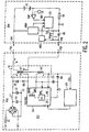
- the power supply unit PSU in Figure 2 comprises a mains voltage rectifier D1 and a smoothing filter C1, L1, C2.
- the flyback converter converts a direct voltage appearing across the capacitor C2 into a low direct voltage for charging the battery B in the shaver SVR.
- the flyback converter comprises a transformer TR having a primary winding Lp connected across the direct voltage on the capacitor C2 via a switching transistor.
- the switching transistor forms part of a switched-mode power supply (SMPS) integrated circuit (IC) ICA of the type TEA 1400 from Philips Electronics.
- SMPS switched-mode power supply
- the flyback converter When the signal EN is high, the flyback converter is operative and the battery is charged with a current whose average value is determined by the design of the flyback converter.
- An enable signal EN having a comparatively high duty cycle i.e. a signal which is comparatively often high, gives rise to a charging current of comparatively large average value, by means of which the battery can be charged rapidly (fast charge).
- An enable signal EN having a comparatively small duty cycle i.e. a signal which is comparatively often low, gives rise to a charging current having a comparatively small average value, by means of which the battery can be charged slowly (trickle charge).
- the operation of a flyback converter is assumed to be known and for more details about the operation of the SMPS-IC TEA 1400 reference is made to the relevant documentation of Philips Electronics.
- the control unit CTL By means of a status signal STS the control unit CTL temporarily turns on a switching transistor T if the average value of the charging current Is is too large or if the battery B is full.
- this short-circuit is allowed only during the breaks in the charging current Is.
- the no-current detector NCD has been provided, which monitors the voltage on the terminal SVB and which indicates to the control unit CTL when the flyback converter is idle.
- the voltage on the terminal SVN pulsates when the flyback converter is operative and is constant when the flyback converter is idle.
- the temporary short-circuit of the diode D5 results in the battery voltage appearing temporarily across the first secondary winding Ls1.
- the voltage pulse on the first secondary winding Ls1 as a result of the short-circuit of the diode D5 is transferred to the second secondary winding, where it can be detected by means of the status detector STD.
- an enable signal EN of the SLW type is selected in the next interval.
- the comparatively short time during which the enable signal EN is high can accommodate only a few oscillation periods of the flyback converter.
- the waveform diagram V shows one oscillation period but a larger number is also possible.
- the average charging current during this interval is much smaller. If in each break a voltage pulse STS would be detected, this small average charging current would be supplied in each subsequent interval.
- the average value of the charging current measured over a plurality of intervals t 1 and breaks t 0 , can be adapted in such a manner that the battery B is charged with a trickle charging current of, for example, 25 mA.
- the signals FST and SLW are generated by means of inverters of a hex Schmitt trigger CD40106.
- the first inverter with the resistor R5 and the capacitor C5 operates as a clock oscillator, whose output voltage is buffered by the second inverter.
- the duty cycle of the clock signal is 50%.
- the falling edges of the clock signal are differentiated by means of a capacitor C6 and a resistor R6 and are applied to a third inverter to derive the signal SLW with a duty cycle of approximately 2%.
- the falling edges of the signal SLW are once more differentiated by means of a capacitor C7 and a resistor R7 and are applied to a fourth inverter to derive a signal which is high for 100 ⁇ s.
- a second input of the AND gate receives an inverted FST signal, whose falling edge is delayed by means of a resistor R8, a diode D6 and a capacitor C9 in order to suppress undesirable effects of any additional oscillation cycles which may occur after the enable signal EN has become zero.
- the capacitor C9 When the signal FST goes low, i.e. at the beginning of a break, the capacitor C9 will discharge comparatively slowly via the resistor R8. At the end of the break the signal FST goes high and the capacitor C9 will be charged comparatively rapidly via the diode D6.
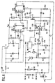
- the average charging current is monitored by means of an integrating amplifier U2A and a comparator U2B, both of the type TLC252.
- the voltage across the current measuring resistor R5 is filtered by means of a low-pass filter R6/C6 and is amplified by the amplifierU2A, the gain factor being adjustable by means of a feedback resistor R14 to a value adapted to the type of battery.
- the comparator U2B compares the output voltage of the amplifier U2A with a reference voltage generated by a zener diode D5, which receives a bias current from the voltage supply Vdd via a resistor R9. The output of the comparator is high if the applied voltage is higher than the reference voltage.
- the output Q of the one-shot U 1B drives the gate of the transistor T2 by means of which the diode D4 is temporarily short-circuited during the breaks if a voltage pulse is to be applied to the power supply unit.
- the duration of the voltage pulse is determined by a resistor R3 and a capacitor C4 connected to the terminals RC and CX of the one-shot U1B.
- a voltage pulse is generated only if the reset input R of the one-shot U1B is high, i.e. if the average current is too large or if the battery is full.
- Figure 7 shows the shaver SVR of Figure 1 with the motor M which drives the shaving heads SH.
- the motor M is started with the switch SW, which connects the motor M to the rechargeable battery B, which together with the other electronic components, for example those of the circuit shown in Figure 6, is accommodated on a printed circuit board PCB in the shaver SVR.
- Figure 7 further shows the power supply unit PSU of Figure 2, which has an integrated mains plug PLG and the two-wire connecting cord CRD, which can be coupled to an inlet (not shown) of the shaver SVR by means of an outlet OTL.
Landscapes
- Engineering & Computer Science (AREA)
- Power Engineering (AREA)
- Charge And Discharge Circuits For Batteries Or The Like (AREA)
- Dc-Dc Converters (AREA)
- Stand-By Power Supply Arrangements (AREA)
Claims (8)
- Système d'alimentation de puissance comprenant: un appareil (SVR) muni d'une batterie rechargeable (B), et une unité d'alimentation de puissance (PSU) qui peut être couplée à l'appareil (SVR) pour fournir du courant d'alimentation à l'appareil (SVR), l'unité d'alimentation de puissance (PSU) comprenant des moyens (ICA, EN) pour arrêter l'unité d'alimentation de puissance (PSU) pendant des pauses pendant lesquelles aucun courant n'est fourni à l'appareil (SVR); l'appareil (SVR) comprenant des moyens (T, CTL) permettant de transmettre un signal d'état (STS) à l'unité d'alimentation de puissance (PSU) pendant les pauses; et l'unité d'alimentation de puissance (PSU) comprenant des moyens (STD) servant à détecter le signal d'état (STS) pendant les pauses et des moyens (ICA) pour changer l'intensité de courant en réponse au signal d'état, caractérisé en ce que l'unité d'alimentation de puissance (PSU) comprend une alimentation de puissance en mode de commutation (DCC) qui est arrêtée pendant les pauses, et en ce que l'appareil (SVR) est muni de moyens (NCD) servant à détecter les pauses dans l'alimentation de courant.
- Système d'alimentation de puissance selon la revendication 1, caractérisé en ce que l'alimentation de puissance en mode de commutation comprend un convertisseur de récupération (ICA) présentant un transformateur (TR), dont un enroulement secondaire (Ls1) peut être couplé à au moins la batterie rechargeable (B) par l'intermédiaire d'une diode redresseuse (D 5).
- Système d'alimentation de puissance selon la revendication 2, caractérisé en ce que l'appareil (SVR) comprend un commutateur électronique (T) permettant de court-circuiter la diode redresseuse (D 5) pendant les pauses afin d'engendrer une impulsion à titre de signal d'état.
- Système d'alimentation de puissance selon la revendication 3, caractérisé en ce que le convertisseur de récupération est conçu pour fournir un courant relativement faible (SLW) après la détection de l'impulsion et pour fournir un courant relativement intense (FST) en l'absence de l'impulsion.
- Système d'alimentation de puissance selon la revendication 4, caractérisé en ce que l'appareil (SVR) est muni de moyens (CMP, REF) pour la mesure d'un courant moyen circulant à la batterie (B) et de moyens (CTL) pour activer le commutateur électronique (T) lorsque la valeur moyenne dépasse une valeur de seuil.
- Système d'alimentation de puissance selon la revendication 4 ou 5, caractérisé en ce que l'appareil (SVR) est muni de moyens (BMU) pour la mesure d'une condition de charge de la batterie (B) et de moyens (CTL) pour activer le commutateur électronique (T) lorsqu'une valeur préalablement déterminée de la condition de charge est atteinte.
- Système d'alimentation de puissance selon la revendication 4, 5 ou 6, caractérisé en ce que le courant relativement faible est approprié à la charge d'entretien de la batterie (B).
- Rasoir électrique (SVR) comprenant: une batterie rechargeable (B), un moteur électrique (M), un commutateur (SW) servant à connecter le moteur (M) à la batterie (B), et un système d'alimentation de puissance comme revendiqué dans l'une des revendications précédentes pour la charge de la batterie (B) et/ou l'alimentation d'au moins le moteur (M).
Priority Applications (1)
| Application Number | Priority Date | Filing Date | Title |
|---|---|---|---|
| EP97920920A EP0846362B1 (fr) | 1996-06-21 | 1997-05-28 | Systeme d'alimentation electrique pour appareil pourvu de batteries rechargeable |
Applications Claiming Priority (4)
| Application Number | Priority Date | Filing Date | Title |
|---|---|---|---|
| EP96201734 | 1996-06-21 | ||
| EP96201734 | 1996-06-21 | ||
| EP97920920A EP0846362B1 (fr) | 1996-06-21 | 1997-05-28 | Systeme d'alimentation electrique pour appareil pourvu de batteries rechargeable |
| PCT/IB1997/000609 WO1997049159A2 (fr) | 1996-06-21 | 1997-05-28 | Systeme d'alimentation electrique pour appareil pourvu de batteries rechargeables et unite d'alimentation et appareillage concernant un tel systeme |
Publications (2)
| Publication Number | Publication Date |
|---|---|
| EP0846362A2 EP0846362A2 (fr) | 1998-06-10 |
| EP0846362B1 true EP0846362B1 (fr) | 2003-09-17 |
Family
ID=8224101
Family Applications (1)
| Application Number | Title | Priority Date | Filing Date |
|---|---|---|---|
| EP97920920A Expired - Lifetime EP0846362B1 (fr) | 1996-06-21 | 1997-05-28 | Systeme d'alimentation electrique pour appareil pourvu de batteries rechargeable |
Country Status (7)
| Country | Link |
|---|---|
| US (1) | US5859524A (fr) |
| EP (1) | EP0846362B1 (fr) |
| JP (1) | JP3836152B2 (fr) |
| CN (1) | CN1104074C (fr) |
| AT (1) | ATE250292T1 (fr) |
| DE (1) | DE69724917T2 (fr) |
| WO (1) | WO1997049159A2 (fr) |
Cited By (3)
| Publication number | Priority date | Publication date | Assignee | Title |
|---|---|---|---|---|
| US8154248B2 (en) | 2008-10-07 | 2012-04-10 | Black & Decker Inc. | Signal for pre-charge selection in lithium charging and discharge control/pre-charge function |
| US8269458B2 (en) | 2008-10-07 | 2012-09-18 | Black & Decker Inc. | Shared control of thermistor and dual purpose thermistor line |
| US9124118B2 (en) | 2011-09-16 | 2015-09-01 | Braun Gmbh | Circuit for a small electric appliance with an accumulator and method for measuring a charging current |
Families Citing this family (37)
| Publication number | Priority date | Publication date | Assignee | Title |
|---|---|---|---|---|
| US20040072889A1 (en) * | 1997-04-21 | 2004-04-15 | Pharmacia Corporation | Method of using a COX-2 inhibitor and an alkylating-type antineoplastic agent as a combination therapy in the treatment of neoplasia |
| DE19754964A1 (de) * | 1997-12-11 | 1999-06-17 | Bayerische Motoren Werke Ag | Vorrichtung zur Energieversorgung eines Kraftfahrzeuges |
| JP2001519999A (ja) * | 1998-02-03 | 2001-10-23 | コーニンクレッカ フィリップス エレクトロニクス エヌ ヴィ | 同期整流による切換電圧変換器 |
| JP3882319B2 (ja) * | 1998-03-10 | 2007-02-14 | ソニー株式会社 | 電源供給アダプタ、電子機器および信号伝送システム |
| US6172480B1 (en) | 1998-10-23 | 2001-01-09 | Primetech Electronics, Inc. | Compact fast battery charger |
| ES2155765B1 (es) * | 1998-12-23 | 2001-12-01 | Montajes Y Proyectos Electrote | Cargador de baterias. |
| CN1269283C (zh) * | 2000-08-31 | 2006-08-09 | 皇家菲利浦电子有限公司 | 包括用于显示充电状态的装置的可充电设备 |
| EP1446864A2 (fr) | 2001-09-26 | 2004-08-18 | Koninklijke Philips Electronics N.V. | Architecture d'alimentation electrique a topologie divisee |
| DE10203512B4 (de) | 2002-01-30 | 2021-09-02 | Robert Bosch Gmbh | Handwerkzeugmaschine mit einem elektrischen Antrieb, einem Schaltmittel und einer Batterieeinheit |
| FR2842360A1 (fr) * | 2002-07-12 | 2004-01-16 | Hawker Sa | Procede et systeme de communication entre un dispositif de controle et de gestion d'une batterie et un chargeur de batterie |
| CN2829178Y (zh) * | 2004-04-21 | 2006-10-18 | 美国凹凸微系有限公司 | 对容性负载充电的电容充电电路 |
| US7486967B2 (en) * | 2005-04-13 | 2009-02-03 | Lemko Corporation | System, method, and device for providing communications using a distributed mobile architecture |
| US7501794B2 (en) * | 2004-12-17 | 2009-03-10 | Sigmatel, Inc. | System, method and semiconductor device for charging a secondary battery |
| GB2444659B (en) * | 2004-12-17 | 2008-09-03 | Sigmatel Inc | System, method and semiconductor device for charging a secondary battery |
| US7489105B2 (en) | 2005-03-21 | 2009-02-10 | Eveready Battery Company, Inc. | Portable power supply |
| US20060290326A1 (en) * | 2005-06-24 | 2006-12-28 | Microsoft Corporation | Protocols for reporting power status over multiple buses |
| US7531986B2 (en) * | 2006-02-23 | 2009-05-12 | Eveready Battery Company, Inc. | Power supply for battery powered devices |
| CN101589557B (zh) | 2007-01-25 | 2014-05-07 | 永备电池有限公司 | 应用扩展器设备 |
| KR101113415B1 (ko) | 2009-12-29 | 2012-03-02 | 삼성에스디아이 주식회사 | 배터리 팩의 보호 회로 |
| TWI486753B (zh) * | 2010-01-12 | 2015-06-01 | 緯創資通股份有限公司 | 電源供應系統及可攜式電子裝置 |
| KR101192010B1 (ko) * | 2011-02-10 | 2012-10-16 | 삼성에스디아이 주식회사 | 배터리의 충전 제어 시스템 및 그를 포함하는 배터리 팩 |
| US8941363B2 (en) * | 2011-05-27 | 2015-01-27 | Empire Technology Development Llc | Device battery management |
| WO2013026037A2 (fr) * | 2011-08-17 | 2013-02-21 | Bias Power, Inc. | Alimentation électrique régulée en courant à commande de tension dynamique |
| TWI456864B (zh) * | 2012-03-09 | 2014-10-11 | Acer Inc | 充電電源偵測切換裝置 |
| EP2717449B1 (fr) | 2012-10-05 | 2016-12-14 | Nxp B.V. | Alimentation électrique à découpage isolée |
| EP2717450B1 (fr) | 2012-10-05 | 2016-12-28 | Nxp B.V. | Alimentation à découpage isolée |
| US9531264B2 (en) * | 2013-02-20 | 2016-12-27 | Power Integrations, Inc. | Auxiliary recharge |
| US9735663B2 (en) | 2013-02-20 | 2017-08-15 | Power Integrations, Inc. | BJT drive scheme |
| RU2543507C1 (ru) * | 2013-08-27 | 2015-03-10 | Федеральное государственное бюджетное учреждение науки Институт проблем морских технологий Дальневосточного отделения Российской академии наук (ИПМТ ДВО РАН) | Устройство для зарядки аккумуляторной батареи подводного объекта |
| US10514743B2 (en) * | 2013-10-29 | 2019-12-24 | Velvetwire Llc | Software controlled power supply |
| RU2689304C2 (ru) * | 2014-01-13 | 2019-05-27 | Филипс Лайтинг Холдинг Б.В. | Буферизующий конденсатор для выпрямителя с диодным мостом с управляемым током разрядки |
| WO2017020930A1 (fr) * | 2015-07-31 | 2017-02-09 | Huawei Technologies Co., Ltd. | Dispositif de communication sans fil et procédé de récupération d'énergie rf |
| RU2611068C1 (ru) * | 2015-12-30 | 2017-02-21 | Федеральное государственное бюджетное учреждение науки Институт проблем морских технологий Дальневосточного отделения Российской академии наук (ИПМТ ДВО РАН) | Устройство для зарядки аккумуляторной батареи автономного необитаемого подводного объекта |
| US9847725B2 (en) * | 2016-04-25 | 2017-12-19 | Aktiebolaget Skf | Relay drive with voltage isolation |
| RU2648231C1 (ru) * | 2017-04-26 | 2018-03-23 | Федеральное государственное бюджетное учреждение науки Институт проблем морских технологий Дальневосточного отделения Российской академии наук (ИПМТ ДВО РАН) | Устройство для бесконтактной передачи электроэнергии на подводный аппарат |
| RU2669198C1 (ru) * | 2017-12-18 | 2018-10-09 | Федеральное государственное бюджетное учреждение науки Институт проблем морских технологий Дальневосточного отделения Российской академии наук (ИПМТ ДВО РАН) | Устройство для зарядки аккумуляторной батареи автономного необитаемого подводного аппарата |
| RU2750396C1 (ru) * | 2020-12-28 | 2021-06-28 | Федеральное государственное автономное образовательное учреждение высшего образования "Санкт-Петербургский государственный университет аэрокосмического приборостроения" | Система энергообеспечения подводного аппарата |
Family Cites Families (7)
| Publication number | Priority date | Publication date | Assignee | Title |
|---|---|---|---|---|
| DE3528659A1 (de) * | 1985-08-09 | 1987-02-19 | Jungheinrich Kg | Batterieladeanlage |
| NL8601243A (nl) * | 1986-05-15 | 1987-12-01 | Philips Nv | Inrichting voor het weergeven van de ladingstoestand van een batterij. |
| US4910654A (en) * | 1989-01-10 | 1990-03-20 | Uniphase Corporation | Current limiting scheme for the AC input circuit to a switch mode power supply |
| GB2242793B (en) * | 1990-04-05 | 1994-08-10 | Technophone Ltd | Battery charging apparatus |
| US5206097A (en) * | 1991-06-05 | 1993-04-27 | Motorola, Inc. | Battery package having a communication window |
| DE4219999A1 (de) * | 1992-06-19 | 1993-12-23 | Bosch Gmbh Robert | Ladeeinrichtung |
| JPH08329992A (ja) * | 1995-05-29 | 1996-12-13 | Saitama Nippon Denki Kk | 電池パックと充電器 |
-
1997
- 1997-05-28 DE DE69724917T patent/DE69724917T2/de not_active Expired - Fee Related
- 1997-05-28 EP EP97920920A patent/EP0846362B1/fr not_active Expired - Lifetime
- 1997-05-28 AT AT97920920T patent/ATE250292T1/de not_active IP Right Cessation
- 1997-05-28 CN CN97191066A patent/CN1104074C/zh not_active Expired - Fee Related
- 1997-05-28 WO PCT/IB1997/000609 patent/WO1997049159A2/fr not_active Ceased
- 1997-05-28 JP JP50257998A patent/JP3836152B2/ja not_active Expired - Fee Related
- 1997-06-17 US US08/877,378 patent/US5859524A/en not_active Expired - Fee Related
Cited By (3)
| Publication number | Priority date | Publication date | Assignee | Title |
|---|---|---|---|---|
| US8154248B2 (en) | 2008-10-07 | 2012-04-10 | Black & Decker Inc. | Signal for pre-charge selection in lithium charging and discharge control/pre-charge function |
| US8269458B2 (en) | 2008-10-07 | 2012-09-18 | Black & Decker Inc. | Shared control of thermistor and dual purpose thermistor line |
| US9124118B2 (en) | 2011-09-16 | 2015-09-01 | Braun Gmbh | Circuit for a small electric appliance with an accumulator and method for measuring a charging current |
Also Published As
| Publication number | Publication date |
|---|---|
| JP3836152B2 (ja) | 2006-10-18 |
| US5859524A (en) | 1999-01-12 |
| JPH11511958A (ja) | 1999-10-12 |
| WO1997049159A3 (fr) | 1998-02-12 |
| DE69724917T2 (de) | 2004-07-22 |
| DE69724917D1 (de) | 2003-10-23 |
| WO1997049159A2 (fr) | 1997-12-24 |
| CN1104074C (zh) | 2003-03-26 |
| CN1198850A (zh) | 1998-11-11 |
| EP0846362A2 (fr) | 1998-06-10 |
| ATE250292T1 (de) | 2003-10-15 |
Similar Documents
| Publication | Publication Date | Title |
|---|---|---|
| EP0846362B1 (fr) | Systeme d'alimentation electrique pour appareil pourvu de batteries rechargeable | |
| EP0479249B1 (fr) | Chargeur pour appareil électronique | |
| EP0406858B1 (fr) | Chargeur de batterie et procédé pour poste téléphonique sans fil portatif pourvu d'un dispositif pour charger les batteries à régime lent avec accroissement du courant pendant les périodes de stand-by du poste téléphonique | |
| EP1058959B1 (fr) | Procede et dispositif de communication d'informations sur une batterie d'alimentation | |
| EP0621649B1 (fr) | Batterie d'alimentation | |
| EP0479248B1 (fr) | Procédé et dispositif de commande de charge rapide | |
| US6700352B1 (en) | Dual capacitor/battery charger | |
| EP2079146A2 (fr) | Dispositif de contrôle de transmission de puissance, dispositif de transmission de puissance, système de transmission de puissance sans contact et instrument électronique | |
| US5576611A (en) | Battery charging system | |
| CN1835331B (zh) | 电池充电器 | |
| US6016260A (en) | Switched-mode power supply with current and voltage limitation | |
| US6044002A (en) | Flyback converter with limited output power | |
| EP0637119B1 (fr) | Système de charge de batterie avec discrimination du type et de la polarité de la batterie | |
| EP0580351B1 (fr) | Appareil de charge de batterie | |
| EP0793872B1 (fr) | Circuit d'alimentation comprenant un transformateur et un commutateur de marche/arret place du cote secondaire du transformateur | |
| EP0545633A1 (fr) | Améliorations dans la charge des batteries | |
| WO2003034568A1 (fr) | Condensateur double/chargeur de batterie | |
| GB2265055A (en) | Battery charger | |
| KR20030072027A (ko) | 충전 및 방전 기능을 구비한 휴대용 전자 장치 | |
| KR19980051458A (ko) | 핸드폰 밧데리 충전장치 및 핸드폰 밧데리 충전장치를 가진 전화기 | |
| JP3796898B2 (ja) | 充電装置及び充電方法 | |
| JP2005176551A (ja) | バッテリーパック | |
| JP2002315225A (ja) | 電池パック及び該電池パックを電源とする外部ホスト機器システム | |
| JPH08264207A (ja) | Acアダプタ兼充電装置 | |
| JP2604275B2 (ja) | 電子機器の充電制御方式 |
Legal Events
| Date | Code | Title | Description |
|---|---|---|---|
| PUAI | Public reference made under article 153(3) epc to a published international application that has entered the european phase |
Free format text: ORIGINAL CODE: 0009012 |
|
| AK | Designated contracting states |
Kind code of ref document: A2 Designated state(s): AT DE FR GB NL |
|
| RAP3 | Party data changed (applicant data changed or rights of an application transferred) |
Owner name: KONINKLIJKE PHILIPS ELECTRONICS N.V. |
|
| 17P | Request for examination filed |
Effective date: 19980812 |
|
| 17Q | First examination report despatched |
Effective date: 20020909 |
|
| GRAH | Despatch of communication of intention to grant a patent |
Free format text: ORIGINAL CODE: EPIDOS IGRA |
|
| RTI1 | Title (correction) |
Free format text: POWER SUPPLY SYSTEM FOR AN APPARATUS WITH RECHARGEABLE BATTERIES |
|
| GRAS | Grant fee paid |
Free format text: ORIGINAL CODE: EPIDOSNIGR3 |
|
| GRAA | (expected) grant |
Free format text: ORIGINAL CODE: 0009210 |
|
| AK | Designated contracting states |
Kind code of ref document: B1 Designated state(s): AT DE FR GB NL |
|
| PG25 | Lapsed in a contracting state [announced via postgrant information from national office to epo] |
Ref country code: NL Free format text: LAPSE BECAUSE OF FAILURE TO SUBMIT A TRANSLATION OF THE DESCRIPTION OR TO PAY THE FEE WITHIN THE PRESCRIBED TIME-LIMIT Effective date: 20030917 |
|
| REG | Reference to a national code |
Ref country code: GB Ref legal event code: FG4D |
|
| REF | Corresponds to: |
Ref document number: 69724917 Country of ref document: DE Date of ref document: 20031023 Kind code of ref document: P |
|
| NLV1 | Nl: lapsed or annulled due to failure to fulfill the requirements of art. 29p and 29m of the patents act | ||
| ET | Fr: translation filed | ||
| PLBE | No opposition filed within time limit |
Free format text: ORIGINAL CODE: 0009261 |
|
| STAA | Information on the status of an ep patent application or granted ep patent |
Free format text: STATUS: NO OPPOSITION FILED WITHIN TIME LIMIT |
|
| 26N | No opposition filed |
Effective date: 20040618 |
|
| PGFP | Annual fee paid to national office [announced via postgrant information from national office to epo] |
Ref country code: DE Payment date: 20060714 Year of fee payment: 10 |
|
| PGFP | Annual fee paid to national office [announced via postgrant information from national office to epo] |
Ref country code: AT Payment date: 20070524 Year of fee payment: 11 |
|
| PGFP | Annual fee paid to national office [announced via postgrant information from national office to epo] |
Ref country code: GB Payment date: 20070522 Year of fee payment: 11 |
|
| PG25 | Lapsed in a contracting state [announced via postgrant information from national office to epo] |
Ref country code: DE Free format text: LAPSE BECAUSE OF NON-PAYMENT OF DUE FEES Effective date: 20071201 |
|
| PGFP | Annual fee paid to national office [announced via postgrant information from national office to epo] |
Ref country code: FR Payment date: 20070529 Year of fee payment: 11 |
|
| GBPC | Gb: european patent ceased through non-payment of renewal fee |
Effective date: 20080528 |
|
| PG25 | Lapsed in a contracting state [announced via postgrant information from national office to epo] |
Ref country code: AT Free format text: LAPSE BECAUSE OF NON-PAYMENT OF DUE FEES Effective date: 20080528 |
|
| REG | Reference to a national code |
Ref country code: FR Ref legal event code: ST Effective date: 20090119 |
|
| PG25 | Lapsed in a contracting state [announced via postgrant information from national office to epo] |
Ref country code: FR Free format text: LAPSE BECAUSE OF NON-PAYMENT OF DUE FEES Effective date: 20080602 |
|
| PG25 | Lapsed in a contracting state [announced via postgrant information from national office to epo] |
Ref country code: GB Free format text: LAPSE BECAUSE OF NON-PAYMENT OF DUE FEES Effective date: 20080528 |