EP0846412B1 - Rotor hacheur - Google Patents
Rotor hacheur Download PDFInfo
- Publication number
- EP0846412B1 EP0846412B1 EP97121147A EP97121147A EP0846412B1 EP 0846412 B1 EP0846412 B1 EP 0846412B1 EP 97121147 A EP97121147 A EP 97121147A EP 97121147 A EP97121147 A EP 97121147A EP 0846412 B1 EP0846412 B1 EP 0846412B1
- Authority
- EP
- European Patent Office
- Prior art keywords
- knife
- drum
- chopper
- leg
- chopper drum
- Prior art date
- Legal status (The legal status is an assumption and is not a legal conclusion. Google has not performed a legal analysis and makes no representation as to the accuracy of the status listed.)
- Expired - Lifetime
Links
- 238000003306 harvesting Methods 0.000 description 3
- 244000025254 Cannabis sativa Species 0.000 description 2
- 238000004519 manufacturing process Methods 0.000 description 2
- 239000000463 material Substances 0.000 description 2
- 239000002184 metal Substances 0.000 description 2
- 241000196324 Embryophyta Species 0.000 description 1
- 244000046127 Sorghum vulgare var. technicum Species 0.000 description 1
- 241000209149 Zea Species 0.000 description 1
- 235000005824 Zea mays ssp. parviglumis Nutrition 0.000 description 1
- 235000002017 Zea mays subsp mays Nutrition 0.000 description 1
- 235000013339 cereals Nutrition 0.000 description 1
- 235000005822 corn Nutrition 0.000 description 1
- 239000004459 forage Substances 0.000 description 1
- 239000011265 semifinished product Substances 0.000 description 1
- 238000000926 separation method Methods 0.000 description 1
Images

Classifications
-
- A—HUMAN NECESSITIES
- A01—AGRICULTURE; FORESTRY; ANIMAL HUSBANDRY; HUNTING; TRAPPING; FISHING
- A01F—PROCESSING OF HARVESTED PRODUCE; HAY OR STRAW PRESSES; DEVICES FOR STORING AGRICULTURAL OR HORTICULTURAL PRODUCE
- A01F29/00—Cutting apparatus specially adapted for cutting hay, straw or the like
- A01F29/09—Details
- A01F29/095—Mounting or adjusting of knives
Definitions
- the invention relates to a chopper drum with a closed drum, with attached to the drum Knife holders and with knives, the knife holders one Knife-bearing first leg and one from the drum have under the knife extending second leg.
- US-PS-4,061,284 discloses a forage harvester with a Chopper drum in a closed design, d. H. with one on its circumference closed drum, on the two-legged Knife blocks are welded to approximately tangential Hold knife.
- the one between the knives and the The drum-extending leg serves as a baffle and guide surface for the goods separated from the knives. This good is through the baffles taken along and accelerated and leaves the Chopper drum tangential as soon as it reaches an exit shaft is.
- baffles show wear after high throughputs and baked wet material to be thrown off at the impact surfaces.
- a chopper drum known from US-PS-4,011,998 is in Open design and has several radially extending Carrying discs that are spanned by knives.
- the knife are on a frame of arms and a connecting these Knife bed stored.
- In front of the arms and below the bed runs a constantly curved sheet, which the goods after the Separation process recorded and taken to a delivery point.
- This sheet is welded to the frame and serves at the same time as stiffening of the entire chopper drum.
- Another reason for sheet metal of this type is the entry of the goods into the Avoid the inside of the drum.
- the chopper drum according to DE-OS-1 507 278 also has knife stands with a concave curved leg on which a load-bearing Forms part and is thus weakened when worn.
- a blade part in two sections makes it possible to find the appropriate sections of their Function after training.
- a first section in runs essentially smooth and flat and thus to the flat A plant is suitable on one surface, a second serves curved or kinked section of the crop conveyance.
- a constantly curved shape of the blade part is guaranteed a trouble-free movement of the goods without excessive Friction losses. Instead of a strictly arched course, one can multiple cranking of the blade part can be made if this promises advantages from a manufacturing perspective.
- a chopper 10 shown in FIG. 1 contains feed rollers 12, a chopping drum 14 according to the invention, a shear bar 16, a cutting floor 18, a conveyor 20 and a blower 22.
- the chopper 10 is designed as a drawn chopper and rests on the floor via wheels 24, of which only one is shown.
- the chopper 10 is a agricultural chopper used for harvesting and processing is determined by corn, grass, cereals and the like; for this are certain harvesting attachments, not shown, are provided.
- the feed rollers 12 compact that from the harvesting device coming goods to a mat and give it to the Chopper drum 14 further.
- the chopper drum 14 has a closed drum 26, Carrier disks 28, stub shaft 30, knife holder 32, knife 34 and blade parts 36.
- the chopper drum 14 is designed in a closed design and will be in the direction indicated by the arrow driven to the material brought up by the feed rollers 12 to separate at the shear bar 16 and first along the Cutting floor 18 via the conveyor 20 to the blower 22 for delivery to promote a traveling trailer.
- the drum 26 is a round cylindrical body of the type formed of a tube that extends over the radial Support discs 28 supported on the stub shafts 30.
- the Shaft stubs 30 are in side wall bearings, not shown of the chopper 10 rotatably received and with drive elements Mistake.
- the knife holder 32 are designed as semi-finished products, which in generally a first leg 38 and a second leg 40 included. Both legs 38, 40 go in one piece at one end into each other and are at the other end on the drum 26 welded on.
- the first leg 38 extends essentially tangentially to the Drum 26 and is flat, so that a knife 34 with it Screws 42 can be attached.
- the first leg 38 can straight or cranked, which is conventionally based on the number depends on the circumference to be distributed knife holder 32.
- the first Leg 38 is provided with holes through which the Extend screws 42.
- the second leg 40 runs to the first leg 38 right-angled or almost right-angled and one hangs by the Center of the drum 26 following radial.
- the second leg 40 is at one end on drum 26 welded and ends at the other end under the knife 34, where it coincides with the first leg 38.
- Each knife 34 of which on the circumference of the drum 26 in Rows and offset from each other z. B. 48 or 54 pieces provided can be flat and almost rectangular and not with showed slits opening backwards or with holes provided through which the screws 42 protrude.
- the knives 34 extend forward, d. H. radially outside, over the Knife holder 32 and form a projection 44.
- the knife 34 are arranged so that they are as close as possible slide past the shear bar 16.
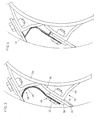
- the blade parts 36 are closer in FIGS. 3 and 4 shown. According to the depictions there, everyone is Blade part 36 into a first section 46 and a second Section 48 divided.
- the blade part 36 is made of one several millimeter thick sheet metal is formed accordingly pressed, drawn or otherwise shaped.
- the first section 46 is with the knife 34 on the Knife holder 32, d. H. whose first leg 38, attached and essentially flat. From the enlarged view of the Figures 3 and 4 will also be seen that between the head of the Screw 42 and the knife 34 a plate 50 is inserted, the the clamping forces evenly distributed on the knife 34.
- the Blade part 36 is in the area of its first section 46 clamped between the head of the screws 42 and the plate 50. To accommodate the screws 42, the blade part 36 is included holes or slots not shown.
- the first section 46 can also be between the plate 50 and the knife 34 or between the knife 34 and the first Leg 38 are provided.
- the second section 48 which according to Figure 3 with the first Section 46 in one piece and according to Figure 4 to the first section 46 connected - e.g. B. welded, soldered, riveted - is, runs curved, cranked or angled.
- the curvature runs under a more or less constant radius and lies both on the second leg 40 of the subsequent knife holder 32 and on the underside of the knife 34 held by him. Bags are thus in avoided the corner areas of the second leg 40 and in Radii converted that ensure a perfect departure of the good enable.
- the second section runs not on one sheet, but folded and covered several times also from the corner areas of the second leg 40, so that no cut goods can accumulate there.
- the blade part 36 according to FIG. 4 has an edge 52 at the end molded onto the blade part 36 on the underside of the Knife 34 supports and stabilizes.
Landscapes
- Life Sciences & Earth Sciences (AREA)
- Environmental Sciences (AREA)
- Harvester Elements (AREA)
- Threshing Machine Elements (AREA)
Claims (4)
- Tambour hacheur (12) comportant un tambour fermé (26), des porte-couteaux (32) montés sur le tambour (26), et des couteaux (34), dans lequel les porte-couteaux (32) comportent une première branche (38), qui porte le couteau (34), et une seconde branche (40), qui s'étend à partir du tambour (26) jusqu'au-dessous du couteau (34), caractérisé par une pièce formant aube (36), qui est fixée au couteau (34) et s'étend depuis un porte-couteau (32) jusque devant la seconde branche (40) du porte-couteau (32) suivant dans le sens de rotation.
- Tambour hacheur selon la revendication 1, caractérisé en ce que la pièce formant aube (36) possède une partie (46), qui s'applique indirectement ou directement sur le couteau (34) ou sur la première branche (38), et une seconde partie cintrée (48).
- Tambour hacheur selon la revendication 2, caractérisé en ce que la partie cintrée (48) possède un rayon constant.
- Tambour hacheur selon la revendication 2, caractérisé en ce que la partie cintrée (48) est cintrée et coudée de façon multiple.
Applications Claiming Priority (2)
| Application Number | Priority Date | Filing Date | Title |
|---|---|---|---|
| DE19650058 | 1996-12-03 | ||
| DE19650058A DE19650058A1 (de) | 1996-12-03 | 1996-12-03 | Häckseltrommel |
Publications (2)
| Publication Number | Publication Date |
|---|---|
| EP0846412A1 EP0846412A1 (fr) | 1998-06-10 |
| EP0846412B1 true EP0846412B1 (fr) | 2001-11-07 |
Family
ID=7813473
Family Applications (1)
| Application Number | Title | Priority Date | Filing Date |
|---|---|---|---|
| EP97121147A Expired - Lifetime EP0846412B1 (fr) | 1996-12-03 | 1997-12-02 | Rotor hacheur |
Country Status (3)
| Country | Link |
|---|---|
| US (1) | US5878970A (fr) |
| EP (1) | EP0846412B1 (fr) |
| DE (2) | DE19650058A1 (fr) |
Families Citing this family (17)
| Publication number | Priority date | Publication date | Assignee | Title |
|---|---|---|---|---|
| FR2783254B1 (fr) * | 1998-09-10 | 2000-11-10 | France Telecom | Procede d'obtention d'une couche de germanium monocristallin sur un substrat de silicium monocristallin,et produits obtenus |
| DE19918553A1 (de) | 1999-04-23 | 2000-10-26 | Deere & Co | Häckseltrommel |
| GB0007961D0 (en) * | 2000-04-01 | 2000-05-17 | Biofibres Limited | Processing fibre crops |
| DE10126280C2 (de) * | 2001-05-29 | 2003-04-17 | Krone Bernhard Gmbh Maschf | Erntemaschine |
| CA2678444C (fr) * | 2007-04-05 | 2012-05-29 | Iowa State University Research Foundation, Inc. | Dispositif de decoupe de materiau a double cisaillement |
| DE102008002172A1 (de) | 2008-06-03 | 2009-12-10 | Deere & Company, Moline | Häckseltrommelanordnung |
| US9192938B2 (en) * | 2011-01-11 | 2015-11-24 | Troy S. Grover | Knife assembly for a waste processing machine and method of assembly thereof |
| DE102012023431B4 (de) * | 2012-11-30 | 2023-11-16 | Claas Saulgau Gmbh | Messerträger für eine Häckseltrommel und Häckseltrommel für einen Feldhäcksler |
| US9538704B2 (en) * | 2013-02-15 | 2017-01-10 | Hrm Enterprises, Inc. | Horizontal rotary mower with thin replaceable blades |
| GB201306964D0 (en) * | 2013-04-17 | 2013-05-29 | Agco Int Gmbh | Cutting drum for agricultural machine |
| US10272440B2 (en) * | 2014-02-26 | 2019-04-30 | Feltron Nv | Shredding system |
| US8869498B1 (en) | 2014-04-04 | 2014-10-28 | Martin Bremmer | Handheld harvester apparatus |
| DE102016123174A1 (de) * | 2016-11-30 | 2018-05-30 | Claas Saulgau Gmbh | Häckselmesser einer Häckseltrommel eines Feldhäckslers |
| DE102017107025A1 (de) | 2017-03-31 | 2018-10-04 | Claas Saulgau Gmbh | Häckselaggregat eines Feldhäckslers und Gegenschneide für ein Häckselaggregat |
| US11224168B1 (en) | 2019-04-24 | 2022-01-18 | Martin Bremmer | Handheld harvester apparatus |
| GB202020465D0 (en) * | 2020-12-23 | 2021-02-03 | Agco Int Gmbh | Forage harvester |
| DE102021128822A1 (de) * | 2021-11-05 | 2023-05-11 | Claas Saulgau Gmbh | Häckselmesser eines Feldhäckslers und Verfahren zum Herstellen desselben |
Family Cites Families (15)
| Publication number | Priority date | Publication date | Assignee | Title |
|---|---|---|---|---|
| US1550592A (en) * | 1922-06-24 | 1925-08-18 | York Feed Machinery Company | Roughage mill |
| US2450277A (en) * | 1945-10-01 | 1948-09-28 | Allis Chalmers Mfg Co | Forage cutting apparatus, including a rotor having pocketed blades |
| US2476177A (en) | 1945-10-18 | 1949-07-12 | Allis Chalmers Mfg Co | Forage harvester knife sharpener |
| DE1507278A1 (de) | 1965-02-22 | 1970-07-02 | Landbruksteknisk Inst | Gruenfutter-Erntegeraet |
| DE2324996A1 (de) * | 1973-05-15 | 1974-12-05 | Bautz Gmbh Josef | Haeckselmaschine |
| US4011998A (en) * | 1975-10-30 | 1977-03-15 | Hesston Corporation | Forage harvester having combined cut-and-throw cylinder |
| US4061284A (en) * | 1976-09-14 | 1977-12-06 | Deere & Company | Harvester cutterhead |
| US4319718A (en) * | 1977-12-06 | 1982-03-16 | Sperry Corporation | Forage harvester cutterhead and method of sharpening |
| US4209137A (en) * | 1979-01-29 | 1980-06-24 | Sperry Rand Corporation | Forage harvester cutterhead with baffle means |
| US4257566A (en) * | 1979-07-10 | 1981-03-24 | Deere & Company | Cutterhead for forage harvesters and the like |
| DD225323A1 (de) * | 1984-07-04 | 1985-07-31 | Fortschritt Veb K | Schneidwurftrommel fuer ein haeckselaggregat |
| DE8813953U1 (de) * | 1988-11-08 | 1989-01-05 | Claas Ohg, 4834 Harsewinkel | Messertrommel eines Feldhäckslers |
| SU1709954A1 (ru) * | 1990-03-27 | 1992-02-07 | Конструкторское бюро транспортного машиностроения | Измельчитель растительного сырь |
| DE4418697C2 (de) * | 1994-05-28 | 2003-04-17 | Deere & Co | Häckselmesser und Häckselrotor |
| US5704562A (en) * | 1996-02-15 | 1998-01-06 | New Holland North America, Inc. | Cutterhead for forage harvester |
-
1996
- 1996-12-03 DE DE19650058A patent/DE19650058A1/de not_active Withdrawn
-
1997
- 1997-11-11 US US08/967,524 patent/US5878970A/en not_active Expired - Fee Related
- 1997-12-02 EP EP97121147A patent/EP0846412B1/fr not_active Expired - Lifetime
- 1997-12-02 DE DE59705264T patent/DE59705264D1/de not_active Expired - Lifetime
Also Published As
| Publication number | Publication date |
|---|---|
| US5878970A (en) | 1999-03-09 |
| DE59705264D1 (de) | 2001-12-13 |
| EP0846412A1 (fr) | 1998-06-10 |
| DE19650058A1 (de) | 1998-06-04 |
Similar Documents
| Publication | Publication Date | Title |
|---|---|---|
| EP0846412B1 (fr) | Rotor hacheur | |
| EP0508189B1 (fr) | Machine pour faucher et hacher le mais et les plantes à tige similaires | |
| EP0173224B1 (fr) | Moissoneuse-batteuse | |
| DE2425372C3 (de) | Schneidfeldhäcksler Deere & Co, Moline, 111. (V.StA.), Niederlassung Deere & Co. European Office, 6800 Mannheim | |
| DE2000605B2 (de) | 24.11.69 V.St.vAmerika 879214 Mähdrescher in Axialflußbauart Sperry Rand Corp, New Holland, Pa. (V.StA.) | |
| DE2245602A1 (de) | Schraegfoerderer fuer maehdrescher | |
| EP1106048A1 (fr) | Dispositif d'introduction et de cueillage d'un dispositif de chargement de récoltes | |
| DE1507389C3 (de) | Mähmaschine | |
| DE3048569C2 (de) | Vorrichtung zum Aufbereiten geschnittenen Halmgutes | |
| DE1507195B2 (de) | Erntemaschine für stengeliges Halmgut, insbesondere Mais | |
| EP0832553B1 (fr) | Moissonneuse-batteuse | |
| DE2917432C2 (de) | Rotierende Dresch- und Trenneinheit für Mähdrescher der Axialbauart | |
| DE3234657A1 (de) | Feldhaecksler | |
| DE3047879A1 (de) | Heuwerbungsmaschine | |
| DE2652162A1 (de) | Maehdrescher der axialflussbauart | |
| AT390164B (de) | Vorrichtung zum aufnehmen von sich auf dem boden befindlichen futter | |
| AT392194B (de) | Maschine zum ernten von mais od. dgl. stengelartigem erntegut | |
| EP0124628A1 (fr) | Moissonneuse-batteuse à dispositif de battage à écoulement axial | |
| DE2843782A1 (de) | Heuerntemaschine ohne metallzinken | |
| DE2062945C3 (de) | Maiserntegerät | |
| CH648987A5 (de) | Erntemaschine zum schwadlegen oder schwadwenden oder zum zett-wenden von schnittgut, insbesondere gras oder heu. | |
| DE19603370C2 (de) | Erntemaschine | |
| DE2922982A1 (de) | Futterhaecksler | |
| EP0139821B1 (fr) | Machine de traitement de fourrage | |
| DE2544200C3 (de) | Maschine zum Mähen und Hacksein von Mais o.dgl. stengelartigem Erntegut |
Legal Events
| Date | Code | Title | Description |
|---|---|---|---|
| PUAI | Public reference made under article 153(3) epc to a published international application that has entered the european phase |
Free format text: ORIGINAL CODE: 0009012 |
|
| AK | Designated contracting states |
Kind code of ref document: A1 Designated state(s): BE DE FR GB IT NL |
|
| AX | Request for extension of the european patent |
Free format text: AL;LT;LV;MK;RO;SI |
|
| 17P | Request for examination filed |
Effective date: 19981110 |
|
| AKX | Designation fees paid |
Free format text: BE DE FR GB IT NL |
|
| RBV | Designated contracting states (corrected) |
Designated state(s): BE DE FR GB IT NL |
|
| GRAG | Despatch of communication of intention to grant |
Free format text: ORIGINAL CODE: EPIDOS AGRA |
|
| GRAG | Despatch of communication of intention to grant |
Free format text: ORIGINAL CODE: EPIDOS AGRA |
|
| GRAH | Despatch of communication of intention to grant a patent |
Free format text: ORIGINAL CODE: EPIDOS IGRA |
|
| 17Q | First examination report despatched |
Effective date: 20010323 |
|
| RAP1 | Party data changed (applicant data changed or rights of an application transferred) |
Owner name: DEERE & COMPANY |
|
| GRAH | Despatch of communication of intention to grant a patent |
Free format text: ORIGINAL CODE: EPIDOS IGRA |
|
| GRAA | (expected) grant |
Free format text: ORIGINAL CODE: 0009210 |
|
| RIN1 | Information on inventor provided before grant (corrected) |
Inventor name: LEEB, GEORG |
|
| AK | Designated contracting states |
Kind code of ref document: B1 Designated state(s): BE DE FR GB IT NL |
|
| REF | Corresponds to: |
Ref document number: 59705264 Country of ref document: DE Date of ref document: 20011213 |
|
| REG | Reference to a national code |
Ref country code: GB Ref legal event code: IF02 |
|
| GBT | Gb: translation of ep patent filed (gb section 77(6)(a)/1977) |
Effective date: 20020114 |
|
| ET | Fr: translation filed | ||
| PLBE | No opposition filed within time limit |
Free format text: ORIGINAL CODE: 0009261 |
|
| STAA | Information on the status of an ep patent application or granted ep patent |
Free format text: STATUS: NO OPPOSITION FILED WITHIN TIME LIMIT |
|
| 26N | No opposition filed | ||
| PGFP | Annual fee paid to national office [announced via postgrant information from national office to epo] |
Ref country code: NL Payment date: 20071223 Year of fee payment: 11 |
|
| NLV4 | Nl: lapsed or anulled due to non-payment of the annual fee |
Effective date: 20090701 |
|
| PG25 | Lapsed in a contracting state [announced via postgrant information from national office to epo] |
Ref country code: NL Free format text: LAPSE BECAUSE OF NON-PAYMENT OF DUE FEES Effective date: 20090701 |
|
| PGFP | Annual fee paid to national office [announced via postgrant information from national office to epo] |
Ref country code: IT Payment date: 20091229 Year of fee payment: 13 |
|
| PGFP | Annual fee paid to national office [announced via postgrant information from national office to epo] |
Ref country code: FR Payment date: 20110107 Year of fee payment: 14 |
|
| PGFP | Annual fee paid to national office [announced via postgrant information from national office to epo] |
Ref country code: GB Payment date: 20101229 Year of fee payment: 14 |
|
| PGFP | Annual fee paid to national office [announced via postgrant information from national office to epo] |
Ref country code: BE Payment date: 20101224 Year of fee payment: 14 |
|
| PG25 | Lapsed in a contracting state [announced via postgrant information from national office to epo] |
Ref country code: IT Free format text: LAPSE BECAUSE OF NON-PAYMENT OF DUE FEES Effective date: 20101202 |
|
| BERE | Be: lapsed |
Owner name: *DEERE & CY Effective date: 20111231 |
|
| GBPC | Gb: european patent ceased through non-payment of renewal fee |
Effective date: 20111202 |
|
| REG | Reference to a national code |
Ref country code: FR Ref legal event code: ST Effective date: 20120831 |
|
| PG25 | Lapsed in a contracting state [announced via postgrant information from national office to epo] |
Ref country code: GB Free format text: LAPSE BECAUSE OF NON-PAYMENT OF DUE FEES Effective date: 20111202 Ref country code: BE Free format text: LAPSE BECAUSE OF NON-PAYMENT OF DUE FEES Effective date: 20111231 |
|
| PG25 | Lapsed in a contracting state [announced via postgrant information from national office to epo] |
Ref country code: FR Free format text: LAPSE BECAUSE OF NON-PAYMENT OF DUE FEES Effective date: 20120102 |
|
| PGFP | Annual fee paid to national office [announced via postgrant information from national office to epo] |
Ref country code: DE Payment date: 20161231 Year of fee payment: 20 |
|
| REG | Reference to a national code |
Ref country code: DE Ref legal event code: R071 Ref document number: 59705264 Country of ref document: DE |