EP0846590B1 - Procédé de réglage du moment du couple dans une système de traction Diesel-électrique et système de traction - Google Patents
Procédé de réglage du moment du couple dans une système de traction Diesel-électrique et système de traction Download PDFInfo
- Publication number
- EP0846590B1 EP0846590B1 EP97119256A EP97119256A EP0846590B1 EP 0846590 B1 EP0846590 B1 EP 0846590B1 EP 97119256 A EP97119256 A EP 97119256A EP 97119256 A EP97119256 A EP 97119256A EP 0846590 B1 EP0846590 B1 EP 0846590B1
- Authority
- EP
- European Patent Office
- Prior art keywords
- combustion engine
- driving
- power
- braking
- generator
- Prior art date
- Legal status (The legal status is an assumption and is not a legal conclusion. Google has not performed a legal analysis and makes no representation as to the accuracy of the status listed.)
- Expired - Lifetime
Links
Images


Classifications
-
- B—PERFORMING OPERATIONS; TRANSPORTING
- B60—VEHICLES IN GENERAL
- B60L—PROPULSION OF ELECTRICALLY-PROPELLED VEHICLES; SUPPLYING ELECTRIC POWER FOR AUXILIARY EQUIPMENT OF ELECTRICALLY-PROPELLED VEHICLES; ELECTRODYNAMIC BRAKE SYSTEMS FOR VEHICLES IN GENERAL; MAGNETIC SUSPENSION OR LEVITATION FOR VEHICLES; MONITORING OPERATING VARIABLES OF ELECTRICALLY-PROPELLED VEHICLES; ELECTRIC SAFETY DEVICES FOR ELECTRICALLY-PROPELLED VEHICLES
- B60L15/00—Methods, circuits, or devices for controlling the traction-motor speed of electrically-propelled vehicles
- B60L15/20—Methods, circuits, or devices for controlling the traction-motor speed of electrically-propelled vehicles for control of the vehicle or its driving motor to achieve a desired performance, e.g. speed, torque, programmed variation of speed
-
- B—PERFORMING OPERATIONS; TRANSPORTING
- B60—VEHICLES IN GENERAL
- B60K—ARRANGEMENT OR MOUNTING OF PROPULSION UNITS OR OF TRANSMISSIONS IN VEHICLES; ARRANGEMENT OR MOUNTING OF PLURAL DIVERSE PRIME-MOVERS IN VEHICLES; AUXILIARY DRIVES FOR VEHICLES; INSTRUMENTATION OR DASHBOARDS FOR VEHICLES; ARRANGEMENTS IN CONNECTION WITH COOLING, AIR INTAKE, GAS EXHAUST OR FUEL SUPPLY OF PROPULSION UNITS IN VEHICLES
- B60K6/00—Arrangement or mounting of plural diverse prime-movers for mutual or common propulsion, e.g. hybrid propulsion systems comprising electric motors and internal combustion engines
- B60K6/20—Arrangement or mounting of plural diverse prime-movers for mutual or common propulsion, e.g. hybrid propulsion systems comprising electric motors and internal combustion engines the prime-movers consisting of electric motors and internal combustion engines, e.g. HEVs
- B60K6/42—Arrangement or mounting of plural diverse prime-movers for mutual or common propulsion, e.g. hybrid propulsion systems comprising electric motors and internal combustion engines the prime-movers consisting of electric motors and internal combustion engines, e.g. HEVs characterised by the architecture of the hybrid electric vehicle
- B60K6/46—Series type
-
- B—PERFORMING OPERATIONS; TRANSPORTING
- B60—VEHICLES IN GENERAL
- B60L—PROPULSION OF ELECTRICALLY-PROPELLED VEHICLES; SUPPLYING ELECTRIC POWER FOR AUXILIARY EQUIPMENT OF ELECTRICALLY-PROPELLED VEHICLES; ELECTRODYNAMIC BRAKE SYSTEMS FOR VEHICLES IN GENERAL; MAGNETIC SUSPENSION OR LEVITATION FOR VEHICLES; MONITORING OPERATING VARIABLES OF ELECTRICALLY-PROPELLED VEHICLES; ELECTRIC SAFETY DEVICES FOR ELECTRICALLY-PROPELLED VEHICLES
- B60L50/00—Electric propulsion with power supplied within the vehicle
- B60L50/10—Electric propulsion with power supplied within the vehicle using propulsion power supplied by engine-driven generators, e.g. generators driven by combustion engines
-
- B—PERFORMING OPERATIONS; TRANSPORTING
- B60—VEHICLES IN GENERAL
- B60L—PROPULSION OF ELECTRICALLY-PROPELLED VEHICLES; SUPPLYING ELECTRIC POWER FOR AUXILIARY EQUIPMENT OF ELECTRICALLY-PROPELLED VEHICLES; ELECTRODYNAMIC BRAKE SYSTEMS FOR VEHICLES IN GENERAL; MAGNETIC SUSPENSION OR LEVITATION FOR VEHICLES; MONITORING OPERATING VARIABLES OF ELECTRICALLY-PROPELLED VEHICLES; ELECTRIC SAFETY DEVICES FOR ELECTRICALLY-PROPELLED VEHICLES
- B60L50/00—Electric propulsion with power supplied within the vehicle
- B60L50/10—Electric propulsion with power supplied within the vehicle using propulsion power supplied by engine-driven generators, e.g. generators driven by combustion engines
- B60L50/15—Electric propulsion with power supplied within the vehicle using propulsion power supplied by engine-driven generators, e.g. generators driven by combustion engines with additional electric power supply
-
- B—PERFORMING OPERATIONS; TRANSPORTING
- B60—VEHICLES IN GENERAL
- B60W—CONJOINT CONTROL OF VEHICLE SUB-UNITS OF DIFFERENT TYPE OR DIFFERENT FUNCTION; CONTROL SYSTEMS SPECIALLY ADAPTED FOR HYBRID VEHICLES; ROAD VEHICLE DRIVE CONTROL SYSTEMS FOR PURPOSES NOT RELATED TO THE CONTROL OF A PARTICULAR SUB-UNIT
- B60W10/00—Conjoint control of vehicle sub-units of different type or different function
- B60W10/18—Conjoint control of vehicle sub-units of different type or different function including control of braking systems
-
- B—PERFORMING OPERATIONS; TRANSPORTING
- B60—VEHICLES IN GENERAL
- B60L—PROPULSION OF ELECTRICALLY-PROPELLED VEHICLES; SUPPLYING ELECTRIC POWER FOR AUXILIARY EQUIPMENT OF ELECTRICALLY-PROPELLED VEHICLES; ELECTRODYNAMIC BRAKE SYSTEMS FOR VEHICLES IN GENERAL; MAGNETIC SUSPENSION OR LEVITATION FOR VEHICLES; MONITORING OPERATING VARIABLES OF ELECTRICALLY-PROPELLED VEHICLES; ELECTRIC SAFETY DEVICES FOR ELECTRICALLY-PROPELLED VEHICLES
- B60L2200/00—Type of vehicles
- B60L2200/26—Rail vehicles
-
- B—PERFORMING OPERATIONS; TRANSPORTING
- B60—VEHICLES IN GENERAL
- B60W—CONJOINT CONTROL OF VEHICLE SUB-UNITS OF DIFFERENT TYPE OR DIFFERENT FUNCTION; CONTROL SYSTEMS SPECIALLY ADAPTED FOR HYBRID VEHICLES; ROAD VEHICLE DRIVE CONTROL SYSTEMS FOR PURPOSES NOT RELATED TO THE CONTROL OF A PARTICULAR SUB-UNIT
- B60W2710/00—Output or target parameters relating to a particular sub-units
- B60W2710/06—Combustion engines, Gas turbines
- B60W2710/0644—Engine speed
- B60W2710/065—Idle condition
-
- Y—GENERAL TAGGING OF NEW TECHNOLOGICAL DEVELOPMENTS; GENERAL TAGGING OF CROSS-SECTIONAL TECHNOLOGIES SPANNING OVER SEVERAL SECTIONS OF THE IPC; TECHNICAL SUBJECTS COVERED BY FORMER USPC CROSS-REFERENCE ART COLLECTIONS [XRACs] AND DIGESTS
- Y02—TECHNOLOGIES OR APPLICATIONS FOR MITIGATION OR ADAPTATION AGAINST CLIMATE CHANGE
- Y02T—CLIMATE CHANGE MITIGATION TECHNOLOGIES RELATED TO TRANSPORTATION
- Y02T10/00—Road transport of goods or passengers
- Y02T10/60—Other road transportation technologies with climate change mitigation effect
- Y02T10/62—Hybrid vehicles
-
- Y—GENERAL TAGGING OF NEW TECHNOLOGICAL DEVELOPMENTS; GENERAL TAGGING OF CROSS-SECTIONAL TECHNOLOGIES SPANNING OVER SEVERAL SECTIONS OF THE IPC; TECHNICAL SUBJECTS COVERED BY FORMER USPC CROSS-REFERENCE ART COLLECTIONS [XRACs] AND DIGESTS
- Y02—TECHNOLOGIES OR APPLICATIONS FOR MITIGATION OR ADAPTATION AGAINST CLIMATE CHANGE
- Y02T—CLIMATE CHANGE MITIGATION TECHNOLOGIES RELATED TO TRANSPORTATION
- Y02T10/00—Road transport of goods or passengers
- Y02T10/60—Other road transportation technologies with climate change mitigation effect
- Y02T10/64—Electric machine technologies in electromobility
-
- Y—GENERAL TAGGING OF NEW TECHNOLOGICAL DEVELOPMENTS; GENERAL TAGGING OF CROSS-SECTIONAL TECHNOLOGIES SPANNING OVER SEVERAL SECTIONS OF THE IPC; TECHNICAL SUBJECTS COVERED BY FORMER USPC CROSS-REFERENCE ART COLLECTIONS [XRACs] AND DIGESTS
- Y02—TECHNOLOGIES OR APPLICATIONS FOR MITIGATION OR ADAPTATION AGAINST CLIMATE CHANGE
- Y02T—CLIMATE CHANGE MITIGATION TECHNOLOGIES RELATED TO TRANSPORTATION
- Y02T10/00—Road transport of goods or passengers
- Y02T10/60—Other road transportation technologies with climate change mitigation effect
- Y02T10/7072—Electromobility specific charging systems or methods for batteries, ultracapacitors, supercapacitors or double-layer capacitors
-
- Y—GENERAL TAGGING OF NEW TECHNOLOGICAL DEVELOPMENTS; GENERAL TAGGING OF CROSS-SECTIONAL TECHNOLOGIES SPANNING OVER SEVERAL SECTIONS OF THE IPC; TECHNICAL SUBJECTS COVERED BY FORMER USPC CROSS-REFERENCE ART COLLECTIONS [XRACs] AND DIGESTS
- Y02—TECHNOLOGIES OR APPLICATIONS FOR MITIGATION OR ADAPTATION AGAINST CLIMATE CHANGE
- Y02T—CLIMATE CHANGE MITIGATION TECHNOLOGIES RELATED TO TRANSPORTATION
- Y02T10/00—Road transport of goods or passengers
- Y02T10/60—Other road transportation technologies with climate change mitigation effect
- Y02T10/72—Electric energy management in electromobility
-
- Y—GENERAL TAGGING OF NEW TECHNOLOGICAL DEVELOPMENTS; GENERAL TAGGING OF CROSS-SECTIONAL TECHNOLOGIES SPANNING OVER SEVERAL SECTIONS OF THE IPC; TECHNICAL SUBJECTS COVERED BY FORMER USPC CROSS-REFERENCE ART COLLECTIONS [XRACs] AND DIGESTS
- Y10—TECHNICAL SUBJECTS COVERED BY FORMER USPC
- Y10S—TECHNICAL SUBJECTS COVERED BY FORMER USPC CROSS-REFERENCE ART COLLECTIONS [XRACs] AND DIGESTS
- Y10S903/00—Hybrid electric vehicles, HEVS
- Y10S903/902—Prime movers comprising electrical and internal combustion motors
- Y10S903/903—Prime movers comprising electrical and internal combustion motors having energy storing means, e.g. battery, capacitor
- Y10S903/947—Characterized by control of braking, e.g. blending of regeneration, friction braking
Definitions
- the invention relates to a method for regulating the drag torque in a vehicle in detail with the features from the preamble of Claim 1 (see. DE 195 23 985 A) also a drive system according to the preamble of Claim 18 (cf. DE 44 35 613 C).
- Conventional drive trains of vehicles include at least one prime mover, especially one Internal combustion engine, as well as torque transmission and Conversion devices which are coupled to the output.
- the internal combustion engine via a clutch with a Gear can be coupled, the output of which is at least indirectly via further power-transmitting components in connection with the drive wheels can stand.
- the driver's desire to accelerate the vehicle is via an actuating device which, for example, as a drive lever or Pedal can be implemented.
- the actuator in turn, at least indirectly with the power actuator Drive machine coupled.
- the wheels are driven by power transmission from the prime mover via the clutch and the gearbox to the Drive wheels.
- the Internal combustion engine generated power to the drive wheels be transmitted.
- a first part of the performance of the Internal combustion engine generated power is there for overcoming the resistances adhering to the overall system, especially the internal ones Resistors of the internal combustion engine and the power transmitting Components required. Only the second part of the service can then to accelerate or maintain a certain speed of the Vehicle can be used.
- the actuator is generally directly connected to the Power actuator of the internal combustion engine coupled.
- the driver may be his desire to accelerate or hold one express a certain speed. Does the driver give that The accelerator pedal or the drive lever is completely free, is adjusted on Power actuator such that in addition to the first power share Maintenance of idle operation no additional second Power share is generated more.
- Driving torque effective. That is the moment when there is relief Accelerator pedal or lever when the vehicle is rolling due to this kinetic energy on the wheel effective and introduced into the drive train becomes. Part of the driving torque acting on the wheels is in the Drive train initiated, which drives the drive machine from the output side, i.e. the wheels.
- Diesel-electric Drive systems with diesel-electric show a different behavior Drive configurations. These include a diesel engine Drive machine, a mechanically connectable to the drive machine and electrical machine operable as a generator, and at least one, at least one drive wheel at least indirectly driving an electric motor, which can be electrically coupled to the electrical machine.
- a diesel-electric drive system is the one that acts on the drive wheels Drag torque, as is the case with a mechanical drive train not necessarily due to the mechanical decoupling given.
- An automatic fuel saving due to the driving behavior is not possible because the internal combustion engine must release the Accelerator pedals are still operated at least in idle.
- the invention is therefore based on the object of a method for Influencing or regulating the drag torque of a vehicle a drive system comprising an internal combustion engine generator arrangement, to develop in which a fuel-optimized Driving behavior analogous to the conventional drive systems with possible simple means and inexpensive.
- the constructive as well as control or regulatory expenditure is to be kept low.
- Drag torque generated and set which is always sufficient to to put the internal combustion engine in the push mode and this with which to trigger the overrun cut-off by means of a corresponding the control associated with the internal combustion engine Operating speed.
- the drive wheels at least indirectly driving electric motors, which preferably as Transverse flux machine are executed with the accelerator pedal or unloaded Lever and / or when actuating a device to activate the function Drag torque control or regulation in generator mode operated.
- the drive train is connected to the Power taken from drive wheels and as an internal combustion engine trained engine.
- the supply takes place via the electrical coupling between those designed as electric motors Wheel drive motors and the one that can be operated as a generator and the Internal combustion engine downstream electrical machine whose Operation in this case for the purpose of driving the Internal combustion engine motorized, to the prime mover. there however, only a certain one, through the generator operation of the Drive wheels at least indirectly driving electric motors removable first share of performance used.
- This share of performance is at least always so large that the internal combustion engine is operated at a speed which is equal to or greater than the idle speed of the Internal combustion engine is backed up.
- the size of this speed is in this case by a controller assigned to the internal combustion engine, which stops the fuel supply when this speed is reached, dependent. This speed can be determined by that of the internal combustion engine assigned control can be fixed unchangeable or changeable.
- At least a first share of performance that is required to at least the Realizing idle operation is therefore carried out by the generator Electric motors delivered to the internal combustion engine.
- the as the driving motor of the Wheels functioning electric motor or the drive motors on the wheels Power drawn in generator operation can be used for this in order to operate the electrical machine as a generator Bring internal combustion engine into the push mode, whereby the Fuel consumption that would otherwise be required around the engine, i.e.
- the inventive generation offers a Drag torque and its control or regulation the possibility at Always release the accelerator pedal or lever the internal combustion engine to put in the push mode, with which a fuel cut-off is possible will, and thus reduce fuel consumption.
- the solution according to the invention is when traveling in the plane and on slopes the powertrain only the power that can be operated as a generator Taken electric motors, which is just enough to at least the To ensure idle operation of the engine and the To bring fuel delivery for the internal combustion engine to zero, when driving in the plane or on inclines through the Power supply to the internal combustion engine limited reduction the kinetic energy of the vehicle only imperceptible delays Vehicle.
- the drive wheels are preferably at least indirectly driving Electric motors and / or those that can be operated in generator mode electrical machine designed as transverse flux machines.
- the wheels are driven by at least one electric motor. Whose generated power can then be divided between both wheels. A Assignment of an electric motor to a wheel is also possible conceivable.
- a preferred further development of the solution according to the invention provides at least for the downhill ride, to regulate the drag torque in this way, that the vehicle speed at the time of the discharge of the Accelerator pedal measured value is limited.
- the drag torque control is - at least for the downhill ride - part of the regulation constant driving speed.
- the vehicle control tries in this Case, the speed detected at the time the function was selected by appropriately metered brake intervention in the subordinate to it Organs not to exceed. That the generator operated As much power is withdrawn from electric motors as in addition to the Maintenance of idle operation or operation with the Thrust cut-off required speed to reduce or Constant driving speed is required.
- a definable one Acceleration or deceleration is not speed to be set as a benchmark but a definable one Acceleration or deceleration.
- a defined one Acceleration e.g. can depend on the driving speed, be allowed.
- a control or regulating device is assigned to the drive system. This can be part of a central driving control.
- the control device comprises at least one control device which has at least one first and one second input and at least one first output.
- This first input is coupled to a device for at least indirectly detecting the actuation state of the actuating member for specifying a driver's request with regard to a specific speed or acceleration.
- the actuator can for example be in the form of an accelerator pedal or lever.
- the second input is coupled to a device for detecting a variable that at least indirectly describes the current driving speed.
- the Drag torque in the drive train controlled and adjusted.
- the the Drive wheels through the generator operation of these driving Electric motors removed and attached to the electrical machine passed on performance must always be so great that the Internal combustion engine supplied drive power is sufficient at least at idle or at least at the speed from which the Thrust shutdown starts to operate. Accordingly, on Output of the control or regulating device an actuating signal to control the Supply to consumers, here the internal combustion engine, or these assigned units, preferably the electrical coupling, output.
- a further braking device can for example in the form of a mechanical or a hydraulic Brake device to be executed. Priority can be given to actuation the drag torque regulation are granted. It is when actuated the further braking device either for the time being Drag torque control decommissioned in such a way that only the idle operation of the engine is maintained, or but the drag torque control is in its setting at the time the actuation of the other braking device. In the latter The case may be that generated by means of the drag torque control Braking torque corresponding to the actuation of the others Braking device to be generated braking torque are superimposed.
- the braking device then generates an additional braking torque, which leads to a reduction in driving speed.
- additional braking torque which leads to a reduction in driving speed.
- Other options the combination or assignment of both braking torques are conceivable.
- the after the actuation of the further additional braking device has ended The actual speed is used as the new setpoint i.e. as new Command variable of the control set or saved.
- the one to be created Drag torque is then adjusted according to this speed and settled. This allows the driver to operate the device significantly relieved and otherwise required additional adjustments Actuation, for example, of a foot pedal or hand lever for holding or Correction of the speed can be omitted.
- Another design option is when you select the further braking device a maximum selection between that by the Drag torque control generated braking torque and with the to meet further braking device generated braking torque.
- the inventive method of drag torque control as Function can be activated when the driver actuates the actuator, for example the accelerator pedal or the drive lever - relieved and / or when the driver operates a device by means of which he makes his wish Activation of the drag torque control of the electronic Vehicle control can announce.
- This function can be deactivated with a subsequent actuation of the accelerator pedal or lever and / or a deactivation of the device by means of which he wishes to Activation of the drag torque control of the electronic Vehicle control can be made.
- the activation or deactivation of the function of the Drag torque control is preferably not carried out abruptly Actuation or relief of the actuators or facilities. This can be implemented using a programmed function, for example, which makes a smooth transition with respect to the before or after in Drive train prevailing drive torque at the moment which the Drag torque control generated, allowed.
- Drag torque or drive torque can also be such be realized that already at a certain angular position of the Accelerator pedal or lever, which is not equal to the end position, that of Driver desired drive torque by controlling the Power actuator of the internal combustion engine is zero.
- This certain angular position up to the end position of the accelerator pedal or Lever takes the torque generated by the drag torque control continuously increasing.
- This process also runs analogously when the Drag torque control, i.e. for example, when you press the Accelerator pedal or lever.
- the specific Angle position of the accelerator pedal or lever depending on various variables influencing the driving state, for example the Driving speed, to be preset or each time it is pressed set.
- a certain angular position can also be predetermined, which can be changed in size for example by a factor is.
- transition to activation / deactivation of the This means that drag torque control cannot be carried out suddenly characterized that this transition taking into account the speed of the Internal combustion engine is performed.
- the speed of the internal combustion engine is such that at one Speed of the internal combustion engine, which is significantly above the Idling or the speed is the one in push mode Thrust cutout triggers, the transition to function Drag torque control takes place with a delay.
- Drag torque regulation in further regulations, for example one Control to constant driving speed, to be included.
- the Drag torque control and the combined drag torque control with the actuation of further braking devices also with the Speed limit regulation by reducing the Internal combustion engine can be combined.
- the priority of the individual Control systems can meet the operational requirements and the desired driving behavior are determined,
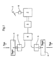
- FIG. 1 illustrates a diesel-electric one in a simplified representation Drive system and power transmission.
- a drive system 1 comprises at least one engine, here in the form of a diesel engine executed internal combustion engine 2, one with the Internal combustion engine 2 mechanically coupled, when driving as Generator-operated electrical machine 3, at least one Drive wheel 4 at least indirectly driving another electric motor 5, the electrically with the electrical machine 3 that can be operated as a generator is coupled.
- This electrical coupling, here designated 6, can for example via a DC link.
- the electrical machine 3 and the electric motor 5 are preferably as Transversal flux machine trained.
- the electric motor 5 can be as shown be arranged so that this as a direct drive for the drive wheel 4th acts. However, it is also a division of benefits over corresponding ones Transfer case conceivable on both drive wheels.
- the power P AM to be applied is composed of at least a first power component P AM1 and a second power component P AM2 .
- the first power component is the part that is required to overcome the inherent resistances of the internal combustion engine and to be able to operate it at idling speed.
- the second power component is the part that serves to accelerate the vehicle or to maintain a certain constant speed.
- the torque M AR generated on the drive wheels can essentially be derived from this.
- This second mechanical power component applied by the internal combustion engine 2 is converted by the electrical machine 3, which can be operated as a generator, into electrical power, which in turn is fed to the electric motor 5 via the electrical coupling 6 and thus to the drive wheels 4.
- An actuating element for example in the form of an accelerator pedal or lever 7 or a differently designed control element, with which the driver's wish regarding a certain driving behavior can be expressed, is coupled to a power actuator 8 of the internal combustion engine 2.
- a power actuator 8 of the internal combustion engine 2 acts as the power actuator.
- the power actuator 8 of the internal combustion engine 2 is adjusted such that the idle operation of the internal combustion engine 2, ie the idle speed n motleer is just maintained.
- the electric motors 5 driving the drive wheels are operated in generator mode when the accelerator pedal 7 is released after acceleration or deceleration, and the power generated by the electric motors 5 and extracted from the drive wheels is used to drive the internal combustion engine 2 via the to drive electrical coupling 6 and the electrical machine 3, which is then operated in motor operation.
- the aim is to achieve the pushing operation of the internal combustion engine.
- the vehicle When driving on a slope, the vehicle has an increasing kinetic energy E kin after releasing the accelerator pedal or lever 7 due to the downhill force, which results in an increase in the driving torque M Fahr .
- this can also be implemented when driving on a plane.
- the power actuator 8 is also reset so that only the internal combustion engine is still operated at idle.
- at least a first power component is withdrawn from the vehicle, in particular the drive wheels 4, by the generator operation of the electric motors 5, which is just sufficient to bring the internal combustion engine 2 into overrun operation.
- this first power component is so small that only an imperceptible deceleration of the vehicle when driving in the plane is achieved.
- This first power component to be extracted from the drive wheels 4 increases at very low speeds with an increase in speed until a certain speed is reached, from which power can be drawn in such a way that an overrun cut-off is always achieved and at the same time the driving speed is only slightly reduced becomes.
- FIGS. 2 and 3 in contrast to one another, illustrate the course of the drag torque in conventional mechanical drive trains and in a diesel-electric drive system operated according to the invention.
- the drag torque and power curve M towing or P towing are each plotted in a diagram as a function of the driving speed V vehicle or the speed of the drive wheels n AR .
- the solution according to the invention enables Saving fuel without much additional constructive and tax and control engineering effort with imperceptible delay when driving in the Level and with corresponding drag torque control Keeping the driving speed constant when driving downhill.
- FIGS. 3a and 3b show the trajectories according to the invention of the drag torque M drag and the drag power P drag in the plane and on the slope.
- FIGS 3a and 3b illustrate that according to the invention, with increasing driving speed, an increasing towing moment M towing or a towing power P towing is first generated, which is just sufficient from a certain speed V vehicle-A to bring the internal combustion engine into overrun operation and thus the Trigger overrun cut-off. From this driving speed, as it increases, at least only this drag torque M drag 1 sufficient for pushing operation is generated.
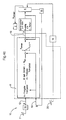
- FIGS 4a to 4c illustrate with the help of block diagrams Implementation of the method required tax or. Control devices and how they work. For the same items uses the same reference numerals.
- FIG. 4a illustrates a control device 10. This processes at least two input variables.
- a first input variable A is formed by a variable that at least indirectly characterizes the operating state of the actuating member 7 and / or a device for specifying the driver's request.
- the variable that characterizes the actuation state of the actuation element 7 is preferably the angular position of the accelerator pedal or lever 7.
- a second input variable B is determined by a variable that at least indirectly describes the current driving state at the time the actuation element 7 is released and / or the activation or activation of a device formed to specify a driver request. This quantity can, for example, the current driving speed v be.
- the control device has at least one control device 11 with at least two inputs for the input variables A and B - a first input 12 and a second input 13.
- the first input 12 can be coupled to a device 14 for detecting the actuation state of the actuating member 7
- the second input can be connected to a device 15 for detecting a variable describing the current driving state.
- This device 15 can for example be designed as a speed measuring device.
- a drag torque to be generated is determined as a function of the variable B, preferably the driving speed, which characterizes the driving state at least indirectly. This corresponds to the power to be extracted from the drive train, in particular the drive wheels 4. It should be noted here that at very low speeds, a reduction in output on the drive wheels 4 would not be sufficient to bring the internal combustion engine into overrun mode. Furthermore, a complete reduction in performance can lead to the complete braking of the vehicle, which is not the purpose. For this reason, a drag torque is assigned in such a way that, at low speeds, the increasing drag torque is generated with their increase, which from a certain speed is always sufficient to bring the internal combustion engine into overrun mode.
- control or regulating device has an output 16, which is coupled to the consumers or the electric motors and / or the electrical coupling 6 for the purpose of setting the power to be extracted from the drive wheels 4 - at least the first power component P Schlepp1 - and at which a manipulated variable Y for setting a specific towing moment M towing or a specific towing power P towing is output.
- FIG. 4b shows a block diagram for a drag torque control with a constant speed function on a downhill gradient.
- the control device 10 has the same inputs A and B - as described in FIG. 4a.
- the variable which characterizes the current driving state and is determined at the time when the device or release of the accelerator pedal or lever 7 is actuated is set as a control variable W of a control system.
- This variable is preferably a speed W vsoll determined from the current speed at this time, but can also be an acceleration. This is set using the information contained in the control path drag torque control, ie it is carried out a continuous comparison of the command variable w v vsoll with the continuously determined actual value.
- the second power component P tow2 which is to be used to brake the vehicle, and accordingly the total drag power to be generated and thus the total power to be extracted from the drive wheels by the generator Operation of the electric motors 4 set.
- the second power component P Schlepp2 can be converted into heat or stored in a storage device.
- the drag torque control is used to control the constant driving speed when driving downhill and is part of this. In a further embodiment according to FIG. 4c, if there is a further braking device, here designated 19 and its actuating device 20, this can additionally be activated during the drag torque control.
- the actual speed which is present after the actuation of the braking device has ended or the variable which at least indirectly characterizes the current driving state is then assigned to the setpoint input of the control system.
- Both - the electric motors 5 and the braking device 19 are preferably assigned the same control and regulating device 10.
- the individual control processes are preferably carried out in the control or.
- Control device to be implemented programmable functions.
- the automatic resetting or assignment of the target value, ie the reference variable of the control loop, can take place, for example, by means of appropriately programmed algorithms. Electrical circuits and logic gates are also conceivable.
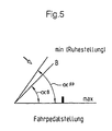
- Figure 5 illustrates an advantageous embodiment to avoid a sudden transition between drive torque and drag torque when activating the drag torque control or between drag torque and drive torque when deactivated.
- the transition should preferably be smooth. This can be implemented using programmable functions.
- the angle adjustment on the actuating member, ie on the accelerator pedal or lever 7, can be used as the basis for realizing a smooth transition.
- a certain accelerator pedal angle alpha B which characterizes a certain accelerator pedal position B that is not equal to the possible end positions of release or depression, is used to adjust the power actuator 8 on the internal combustion engine 2 at an earlier point in time when the accelerator pedal 7 is not yet complete was released to the effect that the drive power generated by the internal combustion engine becomes zero and the internal combustion engine is only operated in idle mode. From this point in time until the end position, which signals the release of the accelerator pedal, is reached, a gradual transition to the drag torque to be set takes place, for example, by means of a programmable function.
Landscapes
- Engineering & Computer Science (AREA)
- Transportation (AREA)
- Mechanical Engineering (AREA)
- Power Engineering (AREA)
- Chemical & Material Sciences (AREA)
- Combustion & Propulsion (AREA)
- Electric Propulsion And Braking For Vehicles (AREA)
- Hybrid Electric Vehicles (AREA)
- Control Of Vehicle Engines Or Engines For Specific Uses (AREA)
Claims (27)
- Procédé destiné à influencer le couple de glissement dans une ligne de transmissiondans lequelavec au moins un électromoteur (5) entraínant au moins indirectement une roue motrice ;avec un moteur à combustion interne (2) ;avec une machine électrique (3) apte à être couplée mécaniquement avec le moteur à combustion interne (2) et à être actionnée en générateur ou en moteur ;chaque électromoteur (5) est apte à être couplé électriquement avec le générateur (3) ;avec un organe de commande (7) couplé au moins indirectement avec un organe de réglage (8) du moteur à combustion interne (2) et/ou un dispositif de présentation d'un souhait du conducteur quant au déplacement du véhicule ;1.1 les électromoteurs (5) sont actionnés en régime générateur au moins en cas de libération de l'organe de commande (7) et/ou lors de l'actionnement du dispositif de présentation d'un souhait du conducteur,1.2 une première quantité de puissance produite par générateur est prélevée sur les roues motrices (4) par l'intermédiaire des électromoteurs (5),1.3 cette première quantité de puissance est amenée à la machine électrique (3) pour entraíner le moteur à combustion interne (2),
caractérisé par les particularités suivantes :1.4 la première quantité de puissance est choisie de manière que le moteur à combustion interne (2) soit entraíné à une vitesse supérieure ou égale à la vitesse à vide, vitesse à laquelle il se produit une interruption totale de l'alimentation en carburant au moyen d'une commande affectée au moteur à combustion interne (2). - Procédé selon la revendication 1,
caractérisé par les particularités suivantes :2.1 une grandeur caractérisant au moins indirectement l'état de marche au moment considéré est déterminée au moins à partir de l'instant où la pédale d'accélérateur (7) est relâchée ou le mécanisme actionné, en au moins une pluralité d'intervalles de temps qui peuvent être déterminés,2.2 la valeur déterminée de la grandeur caractérisant au moins indirectement l'état de marche du moment à l'instant de la libération de l'organe de commande (7) et/ou de l'actionnement du dispositif de présentation d'un souhait du conducteur relatif à l'état de marche au moment considéré, est posée comme valeur de consigne de réglage.2.3 la valeur de consigne est comparée à la valeur réelle ;2.4 en cas d'un écart entre la valeur réelle et la valeur de consigne, en ce sens que la valeur réelle est supérieure à la valeur de consigne, une seconde quantité de puissance additionnelle est prélevée sur les roues motrices (4) au moyen des électromoteurs (5) fonctionnant en générateur, afin de produire un couple de freinage. - Procédé selon la revendication 2, caractérisé en ce que la vitesse de marche est choisie comme grandeur caractérisant au moins indirectement l'état de marche au moment considéré.
- Procédé selon la revendication 2, caractérisé en ce que l'accélération est choisie comme grandeur décrivant au moins indirectement l'état de marche au moment considéré.
- Procédé selon l'une des revendications 1 à 4, caractérisé par les particularités suivantes :5.1 il est prévu au moins un autre mécanisme de freinage apte à être actionné ;5.2 au moins une grandeur décrivant au moins indirectement l'état de marche au moment considéré est déterminée au moins à partir de l'instant où le mécanisme de freinage est désactivé, en au moins une pluralité d'intervalles de temps pouvant être déterminés ;5.3 la grandeur présente au moment de la désactivation est posée comme nouvelle valeur de consigne d'un réglage ;5.4 la valeur de consigne est comparée avec la valeur réelle ;5.5 en cas d'un écart entre la valeur réelle et la valeur de consigne, en ce sens que la valeur réelle est supérieure à la valeur de consigne, une deuxième quantité additionnelle de puissance est prélevée sur les roues motrices (4) au moyen des électromoteurs (5) fonctionnant en générateur, afin de produire un couple de freinage.
- Procédé selon la revendication 5, caractérisé en ce que lors de l'activation d'au moins un autre mécanisme de freinage, le réglage du couple de glissement est désactivé, en ce sens que les quantités de puissance prélevées sur les roues motrices à l'instant de l'activation du mécanisme de freinage continuent d'être prélevées sans changement et qu'il se produise un couple de freinage supplémentaire avec le mécanisme de freinage.
- Procédé selon la revendication 6, caractérisé en ce que la deuxième quantité de puissance prélevée sur les roues motrices et le couple de freinage produit par le mécanisme de freinage se superposent et s'additionnent.
- Procédé selon la revendication 6, caractérisé en ce qu'il se produit avec le mécanisme de freinage un couple de freinage qui résulte de la différence entre le couple de freinage recherché correspondant à l'actionnement du mécanisme de freinage et le couple correspondant à la deuxième quantité de puissance.
- Procédé selon la revendication 5, caractérisé en ce que lors de l'activation d'au moins un autre mécanisme de freinage, le réglage du couple de glissement est désactivé en ce sens que seule la première quantité de puissance est prélevée sur les roues motrices à partir de l'activation du mécanisme de freinage et qu'un couple de freinage n'est produit qu'avec le mécanisme de freinage.
- Procédé selon la revendication 5, caractérisé en ce qu'il est fait un choix maximal entre la deuxième quantité de puissance prélevée sur les roues motrices (4) à l'instant de l'activation du mécanisme de freinage et le couple de freinage recherché correspondant à l'actionnement du mécanisme de freinage, et que par conséquent le couple de freinage est produit seulement avec l'un ou l'autre des deux systèmes.
- Procédé selon l'une des revendications 1 à 10, caractérisé en ce que le passage du couple d'entraínement au couple de glissement et inversement s'effectue sans à coups.
- Procédé selon la revendication 11, caractérisé en ce que dès l'instant de la libération de la pédale d'accélérateur ou du levier (7) de vitesse et/ou d'actionnement d'un dispositif de présentation d'un souhait du conducteur pour commander les organes de réglage pour influencer la puissance à prélever sur les roues motrices (4), une routine programmée est déroulée.
- Procédé selon l'une des revendications 11 ou 12, caractérisé par les particularités suivantes :13.1 une position déterminée qui n'est pas l'une des deux positions extrêmes, est définie au niveau de l'organe de commande ;13.2 lorsque cette position déterminée est atteinte, l'organe de réglage de puissance du moteur à combustion interne (2) est réglé de telle sorte que la puissance d'entraínement produite par le moteur à combustion (2) interne soit égale à zéro ;13.3 lors du balayage du domaine allant de cette position déterminée à la position extrême et inversement, le couple de glissement à régler est progressivement augmenté ou réduit.
- Procédé selon la revendication 13, caractérisé en ce que la définition de la position est constamment renouvelée.
- Procédé selon la revendication 13, caractérisé en ce que la définition de la position peut être prédéfinie de manière fixe.
- Procédé selon l'une des revendications 11 à 14, caractérisé en ce que le passage du couple d'entraínement au couple de glissement et inversement s'effectue en fonction de la vitesse du moteur à combustion interne (2).
- Procédé selon la revendication 16, caractérisé en ce que lors d'un écart que l'on peut déterminer, entre la vitesse du moteur à combustion interne (2) au moment considéré et la vitesse à partir de laquelle une coupure d'alimentation en poussée peut être entreprise, le passage du, ou vers le, réglage du couple de glissement s'effectue de manière différée.
- Unité d'entraínement pour un véhicule :18.1 avec au moins un électromoteur (5) entraínant au moins indirectement une roue motrice (4) ;18.2 avec un moteur à combustion interne (2) ;18.3 avec une machine électrique (3) apte à être couplée mécaniquement avec le moteur à combustion interne (2) et apte à être actionnée en générateur ou en moteur ;18.4 chaque électromoteur (5) est apte à être couplé électriquement avec la machine électrique (3) qui peut être actionnée en générateur ;18.5 avec un organe de commande (7) pouvant être couplé au moins indirectement avec un organe de réglage (8) du moteur à combustion interne (2) et/ou un dispositif de présentation d'un souhait du conducteur quant au déplacement du véhicule ;18.6 avec une unité de réglage (10) ou de commande comprenant un dispositif de commande (11) avec au moins une première entrée (12), une deuxième entrée (13) et une première sortie (16) ;18.7 la première entrée (12) est couplée avec l'organe de commande (7) ;18.8 la deuxième entrée (13) est couplée avec au moins un dispositif d'enregistrement (15) d'une grandeur décrivant au moins indirectement l'état de marche au moment considéré ;
caractérisé en ce que :18.9 la première sortie (16) est couplée au moins avec un organe de réglage destiné à régler à la fois la puissance à prélever sur les roues motrices (4) en régime générateur de l'électromoteur (5) et la première quantité de puissance à apporter au moteur à combustion interne (2) ;18.10 il est prévu des moyens de détermination des grandeurs de réglage (Y). - Unité d'entraínement selon la revendication 18, caractérisée en ce que le moyen est une fonction programmable.
- Unité d'entraínement selon la revendication 18, caractérisée en ce que le moyen est un circuit électronique.
- Unité d'entraínement selon l'une des revendications 18 à 20, caractérisée par les particularités suivantes :21.1 le dispositif de réglage comprend un dispositif de comparaison pour comparer une valeur pouvant être préétablie et servant de valeur de consigne pour une grandeur caractérisant l'état de marche au moment considéré, avec la valeur réelle au moment considéré ;21.2 il est prévu au moins un dispositif de coordination subordonné au dispositif de comparaison qui détermine une nouvelle quantité de puissance additionnelle à prélever encore sur les roues motrices et qui commande un organe de réglage destiné au réglage de la puissance totale à prélever sur les roues motrices (4) lorsque l'électromoteur (5) est en régime générateur.
- Unité d'entraínement selon l'une des revendications 18 à 21 caractérisée par les particularités suivantes :22.1 il est prévu au moins un autre mécanisme de freinage (19) ;22.2 il est prévu des moyens qui prévoient l'ordre de préférence entre le mécanisme de freinage et le réglage de la puissance à prélever sur les roues motrices.
- Unité d'entraínement selon la revendication 22 caractérisée en ce que le moyen est une fonction programmable.
- Unité d'entraínement selon la revendication 23 caractérisée en ce que le moyen est un circuit électronique.
- Unité d'entraínement selon l'une des revendications 21 à 23, caractérisée en ce qu'il est prévu une unité de stockage pour le stockage de la deuxième quantité de puissance.
- Unité d'entraínement selon l'une des revendications 18 à 25, caractérisée en ce que l'électromoteur (5) est conçu comme une machine à flux transversal.
- Unité d'entraínement selon l'une des revendications 18 à 26, caractérisée en ce que la machine électrique (3) est conçue comme une machine à flux transversal.
Applications Claiming Priority (2)
| Application Number | Priority Date | Filing Date | Title |
|---|---|---|---|
| DE19650570A DE19650570A1 (de) | 1996-12-06 | 1996-12-06 | Verfahren zur Regelung des Schleppmomentes in einem dieselelektrischen Antriebssystem und Antriebssystem |
| DE19650570 | 1996-12-06 |
Publications (3)
| Publication Number | Publication Date |
|---|---|
| EP0846590A2 EP0846590A2 (fr) | 1998-06-10 |
| EP0846590A3 EP0846590A3 (fr) | 1999-06-02 |
| EP0846590B1 true EP0846590B1 (fr) | 2002-04-10 |
Family
ID=7813780
Family Applications (1)
| Application Number | Title | Priority Date | Filing Date |
|---|---|---|---|
| EP97119256A Expired - Lifetime EP0846590B1 (fr) | 1996-12-06 | 1997-11-04 | Procédé de réglage du moment du couple dans une système de traction Diesel-électrique et système de traction |
Country Status (3)
| Country | Link |
|---|---|
| US (1) | US5954779A (fr) |
| EP (1) | EP0846590B1 (fr) |
| DE (2) | DE19650570A1 (fr) |
Families Citing this family (36)
| Publication number | Priority date | Publication date | Assignee | Title |
|---|---|---|---|---|
| JP3292113B2 (ja) * | 1997-09-25 | 2002-06-17 | トヨタ自動車株式会社 | 動力出力装置およびこの装置における原動機の停止方法 |
| DE19842509C1 (de) | 1998-09-17 | 2000-07-06 | Siemens Ag | Steuer- bzw. Regelvorrichtung für ein von einem Elektromotor antreibbares Fahrzeug |
| DE10002132A1 (de) * | 2000-01-19 | 2001-08-02 | Siemens Ag | Verfahren und Vorrichtung zur Regelung des Antriebsmoments einer Verbrennungskraftmaschine mit Common-Rail-Einspritzung |
| DE20001113U1 (de) * | 2000-01-24 | 2000-03-30 | Siemens Ag | Antriebsvorrichtung für ein kraftstoffelektrisch angetriebenes Fahrzeug |
| US6263267B1 (en) | 2000-05-09 | 2001-07-17 | Ford Global Technologies, Inc. | Traction control system for a hybrid electric vehicle |
| DE10156948B4 (de) * | 2001-11-20 | 2012-08-23 | Robert Bosch Gmbh | Verfahren und Vorrichtung zur Steuerung einer Antriebseinheit eines Fahrzeugs |
| DE10157669A1 (de) | 2001-11-24 | 2003-06-05 | Bosch Gmbh Robert | Verfahren zur Steuerung des Betriebsverhaltens eines Hybridantriebes eines Fahrzeuges |
| US6986727B2 (en) * | 2003-12-23 | 2006-01-17 | Caterpillar Inc. | Retarding control for an electric drive machine |
| DE102004016186A1 (de) * | 2004-04-01 | 2005-10-20 | Volkswagen Ag | Verfahren zum Betreiben eines Hybridfahrzeugs |
| US20100145562A1 (en) * | 2004-12-01 | 2010-06-10 | Ise Corporation | Method of Controlling Engine Stop-Start Operation for Heavy-Duty Hybrid-Electric Vehicles |
| US7689330B2 (en) * | 2004-12-01 | 2010-03-30 | Ise Corporation | Method of controlling engine stop-start operation for heavy-duty hybrid-electric and hybrid-hydraulic vehicles |
| US7689331B2 (en) * | 2004-12-01 | 2010-03-30 | Ise Corporation | Method of controlling engine stop-start operation for heavy-duty hybrid-electric and hybrid-hydraulic vehicles |
| DE102005047940B4 (de) * | 2005-10-06 | 2025-08-07 | Volkswagen Ag | Verfahren und Vorrichtung zur Momentensteuerung eines Hybridkraftfahrzeugs |
| DE102006006107A1 (de) * | 2006-02-10 | 2007-08-16 | Robert Bosch Gmbh | Verfahren zum Betreiben einer Antriebsvorrichtung eines Hybridfahrzeugs |
| US20070284170A1 (en) * | 2006-06-13 | 2007-12-13 | Kuras Brian D | Retarding control for hydromechanical drive machine |
| DE102007016449B4 (de) * | 2007-04-05 | 2014-10-16 | Robert Bosch Gmbh | Verfahren zu fahrerwunschabhängigem Betrieb einer zum Antrieb eines Fahrzeugs vorgesehenen elektrischen Maschine |
| US7868511B2 (en) * | 2007-05-09 | 2011-01-11 | Motor Excellence, Llc | Electrical devices using disk and non-disk shaped rotors |
| US8255139B2 (en) * | 2008-05-01 | 2012-08-28 | GM Global Technology Operations LLC | Method to include fast torque actuators in the driver pedal scaling for conventional powertrains |
| DE102008001973A1 (de) * | 2008-05-26 | 2009-12-03 | Robert Bosch Gmbh | Verfahren zum Regeln eines Schleppmomentes eines elektromotorisch angetriebenen Kraftfahrzeuges unter Berücksichtigung des auf der Fahrbahnoberfläche vorliegenden Reibwertes und Vorrichtung zum Durchführen eines solchen Verfahrens |
| US7923886B2 (en) | 2008-11-03 | 2011-04-12 | Motor Excellence, Llc | Transverse and/or commutated flux system rotor concepts |
| US20100175937A1 (en) * | 2009-01-13 | 2010-07-15 | Dannell James Davidson | Energy Coaster wheel generator |
| CN102986115A (zh) | 2010-03-15 | 2013-03-20 | 电扭矩机器股份有限公司 | 用于电动自行车的横向和/或换向通量系统 |
| WO2011115632A1 (fr) * | 2010-03-15 | 2011-09-22 | Motor Excellence Llc | Systèmes à flux transversal et/ou à flux commuté, configurés de façon à réduire les déperditions de flux, à réduire les déperditions d'hystérésis et à réaliser une adaptation de phase |
| DK2548289T3 (da) * | 2010-03-15 | 2020-02-17 | Motor Excellence Llc | Tværgående og/eller kommuterede strømningssystemer med faseforskydning |
| JP5471811B2 (ja) * | 2010-05-18 | 2014-04-16 | 株式会社デンソー | 制動制御装置 |
| JP5625515B2 (ja) * | 2010-06-10 | 2014-11-19 | 株式会社デンソー | 車両制駆動制御装置 |
| WO2012067895A2 (fr) | 2010-11-17 | 2012-05-24 | Motor Excellence, Llc | Concepts de bobine de système à flux transversal et/ou commuté |
| WO2012067896A2 (fr) | 2010-11-17 | 2012-05-24 | Motor Excellence, Llc | Systèmes à flux commuté et/ou transversal comprenant des tôles de stator segmentées et en poudre |
| EP2641316B1 (fr) | 2010-11-17 | 2019-02-13 | Motor Excellence, LLC | Systèmes à flux commuté et/ou transversal comprenant des tôles de stator segmentées |
| US9091219B2 (en) | 2010-12-13 | 2015-07-28 | GM Global Technology Operations LLC | Torque control system and method for acceleration changes |
| DE102011012164A1 (de) | 2011-02-23 | 2012-08-23 | Bombardier Transportation Gmbh | Anordnung und Verfahren zum Versorgen von elektrischen Traktionsmotoren in einem Schienenfahrzeug, insbesondere in einem Zugverband, mit elektrischer Energie |
| JP5733398B2 (ja) * | 2011-07-25 | 2015-06-10 | トヨタ自動車株式会社 | 車両制御装置 |
| CN104044484B (zh) * | 2013-03-15 | 2018-03-27 | 通用电气公司 | 驱动系统及驱动方法 |
| US9090245B2 (en) | 2013-07-31 | 2015-07-28 | GM Global Technology Operations LLC | System and method for controlling the amount of torque provided to wheels of a vehicle to prevent unintended acceleration |
| US9057333B2 (en) | 2013-07-31 | 2015-06-16 | GM Global Technology Operations LLC | System and method for controlling the amount of torque provided to wheels of a vehicle to improve drivability |
| US9701299B2 (en) | 2014-02-27 | 2017-07-11 | GM Global Technology Operations LLC | System and method for controlling an engine based on a desired turbine power to account for losses in a torque converter |
Family Cites Families (9)
| Publication number | Priority date | Publication date | Assignee | Title |
|---|---|---|---|---|
| DE3728573C1 (de) * | 1987-08-27 | 1988-11-24 | Daimler Benz Ag | Einrichtung zum Regeln wenigstens einer das Antriebsmoment einer Brennkraftmaschine eines Kraftfahrzeuges beeinflussenden Groesse |
| JP2623758B2 (ja) * | 1988-09-05 | 1997-06-25 | 株式会社明電舎 | ディーゼルエンジンのトルク制御装置 |
| JP2962071B2 (ja) * | 1992-09-11 | 1999-10-12 | トヨタ自動車株式会社 | 電気自動車用駆動装置 |
| US5418437A (en) * | 1992-11-16 | 1995-05-23 | Hydro-Quebec | Motor vehicle drive system for a motor vehicle having an electric motor system, and a method of operating said drive system |
| JP3178503B2 (ja) * | 1994-07-01 | 2001-06-18 | 株式会社デンソー | ハイブリッド自動車の制御装置 |
| US5492192A (en) * | 1994-08-22 | 1996-02-20 | General Motors Corporation | Electric vehicle with traction control |
| DE4435613C1 (de) * | 1994-10-05 | 1996-03-28 | Fichtel & Sachs Ag | Hybridantrieb für ein Straßenfahrzeug |
| JPH08318757A (ja) * | 1995-05-24 | 1996-12-03 | Matsushita Electric Ind Co Ltd | モータの制御方法 |
| US5841201A (en) * | 1996-02-29 | 1998-11-24 | Toyota Jidosha Kabushiki Kaisha | Hybrid vehicle drive system having a drive mode using both engine and electric motor |
-
1996
- 1996-12-06 DE DE19650570A patent/DE19650570A1/de not_active Withdrawn
-
1997
- 1997-11-04 EP EP97119256A patent/EP0846590B1/fr not_active Expired - Lifetime
- 1997-11-04 DE DE59706956T patent/DE59706956D1/de not_active Expired - Lifetime
- 1997-12-05 US US08/985,827 patent/US5954779A/en not_active Expired - Lifetime
Also Published As
| Publication number | Publication date |
|---|---|
| EP0846590A3 (fr) | 1999-06-02 |
| DE59706956D1 (de) | 2002-05-16 |
| EP0846590A2 (fr) | 1998-06-10 |
| US5954779A (en) | 1999-09-21 |
| DE19650570A1 (de) | 1998-06-10 |
Similar Documents
| Publication | Publication Date | Title |
|---|---|---|
| EP0846590B1 (fr) | Procédé de réglage du moment du couple dans une système de traction Diesel-électrique et système de traction | |
| DE4330391B4 (de) | Verfahren zum Betrieb eines Fahrzeugs mit kontinuierlich verstellbarem Getriebe | |
| DE10128155B4 (de) | Bremsanlage für Fahrzeuge | |
| DE3724574C2 (de) | Schlupfsteuersystem an einem Kraftfahrzeug | |
| EP2327901B1 (fr) | Procédé de transfert d'un conducteur de commande d'un véhicule automobile d'un état de voile vers un état normal | |
| DE10008344A1 (de) | Steuersystem für Hybridfahrzeug | |
| WO1995013203A1 (fr) | Procede et dispositif pour la commande d'un vehicule | |
| EP0918657B1 (fr) | Systeme de regulation commune d'un servo-embrayage et d'un moteur de vehicule | |
| WO2003002368A1 (fr) | Procede pour commander l'ensemble transmission d'un vehicule automobile | |
| DE10349601A1 (de) | Automatische Kupplungssteuervorrichtung | |
| EP2709890B1 (fr) | Procédé pour un véhicule doté d'un moteur électrique | |
| WO2023202830A1 (fr) | Décélération longitudinale pendant une opération de fluage pour véhicules à moteur avec deux essieux pouvant être entraînés électriquement | |
| WO2013156381A1 (fr) | Procédé permettant de passer d'un mode roue libre ou régime de ralenti d'un véhicule automobile à un mode coupure de l'alimentation | |
| EP1427600B1 (fr) | Procede de commande et / ou de regulation du couple de deceleration dans un ensemble transmission et systeme de commande et de regulation associe | |
| EP0656290B1 (fr) | Dispositif de commande pour influencer la vitesse d'un véhicule | |
| EP0932538A1 (fr) | Adaptation du couple de freinage d'un ralentisseur lors de l'embrayage/debrayage et du changement de vitesse | |
| DE19961720C2 (de) | Verfahren und Vorrichtung zur Geschwindigkeitsregelung eines Kraftfahrzeugs | |
| DE69304303T2 (de) | Verfahren und einrichtung zur fahrzeuggeschwindigkeitsregelung | |
| EP1439336A2 (fr) | Système de transmission automatisé avec frein de transmsission | |
| EP0932539B1 (fr) | Adaptation du couple de freinage d'un systeme primaire en fonction de la position de passage des vitesses de la boite | |
| DE3306519A1 (de) | Kupplungssteuereinrichtung | |
| WO2000006410A1 (fr) | Procede et dispositif pour commander la vitesse d'un vehicule | |
| EP0291887A2 (fr) | Procédé de commande d'un ralentisseur hydrodynamique dans un véhicule à moteur | |
| WO2006040302A1 (fr) | Procede et dispositif pour commander une unite d'entrainement | |
| DE102015211995B4 (de) | Verfahren zur automatischen Betätigung einer Betriebsbremse eines Kraftfahrzeuges im Zuge eines Gangwechsels |
Legal Events
| Date | Code | Title | Description |
|---|---|---|---|
| PUAI | Public reference made under article 153(3) epc to a published international application that has entered the european phase |
Free format text: ORIGINAL CODE: 0009012 |
|
| AK | Designated contracting states |
Kind code of ref document: A2 Designated state(s): BE DE FR GB IT NL SE |
|
| PUAL | Search report despatched |
Free format text: ORIGINAL CODE: 0009013 |
|
| AK | Designated contracting states |
Kind code of ref document: A3 Designated state(s): AT BE CH DE DK ES FI FR GB GR IE IT LI LU MC NL PT SE |
|
| 17P | Request for examination filed |
Effective date: 19990625 |
|
| AKX | Designation fees paid |
Free format text: BE DE FR GB IT NL SE |
|
| GRAG | Despatch of communication of intention to grant |
Free format text: ORIGINAL CODE: EPIDOS AGRA |
|
| GRAG | Despatch of communication of intention to grant |
Free format text: ORIGINAL CODE: EPIDOS AGRA |
|
| GRAH | Despatch of communication of intention to grant a patent |
Free format text: ORIGINAL CODE: EPIDOS IGRA |
|
| 17Q | First examination report despatched |
Effective date: 20010723 |
|
| GRAH | Despatch of communication of intention to grant a patent |
Free format text: ORIGINAL CODE: EPIDOS IGRA |
|
| REG | Reference to a national code |
Ref country code: GB Ref legal event code: IF02 |
|
| GRAA | (expected) grant |
Free format text: ORIGINAL CODE: 0009210 |
|
| AK | Designated contracting states |
Kind code of ref document: B1 Designated state(s): BE DE FR GB IT NL SE |
|
| REF | Corresponds to: |
Ref document number: 59706956 Country of ref document: DE Date of ref document: 20020516 |
|
| GBT | Gb: translation of ep patent filed (gb section 77(6)(a)/1977) |
Effective date: 20020703 |
|
| ET | Fr: translation filed | ||
| PLBE | No opposition filed within time limit |
Free format text: ORIGINAL CODE: 0009261 |
|
| STAA | Information on the status of an ep patent application or granted ep patent |
Free format text: STATUS: NO OPPOSITION FILED WITHIN TIME LIMIT |
|
| 26N | No opposition filed |
Effective date: 20030113 |
|
| PGFP | Annual fee paid to national office [announced via postgrant information from national office to epo] |
Ref country code: NL Payment date: 20071128 Year of fee payment: 11 |
|
| PGFP | Annual fee paid to national office [announced via postgrant information from national office to epo] |
Ref country code: IT Payment date: 20071121 Year of fee payment: 11 |
|
| PGFP | Annual fee paid to national office [announced via postgrant information from national office to epo] |
Ref country code: BE Payment date: 20071127 Year of fee payment: 11 Ref country code: SE Payment date: 20071121 Year of fee payment: 11 |
|
| PGFP | Annual fee paid to national office [announced via postgrant information from national office to epo] |
Ref country code: GB Payment date: 20071122 Year of fee payment: 11 Ref country code: FR Payment date: 20071116 Year of fee payment: 11 |
|
| BERE | Be: lapsed |
Owner name: *VOITH TURBO G.M.B.H. & CO. K.G. Effective date: 20081130 |
|
| EUG | Se: european patent has lapsed | ||
| GBPC | Gb: european patent ceased through non-payment of renewal fee |
Effective date: 20081104 |
|
| PG25 | Lapsed in a contracting state [announced via postgrant information from national office to epo] |
Ref country code: NL Free format text: LAPSE BECAUSE OF NON-PAYMENT OF DUE FEES Effective date: 20090601 |
|
| NLV4 | Nl: lapsed or anulled due to non-payment of the annual fee |
Effective date: 20090601 |
|
| PG25 | Lapsed in a contracting state [announced via postgrant information from national office to epo] |
Ref country code: IT Free format text: LAPSE BECAUSE OF NON-PAYMENT OF DUE FEES Effective date: 20081104 |
|
| REG | Reference to a national code |
Ref country code: FR Ref legal event code: ST Effective date: 20090731 |
|
| PG25 | Lapsed in a contracting state [announced via postgrant information from national office to epo] |
Ref country code: BE Free format text: LAPSE BECAUSE OF NON-PAYMENT OF DUE FEES Effective date: 20081130 |
|
| PG25 | Lapsed in a contracting state [announced via postgrant information from national office to epo] |
Ref country code: GB Free format text: LAPSE BECAUSE OF NON-PAYMENT OF DUE FEES Effective date: 20081104 |
|
| PG25 | Lapsed in a contracting state [announced via postgrant information from national office to epo] |
Ref country code: SE Free format text: LAPSE BECAUSE OF NON-PAYMENT OF DUE FEES Effective date: 20081105 |
|
| PG25 | Lapsed in a contracting state [announced via postgrant information from national office to epo] |
Ref country code: FR Free format text: LAPSE BECAUSE OF NON-PAYMENT OF DUE FEES Effective date: 20081130 |
|
| PGFP | Annual fee paid to national office [announced via postgrant information from national office to epo] |
Ref country code: DE Payment date: 20131122 Year of fee payment: 17 |
|
| REG | Reference to a national code |
Ref country code: DE Ref legal event code: R119 Ref document number: 59706956 Country of ref document: DE |
|
| PG25 | Lapsed in a contracting state [announced via postgrant information from national office to epo] |
Ref country code: DE Free format text: LAPSE BECAUSE OF NON-PAYMENT OF DUE FEES Effective date: 20150602 |