EP0846597A2 - Rückblickspiegel- Baugruppe für Kraftfahrzeuge - Google Patents
Rückblickspiegel- Baugruppe für Kraftfahrzeuge Download PDFInfo
- Publication number
- EP0846597A2 EP0846597A2 EP97121456A EP97121456A EP0846597A2 EP 0846597 A2 EP0846597 A2 EP 0846597A2 EP 97121456 A EP97121456 A EP 97121456A EP 97121456 A EP97121456 A EP 97121456A EP 0846597 A2 EP0846597 A2 EP 0846597A2
- Authority
- EP
- European Patent Office
- Prior art keywords
- prism
- mirror assembly
- mirror
- vehicle
- assembly
- Prior art date
- Legal status (The legal status is an assumption and is not a legal conclusion. Google has not performed a legal analysis and makes no representation as to the accuracy of the status listed.)
- Withdrawn
Links
- 230000003287 optical effect Effects 0.000 claims description 36
- 239000002184 metal Substances 0.000 claims description 9
- 230000001681 protective effect Effects 0.000 claims description 3
- 230000001154 acute effect Effects 0.000 claims 1
- 230000004438 eyesight Effects 0.000 abstract description 5
- 241001212149 Cathetus Species 0.000 description 14
- 239000011248 coating agent Substances 0.000 description 8
- 238000000576 coating method Methods 0.000 description 8
- 238000009833 condensation Methods 0.000 description 2
- 230000005494 condensation Effects 0.000 description 2
- 239000000428 dust Substances 0.000 description 2
- 238000007789 sealing Methods 0.000 description 2
- 230000003213 activating effect Effects 0.000 description 1
- 230000000712 assembly Effects 0.000 description 1
- 238000000429 assembly Methods 0.000 description 1
- 239000000835 fiber Substances 0.000 description 1
- 230000004313 glare Effects 0.000 description 1
- 238000010438 heat treatment Methods 0.000 description 1
- 238000009434 installation Methods 0.000 description 1
- 238000000926 separation method Methods 0.000 description 1
- 238000010257 thawing Methods 0.000 description 1
- 230000000007 visual effect Effects 0.000 description 1
- XLYOFNOQVPJJNP-UHFFFAOYSA-N water Substances O XLYOFNOQVPJJNP-UHFFFAOYSA-N 0.000 description 1
Images


Classifications
-
- B—PERFORMING OPERATIONS; TRANSPORTING
- B60—VEHICLES IN GENERAL
- B60R—VEHICLES, VEHICLE FITTINGS, OR VEHICLE PARTS, NOT OTHERWISE PROVIDED FOR
- B60R1/00—Optical viewing arrangements; Real-time viewing arrangements for drivers or passengers using optical image capturing systems, e.g. cameras or video systems specially adapted for use in or on vehicles
- B60R1/10—Front-view mirror arrangements; Periscope arrangements, i.e. optical devices using combinations of mirrors, lenses, prisms or the like ; Other mirror arrangements giving a view from above or under the vehicle
Definitions
- This invention relates to an exterior rearview mirror assembly for vehicles having a mirror housing incorporating a forward vision improving system allowing improved visibility of the opposite roadway forward of the vehicle.
- the document DE 29 18 822 discloses an exterior rearview mirror for vehicles by which the oncoming traffic is made visible for the driver by a deviation mirror.
- the arrangement of a number of mirrors within an exterior rearview housing results in a bulky mirror housing which as a part projecting laterally from the vehicle creates a risk of damage in parking lots or similar narrow lanes.
- the document DE 23 52708 discloses an optical system for vehicles which includes an arrangement of prisms within the mirror housing for displaying oncoming traffic.
- the field of view for the driver offered by the prisms is too small for his determining safely the traffic situation ahead the vehicle.
- the present invention provides a system incorporated in an exterior vehicle mirror assembly which improves the visibility of the opposite roadway and lane ahead of the vehicle to allow safer passing.
- an optical system is included in the forward side of the exterior mirror housing.
- One portion of the system which receives images from the forward direction points in the direction of motion.
- the system is connected with a reproducing mechanism placed in the angular field of the driver. Accordingly, the driver can see the opposite roadway in front of him from a considerable distance without having to move his or her vehicle significantly into the opposite traffic lane.
- the optical system may include an array of lenses, prisms or mirrors, or an electronic camera to which a monitor is connected within the vehicle as a reproducing or display system.
- the optical system includes at least one lens arranged ahead a prism which allows improved visibility of the oncoming traffic in a field of display which is clearly visible to the driver.
- the optical system includes in a series connection a divergent lens and a reflection prism, specifically a prism according to "Bauernfeind".
- Such prism allows reproducing a laterally proper picture for which only a small space is necessary.
- Such advantage is a result of utilizing a cathetus of the prism as a transparent surface for the incoming optical beams which are subjected to a total or internal reflection at the hypotenuse of the prism.
- a mirror plate preferably is placed directly upon one side surface specifically the other cathetus of the prism.
- the angular position of the light beams emerging from the prism may be adjusted.
- the lens may have a focal distance of between -100 mm and - 130 mm and/or a diopter between -10 and -8. Good results as to the visibility of the displayed image are obtained by selecting the angle of the prism to 60° and to metal coat only one half of the hypotenuse for improving reflection of the light beam.
- the optical system is sealingly enclosed within a special casing in order to prevent dust and dirt from coming in.
- the interior of the casing may be filled with dried air or any protective gas in order to avoid condensation of humidity in case of low outside temperatures.
- the optical system may be mounted to the mirror housing in such an orientation that the total angle of deflection of the light beams outgoing from the optical system with respect to the ingoing light beams is about 45 degrees.
- Fig. 1 illustrates a first embodiment of the exterior rearview mirror 2 of the present invention mounted on the left side of a vehicle body 1 and including a mirror housing 3 and a rearview mirror element 4 mounted in the mirror housing. The direction of motion is shown by the arrow A in Fig. 1.
- System 6 includes a pair of prisms 7, 8.
- the receiving area or side 9 of front prism 7 points in the direction of motion and has an angle of incidence ⁇ to the direction of motion which is indicated in Fig. 3.
- the angle of incidence ⁇ includes a visual range which reaches past and to the left of a front, slower vehicle 10 in the direction of motion, and encompasses a possible oncoming vehicle 12.
- the oncoming vehicle will only be visible to the driver of the following car 14 at a position farther to the left in the lane of the oncoming traffic.
- Fig. 2 illustrates exterior rearview mirror 2 with mirror element 4 facing backward or to the rear, whereby a field of view 16 is created by the optical reproducing system in the forward part of housing 3.
- oncoming vehicle 12 is reduced in size in the field of view 16 of the optical system. However, it is still clearly visible.
- the optical system is composed of an electronic camera, a monitor electrically connected to it can be placed inside the car 14 behind the windshield, whose field of view lies considerably closer to the driver's line of sight.
- the present optical system reduces the risk and increases safety when passing a slower vehicle due to a greater forward field of view without the vehicle having to leave the driving lane. Additionally, installations for the adjustment, glare reduction, heating/defrosting and keeping the optical system free from dirt can be integrated into the exterior rearview mirror according to the invention.
- the optical system 17 of the present invention can be mounted to the outer end of the exterior rearview mirror housing in a separate module which can also encompass other functions such as lighting units 18 or the like.
- prisms 7, 8 of the present invention may also be frenal-type lenses as well as fiber optical systems.
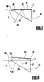
- the embodiment of the invention according to Fig 7 comprises a prism 7 which is a reflection prism according to Bauernfeind.
- a prism 7 produces a laterally proper beam deflection within a minimum of space. This is due to a utilization of the hypotenuse 30 of the prism partially as a transparent surface 36 for the passing beams and to the remaining part as a kind of mirror subjecting the light beam to total reflection.
- the way the light beams 31, 32, 33 are taking when passing through the prism 7 is indicated in Fig. 7 by arrows. It may be seen that the light beam 31 undergoes total reflection within the prism 7 at one part of the hypotenuse 30.
- the totally reflected light beam 32 impinges on cathetus 35 which is provided with a reflecting metal coating 21, for being reflected thereon as light beam 33 which emerges from the prism 7.
- input light beam 31 penetrates prism 7 transversely to the short cathetus 37, and outgoing light beam 31 leaves prism 7 transversely to the hypotenuse 30 at the other part 36 thereof.
- the reflective coating 21 is replaced by a flat mirror plate 24 mounted to a pivot 38.
- the angle ⁇ of the output light beam 33 with respect to the long cathetus 35 of prism 7 may vary whereas the input light beam 31 remains unchanged.
- the reflection of light beam 31 at the hypotenuse 30 can be improved by providing a metal coating 25 upon a portion of the hypotenuse 30 such that the emerging light beam 33 may leave the prism 7 unimpaired by the coating 25 through an uncoated portion 36 of the hypotenuse 30.
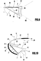
- the invention provides for a divergent lens 20 mounted ahead the short cathetus 37 of the prism 7 (Fig. 9).
- the bi-concave divergent lens 20 may have a focal distance between - 100 mm and - 130 mm or may have diopters between - 10 and - 8.
- the angle of the prism 7 may be selected to 60°.
- the incoming light 46 passes through the divergent lens 20 and enters the prism 7 vertically through the short cathetus 37, as thereafter totally reflected at the hypotenuse 30 within prism 7 optionally with the assistance of the coating 25, and is thereafter reflected at the metal coating 21 of the long cathetus 35 of prism 7.
- the reflected light emerges from the prism 7 through the transparent section 36 of hypotenuse 30.
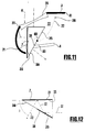
- Fig. 11 shows how the combination of the divergent lens 20 and prism 7 are built into the mirror housing 3 as a separate casing 28.
- Lens 20 is sealingly accommodated within an opening 6 in the forward outer end wall 41 of mirror housing 3, and prism 7 is mounted within the mirror housing behind the lens 20 such that the direction of the long cathetus 35 includes an angle with the (not shown) center line of lens 20.
- the casing 28 is formed with sealing walls 22 and 27 tightened to the wall of the mirror housing 3.
- Wall 22 of casing 28 is sealed at the hypotenuse 30, specifically at the metal coating 25 thereof, thereby forming a normally vertical line 60 of separation of the invisible part of the prism 7 from the transparent surface section 36 of the hypotenuse which forms the field of view 16 for the driver.
- the latter is provided with an outcut 50 which allows the prism 7 to extend partially rearwardly beyond rearview mirror element 4.
- the casing 28 forms a space 23 between the lens 20 and prism 7 from which humidity should be withdrawn in order to avoid condensation of water upon the optical surfaces of the lens 20 and prism 7.
- So casing 28 may be filled with dried air or any convenient protective case, e.g. SF 6 .
- Fig. 10 shows another embodiment of the invention according to which the divergent lens 20 and prism 7 are differently arranged within a separate casing 29.
- the casing 29 has a transparent portion 40 of wall section 41 of the mirror housing 3 through which light may penetrate casing 29 and impinge on divergent lens 20.
- Lens 20 is mounted aside the hypotenuse 30 close to the edge 43 formed by hypotenuse and long cathetus 35 of prism 7.
- the light impinging on lens 20 is indicated by arrow 45 and leaves the prism 7 through short cathetus 37 in a direction as indicated by arrow 47.
- the way of the light through prism 7 follows the opposite direction because it is first reflected by mirror coating 21 provided on the long cathetus 35 and is thereafter again reflected internally at a portion of the hypotenuse 30 not covered by lens 20.
- the last mentioned embodiment of the invention eases sealing of casing 29 at the prism 7 because wall 22 of casing 29 may be sealingly bond to edge 42 of prism 7 formed by hypotenuse 30 and short cathetus 37. Moreover, the last mentioned embodiment of the invention is advantageous therein that lens 20 is covered by the transparent section 40 and therefore the optical surfaces thereof are protected against dust and dirt. The field of view 16 for the driver is formed by the short cathetus 37.
- the driver When utilizing the mirror assembly according to the invention by the driver he will adjust the mirror housing such that he can best inspect the field of view. Such adjustment may be made by activating an electric motor which is commonly provided for electrically adjusting the position of the mirror housing with respect to the car body.
- an electric motor which is commonly provided for electrically adjusting the position of the mirror housing with respect to the car body.
- the horizontal viewing angle ⁇ and the vertical viewing angle ⁇ of the driver are selected according to the table given hereinafter.
- the driver should first assume a convenient sitting position behind the steering-wheel of the vehicle.
- the horizontal viewing angle ⁇ and the vertical viewing angle ⁇ are defined in Figs. 5 and 6 showing a driver 80 behind the steering-wheel 81 and directing his eyes towards the field of view 16 at the outer end of mirror housing 2.
- the horizontal viewing angle ⁇ is taken with respect to the direction of motion of the vehicle whereas the vertical viewing angle ⁇ is taken with respect to a horizontal plane.
- ⁇ ⁇ very small driver ca. 53° ca. 5° small driver ca. 48° ca. 5° normal driver ca. 42° ca. 14° tall driver ca. 39° ca. 14°
Landscapes
- Engineering & Computer Science (AREA)
- Multimedia (AREA)
- Mechanical Engineering (AREA)
- Rear-View Mirror Devices That Are Mounted On The Exterior Of The Vehicle (AREA)
- Lenses (AREA)
- Road Signs Or Road Markings (AREA)
Applications Claiming Priority (2)
| Application Number | Priority Date | Filing Date | Title |
|---|---|---|---|
| DE29621172U | 1996-12-06 | ||
| DE29621172U DE29621172U1 (de) | 1996-12-06 | 1996-12-06 | Außenspiegel mit Sehwinkelerweiterung |
Publications (2)
| Publication Number | Publication Date |
|---|---|
| EP0846597A2 true EP0846597A2 (de) | 1998-06-10 |
| EP0846597A3 EP0846597A3 (de) | 1999-01-20 |
Family
ID=8032906
Family Applications (1)
| Application Number | Title | Priority Date | Filing Date |
|---|---|---|---|
| EP97121456A Withdrawn EP0846597A3 (de) | 1996-12-06 | 1997-12-05 | Rückblickspiegel- Baugruppe für Kraftfahrzeuge |
Country Status (3)
| Country | Link |
|---|---|
| US (1) | US6104552A (de) |
| EP (1) | EP0846597A3 (de) |
| DE (1) | DE29621172U1 (de) |
Cited By (2)
| Publication number | Priority date | Publication date | Assignee | Title |
|---|---|---|---|---|
| WO2001002216A1 (fr) * | 1999-07-04 | 2001-01-11 | Abdelkader Behlouli | Biviseur automobiles |
| EP1106435A1 (de) * | 1999-12-02 | 2001-06-13 | Ford Global Technologies, Inc. | Bildaufnahme- und-wiedergabevorrichtung für Kraftfahrzeuge |
Families Citing this family (47)
| Publication number | Priority date | Publication date | Assignee | Title |
|---|---|---|---|---|
| US5910854A (en) | 1993-02-26 | 1999-06-08 | Donnelly Corporation | Electrochromic polymeric solid films, manufacturing electrochromic devices using such solid films, and processes for making such solid films and devices |
| US5668663A (en) | 1994-05-05 | 1997-09-16 | Donnelly Corporation | Electrochromic mirrors and devices |
| US6891563B2 (en) | 1996-05-22 | 2005-05-10 | Donnelly Corporation | Vehicular vision system |
| US6172613B1 (en) | 1998-02-18 | 2001-01-09 | Donnelly Corporation | Rearview mirror assembly incorporating vehicle information display |
| US6326613B1 (en) | 1998-01-07 | 2001-12-04 | Donnelly Corporation | Vehicle interior mirror assembly adapted for containing a rain sensor |
| US6124886A (en) | 1997-08-25 | 2000-09-26 | Donnelly Corporation | Modular rearview mirror assembly |
| US8294975B2 (en) | 1997-08-25 | 2012-10-23 | Donnelly Corporation | Automotive rearview mirror assembly |
| US6445287B1 (en) | 2000-02-28 | 2002-09-03 | Donnelly Corporation | Tire inflation assistance monitoring system |
| US8288711B2 (en) | 1998-01-07 | 2012-10-16 | Donnelly Corporation | Interior rearview mirror system with forwardly-viewing camera and a control |
| US6329925B1 (en) | 1999-11-24 | 2001-12-11 | Donnelly Corporation | Rearview mirror assembly with added feature modular display |
| US6693517B2 (en) | 2000-04-21 | 2004-02-17 | Donnelly Corporation | Vehicle mirror assembly communicating wirelessly with vehicle accessories and occupants |
| US6477464B2 (en) | 2000-03-09 | 2002-11-05 | Donnelly Corporation | Complete mirror-based global-positioning system (GPS) navigation solution |
| US7167796B2 (en) | 2000-03-09 | 2007-01-23 | Donnelly Corporation | Vehicle navigation system for use with a telematics system |
| US7370983B2 (en) | 2000-03-02 | 2008-05-13 | Donnelly Corporation | Interior mirror assembly with display |
| WO2001064481A2 (en) | 2000-03-02 | 2001-09-07 | Donnelly Corporation | Video mirror systems incorporating an accessory module |
| SE520042C2 (sv) * | 2000-10-26 | 2003-05-13 | Autoliv Dev | Anordning för förbättring av mörkersikten hos ett fordon såsom en bil |
| US20030202097A1 (en) * | 2000-10-26 | 2003-10-30 | Autoliv Development Ab | Night vision arrangement |
| US7255451B2 (en) | 2002-09-20 | 2007-08-14 | Donnelly Corporation | Electro-optic mirror cell |
| US7581859B2 (en) | 2005-09-14 | 2009-09-01 | Donnelly Corp. | Display device for exterior rearview mirror |
| WO2006124682A2 (en) | 2005-05-16 | 2006-11-23 | Donnelly Corporation | Vehicle mirror assembly with indicia at reflective element |
| EP1363810B1 (de) | 2001-01-23 | 2007-05-30 | Donnelly Corporation | Verbessertes fahrzeugbeleuchtungssystem |
| US7995095B2 (en) * | 2001-10-18 | 2011-08-09 | Autoliv Development Ab | Night vision device for a vehicle |
| US6918674B2 (en) | 2002-05-03 | 2005-07-19 | Donnelly Corporation | Vehicle rearview mirror system |
| EP1504276B1 (de) * | 2002-05-03 | 2012-08-08 | Donnelly Corporation | Objektdetektionssystem für ein fahrzeug |
| AU2003237424A1 (en) | 2002-06-06 | 2003-12-22 | Donnelly Corporation | Interior rearview mirror system with compass |
| US7329013B2 (en) | 2002-06-06 | 2008-02-12 | Donnelly Corporation | Interior rearview mirror system with compass |
| US7108384B1 (en) | 2002-07-16 | 2006-09-19 | Theophilos Athanassiou | Patrol vehicle safety mirror |
| EP1543358A2 (de) | 2002-09-20 | 2005-06-22 | Donnelly Corporation | Spiegelreflexionselementbaugruppe |
| US7310177B2 (en) | 2002-09-20 | 2007-12-18 | Donnelly Corporation | Electro-optic reflective element assembly |
| US7289037B2 (en) | 2003-05-19 | 2007-10-30 | Donnelly Corporation | Mirror assembly for vehicle |
| US7271823B2 (en) * | 2003-08-29 | 2007-09-18 | Ricoh Company, Ltd. | Optical scanner and image forming apparatus |
| US7446924B2 (en) | 2003-10-02 | 2008-11-04 | Donnelly Corporation | Mirror reflective element assembly including electronic component |
| US7308341B2 (en) | 2003-10-14 | 2007-12-11 | Donnelly Corporation | Vehicle communication system |
| US7720580B2 (en) | 2004-12-23 | 2010-05-18 | Donnelly Corporation | Object detection system for vehicle |
| JP4231484B2 (ja) * | 2005-01-25 | 2009-02-25 | 本田技研工業株式会社 | アウトサイドミラー装置 |
| EP1949666B1 (de) | 2005-11-01 | 2013-07-17 | Magna Mirrors of America, Inc. | Innen-rückspiegel mit display |
| US8154418B2 (en) | 2008-03-31 | 2012-04-10 | Magna Mirrors Of America, Inc. | Interior rearview mirror system |
| DE102008027307B4 (de) * | 2008-06-07 | 2017-07-06 | Leopold Kostal Gmbh & Co. Kg | Kameraanordnung für ein Kraftfahrzeug |
| US8331038B1 (en) * | 2008-09-30 | 2012-12-11 | Magna Mirrors Of America, Inc. | Vehicular rearview/sideview mirror assembly utilizing afocal optical assembly |
| US9487144B2 (en) | 2008-10-16 | 2016-11-08 | Magna Mirrors Of America, Inc. | Interior mirror assembly with display |
| EP2179892A1 (de) | 2008-10-24 | 2010-04-28 | Magna Electronics Europe GmbH & Co. KG | Verfahren zum automatischen Kalibrieren einer virtuellen Kamera |
| US8964032B2 (en) | 2009-01-30 | 2015-02-24 | Magna Electronics Inc. | Rear illumination system |
| EP2523831B2 (de) | 2010-01-13 | 2024-05-29 | Magna Electronics Inc. | Fahrzeugkamera und verfahren zur regelmässigen kalibrierung der fahrzeugkamera |
| US9358928B2 (en) | 2014-05-15 | 2016-06-07 | Kevin Anthony Smith | Forward and rearward viewing mirror device |
| GB201509697D0 (en) * | 2015-06-04 | 2015-07-22 | Boyle John | Vehicle mirror apparatus |
| US11228700B2 (en) | 2015-10-07 | 2022-01-18 | Magna Electronics Inc. | Vehicle vision system camera with adaptive field of view |
| US20190255997A1 (en) * | 2018-02-19 | 2019-08-22 | Gentex Corporation | Imaging device for rearview assembly |
Citations (1)
| Publication number | Priority date | Publication date | Assignee | Title |
|---|---|---|---|---|
| DE2918822A1 (de) | 1979-05-10 | 1980-11-20 | Hans Lang Kg Gmbh U Co Ing | Aussenspiegel fuer kraftfahrzeuge |
Family Cites Families (48)
| Publication number | Priority date | Publication date | Assignee | Title |
|---|---|---|---|---|
| FR743180A (de) * | 1933-03-25 | |||
| FR701260A (fr) * | 1930-08-28 | 1931-03-13 | Viseur latéral pour automobiles | |
| US1883296A (en) * | 1931-01-22 | 1932-10-18 | Corcoran Brown Lamp Company | Traffic observing instrument |
| US2622482A (en) * | 1950-01-19 | 1952-12-23 | Balkin Frank | Traffic viewing device |
| US2757575A (en) * | 1952-12-24 | 1956-08-07 | Frank G Kovach | Rear vision device |
| US2796003A (en) * | 1953-04-08 | 1957-06-18 | William J Kaufman | Periscopic device for automobiles |
| FR1398407A (fr) * | 1964-06-11 | 1965-05-07 | Pré-viseur de dépassement | |
| US3659929A (en) * | 1970-02-28 | 1972-05-02 | Masaharu Yuzawa | Back-mirror and side-mirror combination device |
| GB1422159A (en) * | 1972-04-06 | 1976-01-21 | Samuelson Film Service Ltd | Camera lens attachments marine propulsion apparatus |
| FR2182753A1 (de) * | 1972-05-05 | 1973-12-14 | Perrier Marcel | |
| US3809461A (en) * | 1972-05-12 | 1974-05-07 | Donnelly Mirrors Inc | View expanding and directing optical system |
| DE2352708A1 (de) * | 1973-10-20 | 1975-04-30 | Albert Grosskreutz | Optisches system an kraftfahrzeugen |
| DE2634372A1 (de) * | 1976-07-30 | 1978-02-02 | Shimizu | Kraftfahrzeug-rueckspiegel |
| SE7806265L (sv) * | 1977-06-02 | 1978-12-03 | Jitsumori Tsuneharu | Anordning vid en fordonsbackspegel |
| JPS5819942Y2 (ja) * | 1978-05-22 | 1983-04-25 | 日産自動車株式会社 | 自動車用アウトサイドミラ− |
| US5109214A (en) * | 1980-04-14 | 1992-04-28 | Heidman Jr William A | Vehicle directional signal switch with lane changing position interconnecting to flashing lamps on left and right side rear view mirrors and flashing brake lamps in reverse |
| US4475100A (en) * | 1982-02-22 | 1984-10-02 | Duh Ching Jeng | Side mirror with indicator light |
| US4646210A (en) * | 1984-06-20 | 1987-02-24 | Donnelly Corporation | Vehicular mirror and light assembly |
| JPS61188242A (ja) * | 1985-02-14 | 1986-08-21 | Nissan Shatai Co Ltd | ドアミラ− |
| JPS62218248A (ja) * | 1986-03-19 | 1987-09-25 | Okayama Hiroshi | 自動車用後退灯 |
| US4807096A (en) * | 1986-06-26 | 1989-02-21 | Donnelly Corporation | Interior light/carrier module for vehicles |
| US4733336A (en) * | 1986-06-26 | 1988-03-22 | Donnelly Corporation | Lighted/information case assembly for rearview mirrors |
| DE3635471A1 (de) * | 1986-10-18 | 1988-04-21 | Bayerische Motoren Werke Ag | Fahrzeugaussenspiegel mit leuchte |
| DE3635473A1 (de) * | 1986-10-18 | 1988-04-21 | Bayerische Motoren Werke Ag | Fahrzeugaussenspiegel mit einparkleuchte |
| IT211420Z2 (it) * | 1987-03-11 | 1989-03-06 | Miazzo Gianantonio | Specchietto retrovisore esterno per autoveicoli. |
| KR910002276B1 (ko) * | 1987-07-24 | 1991-04-11 | 기요시 야마다 | 차체 축방에 조명등을 설치한 백미러 |
| DE3807549A1 (de) * | 1988-03-08 | 1988-11-10 | Rolf Dipl Ing Eckert | Vorausblick-spiegelsystem fuer kfz zur vermeidung von auffahrunfaellen |
| US4916430A (en) * | 1988-11-03 | 1990-04-10 | Vu Thuan D | Back up rear view mirror light |
| US5594593A (en) * | 1988-12-17 | 1997-01-14 | Milner; Peter J. | Rear view system for a vehicle |
| FR2641243A1 (fr) * | 1989-01-03 | 1990-07-06 | Peugeot | Retroviseur exterieur d'un vehicule equipe d'un dispositif optique de depassement |
| US5017903C1 (en) * | 1989-02-21 | 2002-08-13 | Jacob Krippelz Sr | Emergency light |
| US4890907A (en) * | 1989-07-10 | 1990-01-02 | Vu Thuan D | Automatic mirror light |
| US5014167A (en) * | 1990-02-20 | 1991-05-07 | K. W. Muth Company, Inc. | Visual signaling apparatus |
| GB9107551D0 (en) * | 1991-04-10 | 1991-05-29 | Milner Peter J | A rear view mirror |
| FR2676030A1 (fr) * | 1991-05-02 | 1992-11-06 | Leghlid Mohamed | Viseur lateral avant pour une meilleure visibilite quand la visibilite du conducteur de voiture est masquee. |
| US5264962A (en) * | 1991-08-22 | 1993-11-23 | Kho Myung D | Sideview mirror for vehicles |
| US5178448A (en) * | 1991-09-13 | 1993-01-12 | Donnelly Corporation | Rearview mirror with lighting assembly |
| DE9201038U1 (de) * | 1992-01-29 | 1992-04-02 | Leube, Karl-Heinz, 5820 Gevelsberg | Fahrzeug |
| JPH05301539A (ja) * | 1992-04-28 | 1993-11-16 | Tokai Rika Co Ltd | 自動車の補助ミラー |
| US5313335A (en) * | 1992-06-05 | 1994-05-17 | Delco Electronics Corporation | Blindzone signal indicator |
| US5497306A (en) * | 1993-02-01 | 1996-03-05 | Donnelly Corporation | Exterior vehicle security light |
| US5371659A (en) * | 1993-02-01 | 1994-12-06 | Donnelly Corporation | Remote-actuated exterior vehicle security light |
| ES1028292Y (es) * | 1994-06-13 | 1995-05-16 | Ibanez Juan Vicente Marcos | Espejo retrovisor perfeccionado. |
| US5594594A (en) * | 1994-08-05 | 1997-01-14 | Ung; Ly W. | Non-distorted blind spot mirror using a triangular prism for all types of vehicles |
| US5669699A (en) * | 1994-11-02 | 1997-09-23 | Donnelly Corporation | Exterior vehicle security light |
| DE29508198U1 (de) * | 1995-05-11 | 1995-07-20 | Schuster, Jürgen, 88368 Bergatreute | Optische/optoelektronische Überholhilfe für Kraftfahrzeuge |
| US5669698A (en) * | 1995-05-24 | 1997-09-23 | Veldman; Roger L. | Modular rearview mirror assembly and method for making same |
| US5624176A (en) * | 1995-10-25 | 1997-04-29 | Donnelly Corporation | Illuminated power tilt exterior mirror for vehicle |
-
1996
- 1996-12-06 DE DE29621172U patent/DE29621172U1/de not_active Expired - Lifetime
-
1997
- 1997-12-05 US US08/985,928 patent/US6104552A/en not_active Expired - Fee Related
- 1997-12-05 EP EP97121456A patent/EP0846597A3/de not_active Withdrawn
Patent Citations (1)
| Publication number | Priority date | Publication date | Assignee | Title |
|---|---|---|---|---|
| DE2918822A1 (de) | 1979-05-10 | 1980-11-20 | Hans Lang Kg Gmbh U Co Ing | Aussenspiegel fuer kraftfahrzeuge |
Cited By (2)
| Publication number | Priority date | Publication date | Assignee | Title |
|---|---|---|---|---|
| WO2001002216A1 (fr) * | 1999-07-04 | 2001-01-11 | Abdelkader Behlouli | Biviseur automobiles |
| EP1106435A1 (de) * | 1999-12-02 | 2001-06-13 | Ford Global Technologies, Inc. | Bildaufnahme- und-wiedergabevorrichtung für Kraftfahrzeuge |
Also Published As
| Publication number | Publication date |
|---|---|
| US6104552A (en) | 2000-08-15 |
| DE29621172U1 (de) | 1998-04-09 |
| EP0846597A3 (de) | 1999-01-20 |
Similar Documents
| Publication | Publication Date | Title |
|---|---|---|
| US6104552A (en) | Vehicular rearview mirror assembly with forward vision optical system | |
| EP0758834B1 (de) | Kostengünstiges Nachsichtgerät für Fahrzeuge und Verfahren zur Montage | |
| US4892386A (en) | On-vehicle head up display device with double images angularly separated less than a monocular resolving power | |
| US5619370A (en) | Optical system for viewing a remote location | |
| US4968124A (en) | Vehicle viewing system | |
| US6717610B1 (en) | Wide angle image capture system for vehicle | |
| US3809462A (en) | View expanding and directing optical system | |
| US6757085B1 (en) | Image representation system and method for vehicles | |
| US3909117A (en) | Vehicular rear viewing device | |
| GB2263453A (en) | Rear view systems | |
| US4187001A (en) | View expanding apparatus | |
| US3394978A (en) | Dual side split rearview reflecting system | |
| US5221990A (en) | Wide field of view automotive rear vision optical system | |
| US3704062A (en) | Rear view optical system | |
| EP0961714B1 (de) | Optisches rückblicksystem | |
| US3001450A (en) | Rear vision optical system | |
| JP3305417B2 (ja) | 車両左右方向死角モニター | |
| US3915561A (en) | Periscopic viewing system | |
| EP1569819B1 (de) | Fahrzeugspiegelsystem | |
| US3001449A (en) | Optical system | |
| US3372970A (en) | Traffic light indicator | |
| JPH0664472A (ja) | 車両用端部位置表示装置 | |
| RU2140861C1 (ru) | Устройство переднего обзора автомобиля с нестандартным расположением руля | |
| GB2261861A (en) | Driving mirror | |
| RU2302350C2 (ru) | Устройство переднего обзора для автомобилей с правым расположением руля |
Legal Events
| Date | Code | Title | Description |
|---|---|---|---|
| PUAI | Public reference made under article 153(3) epc to a published international application that has entered the european phase |
Free format text: ORIGINAL CODE: 0009012 |
|
| AK | Designated contracting states |
Kind code of ref document: A2 Designated state(s): AT BE CH DE DK ES FI FR GB GR IE IT LI LU MC NL PT SE |
|
| AX | Request for extension of the european patent |
Free format text: AL;LT;LV;MK;RO;SI |
|
| PUAL | Search report despatched |
Free format text: ORIGINAL CODE: 0009013 |
|
| AK | Designated contracting states |
Kind code of ref document: A3 Designated state(s): AT BE CH DE DK ES FI FR GB GR IE IT LI LU MC NL PT SE |
|
| AX | Request for extension of the european patent |
Free format text: AL;LT;LV;MK;RO;SI |
|
| AKX | Designation fees paid | ||
| STAA | Information on the status of an ep patent application or granted ep patent |
Free format text: STATUS: THE APPLICATION IS DEEMED TO BE WITHDRAWN |
|
| 18D | Application deemed to be withdrawn |
Effective date: 19990721 |