EP0846868A2 - Unité de soufflante centrifugale - Google Patents
Unité de soufflante centrifugale Download PDFInfo
- Publication number
- EP0846868A2 EP0846868A2 EP97203477A EP97203477A EP0846868A2 EP 0846868 A2 EP0846868 A2 EP 0846868A2 EP 97203477 A EP97203477 A EP 97203477A EP 97203477 A EP97203477 A EP 97203477A EP 0846868 A2 EP0846868 A2 EP 0846868A2
- Authority
- EP
- European Patent Office
- Prior art keywords
- axially
- housing
- end wall
- blower
- circular edge
- Prior art date
- Legal status (The legal status is an assumption and is not a legal conclusion. Google has not performed a legal analysis and makes no representation as to the accuracy of the status listed.)
- Withdrawn
Links
Images


Classifications
-
- F—MECHANICAL ENGINEERING; LIGHTING; HEATING; WEAPONS; BLASTING
- F04—POSITIVE - DISPLACEMENT MACHINES FOR LIQUIDS; PUMPS FOR LIQUIDS OR ELASTIC FLUIDS
- F04D—NON-POSITIVE-DISPLACEMENT PUMPS
- F04D17/00—Radial-flow pumps, e.g. centrifugal pumps; Helico-centrifugal pumps
- F04D17/06—Helico-centrifugal pumps
-
- F—MECHANICAL ENGINEERING; LIGHTING; HEATING; WEAPONS; BLASTING
- F04—POSITIVE - DISPLACEMENT MACHINES FOR LIQUIDS; PUMPS FOR LIQUIDS OR ELASTIC FLUIDS
- F04D—NON-POSITIVE-DISPLACEMENT PUMPS
- F04D29/00—Details, component parts, or accessories
- F04D29/26—Rotors specially for elastic fluids
- F04D29/28—Rotors specially for elastic fluids for centrifugal or helico-centrifugal pumps for radial-flow or helico-centrifugal pumps
- F04D29/281—Rotors specially for elastic fluids for centrifugal or helico-centrifugal pumps for radial-flow or helico-centrifugal pumps for fans or blowers
- F04D29/282—Rotors specially for elastic fluids for centrifugal or helico-centrifugal pumps for radial-flow or helico-centrifugal pumps for fans or blowers the leading edge of each vane being substantially parallel to the rotation axis
-
- F—MECHANICAL ENGINEERING; LIGHTING; HEATING; WEAPONS; BLASTING
- F04—POSITIVE - DISPLACEMENT MACHINES FOR LIQUIDS; PUMPS FOR LIQUIDS OR ELASTIC FLUIDS
- F04D—NON-POSITIVE-DISPLACEMENT PUMPS
- F04D29/00—Details, component parts, or accessories
- F04D29/40—Casings; Connections of working fluid
- F04D29/42—Casings; Connections of working fluid for radial or helico-centrifugal pumps
- F04D29/4206—Casings; Connections of working fluid for radial or helico-centrifugal pumps especially adapted for elastic fluid pumps
- F04D29/4226—Fan casings
- F04D29/4233—Fan casings with volutes extending mainly in axial or radially inward direction
Definitions
- This invention relates to centrifugal blower assemblies of the type used in automotive applications.
- Centrifugal blowers have been used extensively in automotive heating and air conditioning systems for some time.
- a centrifugal blower consists of a series of radially disposed, axially extending blades that are rotated about a central motor drive shaft axis.
- the blower sits within and is surrounded by a so called volute housing.
- the blades force air radially outwardly, thereby pulling outside air in one axial direction down the center of the blower through an air entrance into the housing, or sometimes through in both directions through two air entrances.
- the drawn-in air is forced radially outwardly and is captured between four walls of the volute housing that surround the blower and define a spiral air flow space.
- These four walls typically include a cylindrical inner wall and a radially opposed outer wall that spirals around the inner wall, moving progressively radially farther away therefrom in the direction of blower rotation.
- the inner and outer walls are typically bounded by two substantially flat axially opposed end (or side) walls, which are generally axially spaced apart by the same amount at every point. Air leaving the blower enters the spiral air space through a cylindrical inlet opening cut through the inner wall, usually subtending a full 360 degrees.
- the spiral air space also has a tangential outlet formed by the terminal edges of the four housing walls, and the outlet is generally axially aligned with the housing inlet opening. Air passing through the inlet swirls around in the direction of blower rotation, finally exiting the tangential outlet.
- the blower is mounted within and surrounded by the housing inner wall, so that the blower blades are axially aligned with the housing inlet opening.
- air exiting the blower blades has a radially outward velocity, but no deliberate or distinct axial velocity component in either axial direction.
- the air entering the volute housing can rebound axially from the end walls, causing vortices which, while they are damped out and indistinguishable by the time the tangential outlet is reached, tend to decrease efficiency.
- volute housing has the two axially opposed end walls moving progressively apart, as the radially opposed peripheral walls do, in the direction of blower rotation. Examples may be seen in USPN 3,246,834 issued April 19, 1966 to Swenson (end walls 8, referred to as “side walls”) and USPN 3,407,995 issued October 29, 1968 to Kinsworthy (end walls 35, also referred to as "side” walls). Volutes with both radial and axial expansion have been known for several decades, and rather complex formulae have been proposed for governing the degree of end wall axial expansion. This type of housing has proved particularly useful with a centrifugal blower of the type having rearwardly inclined blades.
- the blower though not well illustrated, apparently still sits within the inner peripheral wall of the volute housing, presumably axially aligned with the volute housing inlet opening cut through the volute's inner peripheral wall (which is also not well illustrated).
- the 5,156,524 patent proposes an extremely complex formula for the volute shape, supposedly to improve the air flow efficiency, but does not describe specifically the axial asymmetry that the housing inlet opening (and blower, presumably) has relative to the tangential outlet, nor any negative effect on air flow due to that asymmetry.
- Patents describing various designs for the volute housing often say little about the design of the centrifugal blower itself, although it is sometimes indicated whether the blades are forwardly or rearwardly inclined (sometimes referred to as forwardly or rearwardly curved.) Some patents describe very specific angles for the lead and trailing edges of the blower blades. However, less attention is typically paid to the rest of the blower, that is, to the structural elements that actually physically support the blades in the blower. Still, a pattern is evident across the various patents that describe different volute housing designs, and which also show some detail for the blower.
- the blades In a typical centrifugal blower, the blades, whether forwardly or rearwardly curved, are radially disposed, like spokes of a wheel, and are axially captured between an upper tip ring and a lower base rim.
- the tip ring is basically an annulus, although it may be concave, like a section of a bowl.
- the base rim is also basically an annulus, and while it may be integral to a bowl shaped central dome, it is generally flat itself.
- the dome is designed to clear the upper end of the motor that spins the drive shaft, and the drive shaft is fixed to the center of the dome.
- the blower is located well down inside the blower housing, and does not extend very far, if at all, above the upper end wall of the housing. Consequently, the housing air entrance, which is just above the inner edge of the blower tip ring, also does not extend very far above the upper end wall of the housing.
- the blower is generally substantially axially aligned with the cylindrical housing inlet opening. That is, the outer circular edges of the blower tip ring and base rim are both concentric to, and near, the respective upper and lower edges of the housing inlet opening. Being flat, the entire base rim is axially aligned with the lower axial edge of the housing inlet opening.
- air pumped radially outwardly and out through the housing inlet opening by such a blower has no defined axial component.
- a centrifugal blower assembly in accordance with the present invention is characterised by the features specified in claim 1.
- the blower assembly includes a volute housing that has several structural features common to a typical axially expanding, but axially asymmetrical volute housing of the typed described above. That is, it has a flat upper end wall and a lower end wall that spirals steeply axially away from the upper end wall.
- the housing inlet is axially displaced above the tangential outlet, with an upper circular edge that is near the flat upper end wall, and a lower circular edge that sits axially well above the lower end wall.
- the circular air entrance to the housing is displaced axially well above the flat upper end wall and above the upper edge of the housing inlet opening, rather than being nearly flush to the flat upper end wall. More generally stated, the circular air entrance is displaced relative to the cylindrical housing inlet opening in the axial direction opposite to the direction in which the lower end wall is displaced relative to the housing inlet opening.
- the centrifugal blower assembly also has a centrifugal blower with some structural features common to a typical centrifugal blower. It has radially disposed blades held between a generally annular tip ring and base rim, which is integral to a bowl shaped central dome. However, the tip ring curves radially outwardly and axially downwardly more steeply than is conventional. The base rim, rather than being flat, curves in the same direction as the tip ring, though not as steeply.
- the inner circular edge of the tip ring is located concentric to and near the circular air entrance of the housing and, therefore, axially well above the upper edge of the housing air inlet.
- the tip ring slopes steeply down to an outer edge located concentric and near to the inlet opening upper edge.
- the base rim since it is not flat, is not completely axially aligned with the lower edge of the housing inlet opening. Instead, the base rim begins at an inner circular edge that is between the two edges of the housing inlet opening, and slopes axially downwardly and radially outwardly to an outer circular edge, which is concentric to and axially aligned with the lower edge of the housing inlet opening.
- the base rim is not sloped as steeply as the tip ring, the general trend of the cylindrical space between the tip ring and base rim ( as measured moving progressively radially outwardly) is a gradual decrease in height coupled with a gradual axial downward shift of the space per se, that is, down toward the lower edge of the inlet opening.
- the unique shape of the space between the more highly sloped tip ring and the curved base rim, and the axially upward shifting (relative to the housing inlet) of both the upper edge of the blower and the housing air entrance creates a different air flow.
- the air that is drawn in through the entrance by the rotating blower and sent radially outwardly through the blades and into the cylindrical housing inlet is given a significant axially downward component of velocity, by virtue of being simultaneously forced axially downwardly between the tip ring and base rim, as it passes radially through the blades.
- the air is forced axially downwardly and toward the axially displaced housing end wall, and flows through the entire spiral air space of the volute housing more efficiently.
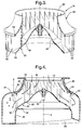
- a centrifugal blower assembly has a preferred embodiment of which is indicated generally at 10, has two main components, and a volute housing, indicated generally at 12, and a centrifugal blower, indicated generally at 14, both of which are made up of molded plastic parts.
- Blower 14 is rotated counterclockwise, by a motor drive shaft 16, about a central axis indicated at A.
- Shaft 16 is part of a conventional electric motor 18.
- volute housing 12 is the axially expanding, but axially asymmetrical type. As such, a spiral air space is formed around the central axis A, defined by four walls.
- R1 through R3 are progressively greater, and are determined according to conventional and well established formulae.
- the other two walls defining the spiral air space are a first, upper end wall 24, which is flat, and a second, spiraling lower end wall 26.
- Upper and lower are understood to be terms of convenient reference related to the orientation of the drawing on the page, and are not intended to be limiting as to the orientation of the blower assembly 10 per se.
- the two end walls 24 and 26 move axially progressively away from one another, moving in the direction of rotation.
- Outlet 34 is axially displaced downwardly relative to the inlet opening 28, since the terminal edge of the spiraling end wall 26 is axially spaced away from the flat upper end wall 24 to the greatest degree, Z3, at the outlet 34.
- This axial displacement of the outlet away from inlet is typical of axially expanding volute housings with one fiat end wall.
- the outside air entrance to the housing 12 (not to be confused with the housing inlet opening 28 to the spiral air flow space) is defined by a circular lip 36, in conjunction with a coaming 38. Lip 36 sits atop coaming 38, axially well above the flat upper end wall 24, by a distance indicated at H, rather than being almost flush therewith.
- Lip 36 is riveted separately to coaming 38, which surrounds the inlet upper edge 30 and is molded integrally to the upper end wall 24.
- blower 14 has radially disposed, axially extending blades 40, which may be, as illustrated, rearwardly inclined (rearwardly curved).
- An axially expanding volute housing like 12 is particularly suited for that type of blower, although the invention is not so limited.
- the blades 40 are held and confined axially between a lower base rim, indicated generally at 42, and an upper tip ring, indicated generally at 44.
- the lower ends of the blades 40 are a molded integral extension of the base rim 42, while tip ring 44 is added to the upper ends of the blades by sonic welding, adhesive, riveting, or any desired fastening process.
- Base rim 42 may itself be, as in the embodiment disclosed, an integrally molded extension from the outer edge of a semi spherical dome 46.
- a dome like 46 is a convenient means for joining the entire blower 14 to shaft 16.
- base rim 42 could be a visually distinct part, rotatably fixed to shaft 16 by some other means, or, dome 46 could be relieved by openings large enough to reduce it to little more than a series of spokes.
- base rim 42 may be conceptualized as having an inner circular edge 48 and an outer circular edge 50.
- a conventional base rim would be flat, with axially aligned inner and outer edges, as indicated by the dotted line in Figure 2.
- base rim 42 slopes axially downwardly and radially outwardly from inner edge 48 to outer edge 50.
- Tip ring 44 has a shape generally like conventional tip rings, which curve radially outwardly and axially downwardly, from an inner circular edge 52 to an outer circular edge 54. The basic purpose for this is to create an air flow area between the tip ring 44 and base rim 42 that is progressively axially shorter as it grows in radius, so as to hold a substantially constant flow volume.
- blower 14 is fixed to shaft 16, and the lip 36 is riveted to the flat upper edge of coaming 38. This orients the tip ring inner edge 52 near, and basically concentric to the lip 36.
- the shape of the coaming 38 closely matches and is slightly spaced from the blower tip ring 44, so as to present the smallest possible pressurized air leak path.
- the lip 36 also axially overlaps the tip ring inner edge 52 slightly, to further block any air leakage.
- blower 14 The two outer circular edges of blower 14, the tip ring outer edge 54 and base rim outer edge 50, are both located proximate to and substantially concentric to the respective upper 30 and lower 32 edges of the housing inlet opening 28. Since the base rim 42 is curved, however, its inner edge 48 is not axially aligned with the housing inlet lower edge 32, as would be the case with a conventional flat base rim. Instead, it is intermediate the inlet's two edges 30 and 32, although closer to the lower edge 32. This orientation of the various edges of blower 14 relative to the lip 36 and the housing inlet edges 30 and 32 creates a unique air flow pattern, indicated by the arrows in Figure 4.
- the air flow carries, at this point, a substantial axial velocity component in addition to the radial. This is indicated by the dotted lines R and Z, which represent a resolution of the air flow into radial and axial components respectively.
- the air flow is actually three dimensional, of course, and is also concurrently spiraling counterclockwise around the axis A. However, its axial velocity component is the feature most relevant to the invention. Because of that axial velocity component, the spiraling air flow will tend to flow around and down, approaching and conforming to the axially displaced lower end wall 26 more closely than it otherwise would. The air flow will also be less likely to rebound axially downwardly from the upper end wall 24, with the resultant flow vortices and reduction in flow efficiency.
- the flow exiting the axially displaced tangential outlet 34 will also be more regular and efficient, and its axial profile will be more uniform and even. It bears repeating, at this point, that "upper” and “lower” are arbitrary directions.
- the second, non flattened end wall 26 is axially displaced in one direction, be that up, down or right, left. Therefore, the tangential housing outlet 34 is displaced relative to the cylindrical inlet opening 28 in the same direction.
- the fresh air entrance provided by the lip 36 is axially displaced relative to the flattened end wall 24 in the opposite axial direction. And the air flow is given a significant axial component in the direction of axial displacement, so as to mitigate the flow inefficiencies that would otherwise result from that axial displacement and asymmetry.
- blower hub configured as a semi spherical dome 46 is not new per se, and its particular shape has historically been seen simply as a necessity to clear the end of the motor 18.
- a dome shaped hub has been continuous, in every design, but is often relieved with very large openings in order to pass cooling air to the motor.
- the blower hub has been flat or nearly so, nearly coplanar with the flat base rim.
- the base rim has been nearly flat, since there was apparently no perceived reason for it to be anything but flat.
- the curved shape of the dome 46 almost blends into the curvature of the base rim 42.
- the dome 46 in fact cooperates with and assists the axially opposed base rim 42 and tip ring 44 in imparting the desired axial velocity component to the air flow.
- any such axial component imparted to the air flow by the dome 46 was essentially lost when the air hit the flat base rim 42 and was turned back into a radially outward flow.
- the basic shape of the tip ring 44 and base rim 42 would work if the base rim 42 were integral to a basically flat hub, such as would exist with a motor that did not intrude axially as far upwardly as motor 18. Therefore, it will be understood that it is not intended to limit the invention to just the embodiment disclosed.
Landscapes
- Engineering & Computer Science (AREA)
- Mechanical Engineering (AREA)
- General Engineering & Computer Science (AREA)
- Structures Of Non-Positive Displacement Pumps (AREA)
- Air-Conditioning For Vehicles (AREA)
Applications Claiming Priority (2)
| Application Number | Priority Date | Filing Date | Title |
|---|---|---|---|
| US76077196A | 1996-12-05 | 1996-12-05 | |
| US760771 | 1996-12-05 |
Publications (2)
| Publication Number | Publication Date |
|---|---|
| EP0846868A2 true EP0846868A2 (fr) | 1998-06-10 |
| EP0846868A3 EP0846868A3 (fr) | 1999-02-03 |
Family
ID=25060143
Family Applications (1)
| Application Number | Title | Priority Date | Filing Date |
|---|---|---|---|
| EP97203477A Withdrawn EP0846868A3 (fr) | 1996-12-05 | 1997-11-10 | Unité de soufflante centrifugale |
Country Status (2)
| Country | Link |
|---|---|
| EP (1) | EP0846868A3 (fr) |
| JP (1) | JPH10176696A (fr) |
Cited By (31)
| Publication number | Priority date | Publication date | Assignee | Title |
|---|---|---|---|---|
| FR2789447A1 (fr) | 1999-02-10 | 2000-08-11 | Valeo Climatisation | Dispositif de chauffage et/ou climatisation comprenant un pulseur centrifuge |
| WO2000059358A1 (fr) * | 1999-04-06 | 2000-10-12 | Oreck Holdings, Llc | Soufflante pour aspirateur à écoulement équilibré |
| FR2801941A1 (fr) * | 1999-12-06 | 2001-06-08 | Valeo Climatisation | Installation de chauffage-climatisation comprenant au moins un pulseur centrifuge |
| EP1210264A4 (fr) * | 1999-07-16 | 2002-12-04 | Bosch Robert Corp | Turbine centrifuge a courbure de pale elevee |
| CN1096574C (zh) * | 1998-07-28 | 2002-12-18 | 三洋电机株式会社 | 电动鼓风机 |
| EP1178215A3 (fr) * | 2000-08-04 | 2003-04-09 | Calsonic Kansei Corporation | Soufflante centrifugal |
| FR2868813A1 (fr) * | 2004-04-09 | 2005-10-14 | Valeo Climatisation Sa | Organe de propulsion centrifuge d'air pour installation de chauffage, de ventilation et/ou de climatisation d'un habitacle de vehicule notamment |
| EP1582750A3 (fr) * | 2004-03-22 | 2005-12-21 | Behr GmbH & Co. KG | Boitier, roue et soufflante avec un boitier et une roue |
| US7481617B2 (en) | 2004-05-19 | 2009-01-27 | Delta Electronics, Inc. | Heat-dissipating device |
| WO2012130437A1 (fr) * | 2011-03-28 | 2012-10-04 | Berling Gmbh | Hotte aspirante à mélange d'air amélioré |
| DE102005027460B4 (de) * | 2004-06-18 | 2013-07-11 | Delta Electronics, Inc. | Wärme ableitende Vorrichtung |
| DE102005026423B4 (de) * | 2004-06-18 | 2013-08-08 | Delta Electronics, Inc. | Wärme ableitende Vorrichtung |
| CN104454633A (zh) * | 2013-09-13 | 2015-03-25 | 博西华电器(江苏)有限公司 | 吸油烟机及其风机系统 |
| EP2886874A1 (fr) * | 2013-12-20 | 2015-06-24 | ebm-papst Mulfingen GmbH & Co. KG | Roue radiale pour un ventilateur à tambour et ventilateur doté d'une telle roue radiale |
| CN105065332A (zh) * | 2015-09-11 | 2015-11-18 | 珠海格力电器股份有限公司 | 一种空调、鼓形蜗壳风道系统及其风道蜗壳 |
| WO2016016614A1 (fr) * | 2014-07-29 | 2016-02-04 | Dyson Technology Limited | Ensemble ventilateur |
| US9568017B2 (en) | 2014-04-30 | 2017-02-14 | Denso International America, Inc. | Quieter centrifugal blower with suppressed BPF tone |
| CN106715922A (zh) * | 2014-10-14 | 2017-05-24 | 松下知识产权经营株式会社 | 离心式鼓风机及具备该离心式鼓风机的汽车 |
| US9752789B2 (en) | 2012-03-06 | 2017-09-05 | Dyson Technology Limited | Humidifying apparatus |
| US9797612B2 (en) | 2013-01-29 | 2017-10-24 | Dyson Technology Limited | Fan assembly |
| US9797613B2 (en) | 2012-03-06 | 2017-10-24 | Dyson Technology Limited | Humidifying apparatus |
| US9903602B2 (en) | 2014-07-29 | 2018-02-27 | Dyson Technology Limited | Humidifying apparatus |
| US9927136B2 (en) | 2012-03-06 | 2018-03-27 | Dyson Technology Limited | Fan assembly |
| US9982677B2 (en) | 2014-07-29 | 2018-05-29 | Dyson Technology Limited | Fan assembly |
| US9989066B2 (en) | 2013-03-14 | 2018-06-05 | Mahle International Gmbh | Low power and low noise fan-scroll with multiple split incoming air-streams |
| CN108386371A (zh) * | 2018-05-11 | 2018-08-10 | 浙江爱尔菲集成家居有限公司 | 一种带螺旋风道的多功能厨房吹风扇 |
| US10408478B2 (en) | 2012-03-06 | 2019-09-10 | Dyson Technology Limited | Humidifying apparatus |
| CN110259724A (zh) * | 2019-05-30 | 2019-09-20 | 宁波方太厨具有限公司 | 一种用于离心风机的蜗壳及应用有该蜗壳的离心风机 |
| US10465928B2 (en) | 2012-03-06 | 2019-11-05 | Dyson Technology Limited | Humidifying apparatus |
| US10612565B2 (en) | 2013-01-29 | 2020-04-07 | Dyson Technology Limited | Fan assembly |
| CN115163560A (zh) * | 2022-07-08 | 2022-10-11 | 约克广州空调冷冻设备有限公司 | 蜗壳及包括其的离心风机 |
Families Citing this family (4)
| Publication number | Priority date | Publication date | Assignee | Title |
|---|---|---|---|---|
| KR100461647B1 (ko) * | 2002-05-08 | 2004-12-14 | 엘지전자 주식회사 | 공기조화기용 터보팬 |
| GB2518638B (en) | 2013-09-26 | 2016-10-12 | Dyson Technology Ltd | Humidifying apparatus |
| GB2528709B (en) | 2014-07-29 | 2017-02-08 | Dyson Technology Ltd | Humidifying apparatus |
| US12595807B2 (en) | 2024-09-24 | 2026-04-07 | Hanon Systems | Dome blower wheel attachment to minimize water intrusion |
Family Cites Families (5)
| Publication number | Priority date | Publication date | Assignee | Title |
|---|---|---|---|---|
| US3584968A (en) * | 1969-10-06 | 1971-06-15 | Howard I Furst | Fan construction |
| US3829250A (en) * | 1971-09-22 | 1974-08-13 | Torin Corp | Blower assembly |
| US4890598A (en) * | 1988-07-29 | 1990-01-02 | Nu-Tech Industries, Inc. | High efficiency blower |
| DE4006373A1 (de) * | 1990-03-01 | 1991-09-05 | Opel Adam Ag | Gehaeuse fuer ein geblaese einer kraftfahrzeugheizung oder klimaanlage |
| DE9116263U1 (de) * | 1991-12-17 | 1992-07-23 | Kohl, Hans, 5275 Bergneustadt | Gebläse zum Fördern gasförmiger Medien |
-
1997
- 1997-11-10 EP EP97203477A patent/EP0846868A3/fr not_active Withdrawn
- 1997-12-05 JP JP33555297A patent/JPH10176696A/ja active Pending
Cited By (38)
| Publication number | Priority date | Publication date | Assignee | Title |
|---|---|---|---|---|
| CN1096574C (zh) * | 1998-07-28 | 2002-12-18 | 三洋电机株式会社 | 电动鼓风机 |
| FR2789447A1 (fr) | 1999-02-10 | 2000-08-11 | Valeo Climatisation | Dispositif de chauffage et/ou climatisation comprenant un pulseur centrifuge |
| WO2000059358A1 (fr) * | 1999-04-06 | 2000-10-12 | Oreck Holdings, Llc | Soufflante pour aspirateur à écoulement équilibré |
| US6348106B1 (en) | 1999-04-06 | 2002-02-19 | Oreck Holdings, Llc | Apparatus and method for moving a flow of air and particulate through a vacuum cleaner |
| EP1210264A4 (fr) * | 1999-07-16 | 2002-12-04 | Bosch Robert Corp | Turbine centrifuge a courbure de pale elevee |
| EP1106837A1 (fr) * | 1999-12-06 | 2001-06-13 | Valeo Climatisation | Boítier d'un ventilateur |
| FR2801941A1 (fr) * | 1999-12-06 | 2001-06-08 | Valeo Climatisation | Installation de chauffage-climatisation comprenant au moins un pulseur centrifuge |
| EP1178215A3 (fr) * | 2000-08-04 | 2003-04-09 | Calsonic Kansei Corporation | Soufflante centrifugal |
| US6604906B2 (en) | 2000-08-04 | 2003-08-12 | Calsonic Kansei Corporation | Centrifugal multiblade blower |
| EP1582750A3 (fr) * | 2004-03-22 | 2005-12-21 | Behr GmbH & Co. KG | Boitier, roue et soufflante avec un boitier et une roue |
| FR2868813A1 (fr) * | 2004-04-09 | 2005-10-14 | Valeo Climatisation Sa | Organe de propulsion centrifuge d'air pour installation de chauffage, de ventilation et/ou de climatisation d'un habitacle de vehicule notamment |
| US7481617B2 (en) | 2004-05-19 | 2009-01-27 | Delta Electronics, Inc. | Heat-dissipating device |
| DE102005027460B4 (de) * | 2004-06-18 | 2013-07-11 | Delta Electronics, Inc. | Wärme ableitende Vorrichtung |
| DE102005026423B4 (de) * | 2004-06-18 | 2013-08-08 | Delta Electronics, Inc. | Wärme ableitende Vorrichtung |
| WO2012130437A1 (fr) * | 2011-03-28 | 2012-10-04 | Berling Gmbh | Hotte aspirante à mélange d'air amélioré |
| US9927136B2 (en) | 2012-03-06 | 2018-03-27 | Dyson Technology Limited | Fan assembly |
| US9797613B2 (en) | 2012-03-06 | 2017-10-24 | Dyson Technology Limited | Humidifying apparatus |
| US10465928B2 (en) | 2012-03-06 | 2019-11-05 | Dyson Technology Limited | Humidifying apparatus |
| US10408478B2 (en) | 2012-03-06 | 2019-09-10 | Dyson Technology Limited | Humidifying apparatus |
| US10563875B2 (en) | 2012-03-06 | 2020-02-18 | Dyson Technology Limited | Humidifying apparatus |
| US9752789B2 (en) | 2012-03-06 | 2017-09-05 | Dyson Technology Limited | Humidifying apparatus |
| US9797612B2 (en) | 2013-01-29 | 2017-10-24 | Dyson Technology Limited | Fan assembly |
| US10612565B2 (en) | 2013-01-29 | 2020-04-07 | Dyson Technology Limited | Fan assembly |
| US9989066B2 (en) | 2013-03-14 | 2018-06-05 | Mahle International Gmbh | Low power and low noise fan-scroll with multiple split incoming air-streams |
| CN104454633A (zh) * | 2013-09-13 | 2015-03-25 | 博西华电器(江苏)有限公司 | 吸油烟机及其风机系统 |
| EP2886874A1 (fr) * | 2013-12-20 | 2015-06-24 | ebm-papst Mulfingen GmbH & Co. KG | Roue radiale pour un ventilateur à tambour et ventilateur doté d'une telle roue radiale |
| US9568017B2 (en) | 2014-04-30 | 2017-02-14 | Denso International America, Inc. | Quieter centrifugal blower with suppressed BPF tone |
| CN105317661A (zh) * | 2014-07-29 | 2016-02-10 | 戴森技术有限公司 | 风扇组件 |
| WO2016016614A1 (fr) * | 2014-07-29 | 2016-02-04 | Dyson Technology Limited | Ensemble ventilateur |
| US9903602B2 (en) | 2014-07-29 | 2018-02-27 | Dyson Technology Limited | Humidifying apparatus |
| US9982677B2 (en) | 2014-07-29 | 2018-05-29 | Dyson Technology Limited | Fan assembly |
| CN106715922A (zh) * | 2014-10-14 | 2017-05-24 | 松下知识产权经营株式会社 | 离心式鼓风机及具备该离心式鼓风机的汽车 |
| CN106715922B (zh) * | 2014-10-14 | 2018-12-28 | 松下知识产权经营株式会社 | 离心式鼓风机及具备该离心式鼓风机的汽车 |
| EP3208472A4 (fr) * | 2014-10-14 | 2017-10-04 | Panasonic Intellectual Property Management Co., Ltd. | Soufflante centrifuge et automobile la comportant |
| CN105065332A (zh) * | 2015-09-11 | 2015-11-18 | 珠海格力电器股份有限公司 | 一种空调、鼓形蜗壳风道系统及其风道蜗壳 |
| CN108386371A (zh) * | 2018-05-11 | 2018-08-10 | 浙江爱尔菲集成家居有限公司 | 一种带螺旋风道的多功能厨房吹风扇 |
| CN110259724A (zh) * | 2019-05-30 | 2019-09-20 | 宁波方太厨具有限公司 | 一种用于离心风机的蜗壳及应用有该蜗壳的离心风机 |
| CN115163560A (zh) * | 2022-07-08 | 2022-10-11 | 约克广州空调冷冻设备有限公司 | 蜗壳及包括其的离心风机 |
Also Published As
| Publication number | Publication date |
|---|---|
| JPH10176696A (ja) | 1998-06-30 |
| EP0846868A3 (fr) | 1999-02-03 |
Similar Documents
| Publication | Publication Date | Title |
|---|---|---|
| EP0846868A2 (fr) | Unité de soufflante centrifugale | |
| US7172387B2 (en) | Fan guard for blower unit | |
| KR100818429B1 (ko) | 고효율의 단일형 원심형 블로워 | |
| US9086073B2 (en) | Blower assembly | |
| JP5645596B2 (ja) | 多翼遠心ファンおよびそれを用いた空気調和機 | |
| US7500825B2 (en) | Centrifugal blower | |
| US9157449B2 (en) | Multi-blade centrifugal fan and air conditioner using the same | |
| EP1923572B1 (fr) | Ventilateur électrique pour nettoyeur électrique | |
| EP2275689A1 (fr) | Ventilateur centrifuge | |
| EP0490308B1 (fr) | Virole en forme d'orifice pour ventilateur axial | |
| US7207779B2 (en) | Impeller for radial-flow heat dissipating fan | |
| US11732730B2 (en) | Blower assembly | |
| US6217285B1 (en) | Impeller for a centrifugal blower | |
| US7125226B2 (en) | Impeller for radial-flow heat dissipating fan | |
| US20210262488A1 (en) | Ventilator and deflector plate for a ventilator | |
| WO2007085798A1 (fr) | Turbine et ventilateur ameliores | |
| US20080187439A1 (en) | Blower assembly with pre-swirler | |
| WO2006006668A1 (fr) | Ventilateur centrifuge et climatiseur équipé d'un ventilateur centrifuge | |
| US5120193A (en) | Baffle for reducing airflow noise in a scroll housing | |
| JP5151331B2 (ja) | 多翼羽根車および多翼送風機 | |
| JP3120411B2 (ja) | 多翼送風機 | |
| JP2004218450A (ja) | 遠心式送風機 | |
| JP2715839B2 (ja) | 遠心式送風機 | |
| KR20020087235A (ko) | 다익송풍기 | |
| JP3438269B2 (ja) | 多翼送風機 |
Legal Events
| Date | Code | Title | Description |
|---|---|---|---|
| PUAI | Public reference made under article 153(3) epc to a published international application that has entered the european phase |
Free format text: ORIGINAL CODE: 0009012 |
|
| AK | Designated contracting states |
Kind code of ref document: A2 Designated state(s): AT BE CH DE DK ES FI FR GB GR IE IT LI LU MC NL PT SE |
|
| AX | Request for extension of the european patent |
Free format text: AL;LT;LV;MK;RO;SI |
|
| PUAL | Search report despatched |
Free format text: ORIGINAL CODE: 0009013 |
|
| AK | Designated contracting states |
Kind code of ref document: A3 Designated state(s): AT BE CH DE DK ES FI FR GB GR IE IT LI LU MC NL PT SE |
|
| AX | Request for extension of the european patent |
Free format text: AL;LT;LV;MK;RO;SI |
|
| AKX | Designation fees paid | ||
| STAA | Information on the status of an ep patent application or granted ep patent |
Free format text: STATUS: THE APPLICATION IS DEEMED TO BE WITHDRAWN |
|
| 18D | Application deemed to be withdrawn |
Effective date: 19990804 |
|
| REG | Reference to a national code |
Ref country code: DE Ref legal event code: 8566 |