EP0846940B1 - Methode und Vorrichtung zur Temperaturkompensation in einer Kraftmesszelle eines Lastdetektors - Google Patents
Methode und Vorrichtung zur Temperaturkompensation in einer Kraftmesszelle eines Lastdetektors Download PDFInfo
- Publication number
- EP0846940B1 EP0846940B1 EP97309496A EP97309496A EP0846940B1 EP 0846940 B1 EP0846940 B1 EP 0846940B1 EP 97309496 A EP97309496 A EP 97309496A EP 97309496 A EP97309496 A EP 97309496A EP 0846940 B1 EP0846940 B1 EP 0846940B1
- Authority
- EP
- European Patent Office
- Prior art keywords
- temperature
- load cell
- cell type
- load
- thermal source
- Prior art date
- Legal status (The legal status is an assumption and is not a legal conclusion. Google has not performed a legal analysis and makes no representation as to the accuracy of the status listed.)
- Expired - Lifetime
Links
Images


Classifications
-
- G—PHYSICS
- G01—MEASURING; TESTING
- G01G—WEIGHING
- G01G3/00—Weighing apparatus characterised by the use of elastically-deformable members, e.g. spring balances
- G01G3/18—Temperature-compensating arrangements
-
- G—PHYSICS
- G01—MEASURING; TESTING
- G01L—MEASURING FORCE, STRESS, TORQUE, WORK, MECHANICAL POWER, MECHANICAL EFFICIENCY, OR FLUID PRESSURE
- G01L1/00—Measuring force or stress, in general
- G01L1/20—Measuring force or stress, in general by measuring variations in ohmic resistance of solid materials or of electrically-conductive fluids; by making use of electrokinetic cells, i.e. liquid-containing cells wherein an electrical potential is produced or varied upon the application of stress
- G01L1/22—Measuring force or stress, in general by measuring variations in ohmic resistance of solid materials or of electrically-conductive fluids; by making use of electrokinetic cells, i.e. liquid-containing cells wherein an electrical potential is produced or varied upon the application of stress using resistance strain gauges
- G01L1/2268—Arrangements for correcting or for compensating unwanted effects
- G01L1/2281—Arrangements for correcting or for compensating unwanted effects for temperature variations
Definitions
- the present invention relates to a load detecting apparatus using a load cell type load detector (hereinafter simply referred to as "load cell”), and more particularly to a load detecting apparatus using a load cell in which the temperature compensation is effected for variations of a zero point of the load cell caused by temperature changes.
- load cell load cell type load detector
- the method with which the measured value is compensated by taking the temperature changes into consideration has a problem in that the method is very complicated. Also, the method in which the influence from temperature changes is attempted to be reduced by adding such an element as a temperature compensation element to a circuit such as a bridge circuit has a problem in that, when there is a large extent of temperature changes, the temperature compensation of the measured values to within a limited value not only involves technical difficulties but also complicates the circuit concerned, thus increasing the cost involved.
- the Japanese Patent Application Kokai Publication No. Sho 54-55474 discloses a technique which, with a comparatively simple arrangement and with an object of ensuring to overcome the influence of temperature changes, attempts to maintain a constant temperature of a load cell by providing heat sources and heat sensitive elements in the neighborhood of the periphery of a case of the load cell and controlling temperatures of the heat sources by the heat sensitive elements.
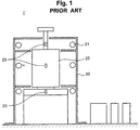
- the load cell 22 supported on the mounting base is covered by a cover 20 and there are provided a plurality of air conditioning means 21 for adjusting the temperature in the spaces formed by the cover 20 and a plurality of temperature measuring elements 23 for measuring the temperatures of the load cell 22, the mounting base, etc.
- This technique disclosed in the Japanese Patent Application Kokai Publication No. Hei 1-152317 attempts to realize a load detecting apparatus with which errors caused by a temperature drift is reduced by controlling the air conditioning means 21 such that the respective temperatures measured by the temperature measuring elements 23 become constant.
- This technique is to prevent the changes in the voltages outputted from the load cell which occur when the temperatures of the load cell are changed in the state wherein the constant load is being applied.
- the arrangement disclosed in the Japanese Patent Application Kokai Publication No. Hei 1-152317 attempts to prevent the temperature drift by maintaining a constant temperature higher than environment temperature changes in order to eliminate the influence of such environment temperature changes.
- An object of the invention is to overcome the problems existing in the prior art, and to provide a method and apparatus for effecting temperature compensation in a load cell formed with a strain gauge attached to a deflectable body or a sensing element.
- a method for effecting temperature compensation in a load cell type load detector formed with a strain gauge attached to a deflectable body comprising the steps of:
- an apparatus for effecting temperature compensation in a load cell type load detector in a load detecting apparatus having a mount base, a deflectable body provided on the mount base, a strain gauge attached to the deflectable body, and a load generating section for receiving a flow of objects to be measured, the apparatus for effecting temperature compensation comprising:
- the deflectable body is heated or cooled by both the symmetrically positioned thermal source blocks so that, because of the internal thermal conduction within the deflectable body, the temperature of the overall load cell, particularly that of the deflectable body having the strain gauge at its center portion, can always be controlled to a constant temperature. Also, by providing the thermal source blocks respectively between load generating portions such as between the deflectable body and a load cell mounting portion and between the deflectable body and a hopper, the thermal conduction (heat radiation) from the deflectable body is only to the ambient air so that no unbalanced heat radiation develops.
- thermal source blocks provided in the symmetric positions and the heat radiation of the heat to the ambient air between the thermal source blocks, it is made possible to control the temperature of the overall load cell to a constant temperature and to provide an apparatus which is easy to handle and low cost.
- Each of the embodiments covers a load cell of a type in which a deflectable body (sensing element) utilizing a Roberval mechanism is used and to which a strain gauge is attached.
- Fig. 2 shows a load cell type load detecting apparatus 1 of a first embodiment of the invention.
- the load cell 2 has a bottom portion fixed to a mount base 3 with a thermally conductive member 4 being interposed therebetween.
- a load detecting plate 6 which is a load generating portion is fixed over the load cell 2 with a thermally conductive member 5 of substantially equal mass as the thermally conductive member 4 being interposed therebetween.
- the thermally conductive members 4, 5 are fixed respectively at two symmetric positions of the load cell 2, and the thermally conductive members 4, 5 are respectively fixed to the mount base 3 and the load detecting plate 6.
- the embodiment illustrated covers the main portion of an arrangement of a flow meter in which the objects being measured flow on an inclined surface 7 of the load detecting plate 6, the load on the inclined surface is detected by the load cell 2, and the load is converted to a flow rate of the objects.
- the thermally conductive members 4, 5 are respectively provided with heaters 8, 9 as thermal elements and temperature sensors 10, 11.
- the heaters 8, 9 and the temperature sensors 10, 11 are connected to a temperature setting and controlling means 12.
- the temperature setting and controlling means 12 compares the values (temperature) detected by the temperature sensors 10, 11 with the target values (temperature) set in advance, and, for example, the electric current to be supplied to the heaters 8, 9 is controlled so as to eliminate a difference between the temperature values.
- any heaters as long as they efficiently heat the thermally conductive members 4, 5 are acceptable so that any heaters best suited and available at the time when the invention is put into practice may be selected.
- the temperature sensors 10, 11, the most commonly used ones are thermistors, but the use is not limited to the thermistors as long as they are capable of outputting signals as the measured values of the temperatures and are preferably compact. Or, they may be detecting elements that are attached to the deflectable body.
- the thermally conductive members 4, 5 should preferably have a large thermal capacity though being compact, and preferably they are capable of heating the load cell 2 with the heat from the heaters 8, 9 being retained for a long period of time.
- the thermally conductive members 4, 5 have functions as thermal sources. If the thermally conductive members 4, 5 are such that they suit to the thermal sources and have strength to endure the load, they may be metal, or may be of a material such as ceramic.
- Fig. 3 shows in detail an apparatus for temperature compensation in a load cell 2, the apparatus consisting of a deflectable body 13 and a strain gauge 14.
- the strain gauge 14 attached to the deflectable body 13 being approximately at the center (to be more precise, the center being a center portion of the hollow portion of the load cell)
- a thermal source block 15 consisting of a thermally conductive member 4 and a heater 8
- a thermal source block 16 consisting of a thermally conductive member 5 and a heater 9 are provided at symmetric positions of the deflectable body 13.
- the deflectable body 13 is heated from both the thermal source blocks 15, 16 disposed at the symmetric positions and, because of the thermal conduction within the deflectable body 13, the temperature of the overall load cell 2, particularly the deflectable body 13 having the strain gauge 14 substantially at its center, can always be maintained at a constant temperature. Further, since it has been so arranged that there is no heat conduction by the thermal source blocks 15, 16 from the deflectable body to any portions other than the deflectable body 13, that is, to portions such as the mount base 3 and the load detecting plate 6, so that the thermal conduction (heat radiation) is restricted only to the ambient air.
- This embodiment of the invention is directed to an example wherein, as shown in Fig. 2, a single point load cell is used, and the hollow portion at a center portion of the load cell is constricted.
- a single point load cell is used, and the hollow portion at a center portion of the load cell is constricted.
- the temperature of the deflectable body at the side where the thermal source block exists becomes high while, with the constricted portion as a dividing boundary, the temperature at the side where the thermal source block is not present becomes low.
- the provision of such a thermal source block causes the internal temperature of the deflectable body to be unbalanced. This is the most inappropriate state in conditions for using the load cell. Therefore, it is important that, for achieving the balanced temperatures within the deflectable body, the thermally conductive members of substantially equal masses be provided respectively to the two end portions of the load cell and be used as the thermal sources.
- the range of the compensation environment temperatures of an ordinary single point load cell is from -10°C to 40°C and the estimated range of temperatures used in the load cell is from 0°C to 35°C.
- the temperature control may be by way of only cooling.
- a heater may be used while, as the cooling means, a Peltier element may be used. In this way, the apparatus does not require a large installation as required in the prior art, and the desired temperature compensation can be carried out at low cost.
- Fig. 4 shows an apparatus for effecting temperature compensation in the load cell as a second embodiment of the invention.
- the difference from the first embodiment is that thermal insulating members 17, 18 are used.
- the arrangements are the same as those in the first embodiment so that the same explanation is not repeated here.
- the thermal insulating members 17, 18 are interposed respectively between the thermal source block 15 and the mount base 3 and between the thermal source block 16 and the load detecting plate 6.
- the thermal insulating members 17, 18 are provided, the heat generated by the thermal source blocks 15, 16 is not conducted to the mount base 3 and the load detecting plate 6, and the thermal source blocks 15, 16 are ensured to heat only the load cell 2 and the heat loss is reduced. As a result, it is possible to make a rapid temperature control of the load cell and to enhance the precision of the temperature control.
- Fig. 5 shows an example of most simple configuration of a temperature setting and controlling means which is used in the temperature compensation apparatus according to the invention and in which a bimetal switch is used.
- the bimetal switch 19 is provided within the thermally conductive members 5(4) and is connected in series with a heater 9(8) as a heating means and a power source 30.
- the bimetal switch 19 in which the operation temperature is 40°C is used, when the temperature of the thermal source block 16(15) reaches 40°C, the bimetal switch 19 turns OFF, and the heating by the heater 9(8) is stopped. Then, as the temperature of the heat source is lowered, the bimetal switch 19 turns ON, and the heater 9 begins to heat the thermally conductive member 5(4) again.
- the temperature control is made by a repeated intermittent supply of the electric current to the heater 9(8), but since the thermally conductive members 4, 5 themselves are masses having a large thermal capacity, no problem is presented in the maintenance of a constant temperature of the load cell 2 to be heated. Although it depends on the necessity of the measuring precision and the magnitude of changes in the environment temperatures of the environments in which the control is made, the above explained simple temperature controlling means can be practically used and the cost can be considerably reduced.
- the temperature controlling means of this type besides the bimetal switch, it is possible to utilize an arrangement in which a control means is incorporated in a thermo-sensitive device itself. Also, such means may be an advanced temperature controlling means utilizing a means such as a controller.
- the thermal source blocks 15, 16 are not limited to those which heat the load cell since those which cool the same can also be used.
- Peltier elements 51, 52 which are thermal elements for cooling are provided instead of the heaters 8, 9 which are thermal elements for heating.
- the Peltier elements 51, 52 on the surface of the thermally conductive members 4, 5 and controlling a cooling temperature of the load cell to a temperature below a range of operating temperatures but below a lower limit of compensating environment temperatures, for example, a temperature in the neighborhood of -10°C, it is possible to eliminate the influence of environment temperature changes to the load cell 2 as in the case where the load cell is heated.
- a cooling temperature of the load cell to a temperature below a range of operating temperatures but below a lower limit of compensating environment temperatures, for example, a temperature in the neighborhood of -10°C.
- the load cell itself may be that of a conventionally available general type so that the invention can be put in practice at a low cost.
- the load cell is in contact only with the thermal source blocks and, since the load cell is separated from other parts such as the mount base and the load detecting plate, the load cell can come in contact only with the ambient air, and this ensures that there is no unbalanced radiation of heat from the deflectable body. There; fore, it is easy to make the temperature control of the load cell.
- thermal insulating members are provided respectively between one of the thermal source blocks and the fixing member (mounting base) and between the other of the thermal source blocks and the load detecting plate, it is ensured that the thermal source blocks heat only the load cell, resulting in reducing any heat losses and in facilitating the temperature control of the load cell.
Landscapes
- Physics & Mathematics (AREA)
- General Physics & Mathematics (AREA)
- Measurement Of Force In General (AREA)
- Investigating Strength Of Materials By Application Of Mechanical Stress (AREA)
Claims (10)
- Verfahren zum Bewirken einer Temperaturkompensation in einem Kraftmeßzellentyp-Lastdetektor (2), welcher mit einem an einem durchbiegbaren Körper (13) festgelegten Dehnungsmeßstreifen (14) ausgebildet ist, wobei das Verfahren dadurch gekennzeichent ist, daß es die Schritte umfaßt:Vorsehen eines Paares von thermisch leitfähigen Wärmequellenblöcken (15, 16), um direkt in Kontakt mit dem durchbiegbaren Körper zu gelangen und entsprechend an zwei symmetrischen Positionen relativ zu einem Zentrum des durchbiegbaren Körpers angeordnet zu werden; undTemperatursteuerung bzw. -regelung einer Temperatur des durchbiegbaren Körpers (13) durch die Wärmequellenblöcke (15, 16), sodaß die Temperatur des Kraftmeßzellentyp-Lastdetektors (2) nicht durch Umgebungstemperaturänderungen beeinflußt wird und auf einer konstanten Temperatur gehalten wird.
- verfahren zum Bewirken einer Temperaturkompensation mit einem Kraftmeßzellentyp-Lastdetektor nach Anspruch 1, in welchem der Schritt der Temperatursteuerung bzw. -regelung durch einen Umschaltvorgang von Bimetallschaltern (19) durchgeführt wird, welche innerhalb der Wärmequellenblöcke (15, 16) vorgesehen sind.
- Verfahren zum Bewirken einer Temperaturkompensation mit einem Kraftmeßzellentyp-Lastdetektor nach Anspruch 1, in welchem der Schritt der Temperatursteuerung bzw. -regelung derart durchgeführt wird, daß die Temperatur des Kraftmeßzellentyp-Lastdetektors (2) so gesteuert bzw. geregelt wird, daß sie über einer Raumtemperatur, jedoch unter einer oberen Grenze einer kompensierenden Umgebungstemperatur des Kraftmeßzellentyp-Lastdetektors liegt.
- Verfahren zum Bewirken einer Temperaturkompensation mit einem Kraftmeßzellentyp-Lastdetektor nach Anspruch 1, in welchem der Schritt der Temperatursteuerung bzw. -regelung derart durchgeführt wird, daß die Temperatur des Kraftmeßzellentyp-Lastdetektors (2) so gesteuert bzw. geregelt wird, daß sie unter einer Raumtemperatur, jedoch über einer unteren Grenze einer kompensierenden Umgebungstemperatur des Kraftmeßzellentyp-Lastdetektors liegt.
- Vorrichtung zum Bewirken einer Temperaturkompensation in einem Kraftmeßzellentyp-Lastdetektor (2) in einer Lastdetektionsvorrichtung (1) mit einer Montagebasis (3), einem auf der Montagebasis (3) vorgesehenen, durchbiegbaren Körper (13), einem an dem durchbiegbaren Körper festgelegten Dehnungsmeßstreifen (14) und einem eine Last bzw. Belastung erzeugenden Abschnitt (6) zur Aufnahme eines Stroms von zu messenden Objekten, wobei die Vorrichtung zum Bewirken der Temperaturkompensation dadurch gekennzeichnet ist, daß sie umfaßt:ein Paar von thermisch leitfähigen Wärmequellenblöcken (15, 16), welche angeordnet sind, daß sie direkt in Kontakt mit dem durchbiegbaren Körper (13) stehen, wobei die Wärmequellenblöcke (15, 16) entsprechend an zwei symmetrischen Positionen relativ zu einem zentrum des durchbiegbaren Körpers (13) angeordnet sind und thermische Elemente (8, 9; 51, 52) in oder an den Wärmequellenblöcken aufweisen; undein Paar von Temperatursensoren (10, 11; 19), welche entsprechend an den Wärmequellenblöcken (15, 16) vorgesehen sind;eine Steuer- bzw. Regeleinrichtung (12; 19) zur Steuerung bzw. Regelung der thermischen Elemente (8, 9; 51, 52) basierend auf durch die Temperatursensoren (10, 11) detektierten Temperaturen, sodaß eine Temperatur des Kraftmeßzellentyp-Lastdetektors (2) bei einer vorbestimmten, konstanten Temperatur aufrechterhalten werden kann.
- vorrichtung zum Bewirken einer Temperaturkompensation in einem Kraftmeßzellentyp-Lastdetektor nach Anspruch 5, wobei einer (15) der Wärmequellenblöcke zwischen der Montagebasis (3) und dem Kraftmeßzellentyp-Lastdetektor (2) vorgesehen ist und der andere (16) der Wärmequellenblöcke zwischen dem die Last erzeugenden Abschnitt (6) und dem Kraftmeßzellentyp-Lastdetektor (2) vorgesehen ist.
- Vorrichtung zum Bewirken einer Temperaturkompensation in einem Kraftmeßzellentyp-Lastdetektor nach Anspruch 5, worin die thermischen Elemente Heizeinrichtungen (8, 9) zum Anheben einer Temperatur des Kraftmeßzellentyp-Lastdetektors umfassen, sodaß diese über einer Raumtemperatur, jedoch unter einer oberen Grenze einer kompensierenden Umgebungstemperatur des Kraftmeßzellentyp-Lastdetektors liegt.
- Vorrichtung zum Bewirken einer Temperaturkompensation in einem Kraftmeßzellentyp-Lastdetektor nach Anspruch 5, worin die thermischen Elemente Peltier-Elemente (51, 52) zum Absenken einer Temperatur des Kraftmeßzellentyp-Lastdetektors umfassen, sodaß diese unter einer Raumtemperatur, jedoch über einer unteren Grenze einer kompensierenden Umgebungstemperatur des Kraftmeßzellentyp-Lastdetektors liegt.
- Vorrichtung zum Bewirken einer Temperaturkompensation in einem Kraftmeßzellentyp-Lastdetektor nach Anspruch 5, worin die Steuer- bzw. Regeleinrichtung für die Temperatursensoren Bimetallschalter (19) umfaßt.
- vorrichtung zum Bewirken einer Temperaturkompensation in einem Kraftmeßzellentyp-Lastdetektor nach Anspruch 5, worin zwischen einem (15) der Wärmequellenblöcke und der Montagebasis und zwischen dem anderen (16) der Wärmequellenblöcke und dem die Last erzeugenden Abschnitt (6) jeweils thermische Isolierglieder (17, 18) vorgesehen sind.
Applications Claiming Priority (4)
| Application Number | Priority Date | Filing Date | Title |
|---|---|---|---|
| JP342654/96 | 1996-12-05 | ||
| JP34265496 | 1996-12-05 | ||
| JP309581/97 | 1997-10-24 | ||
| JP9309581A JPH10221183A (ja) | 1996-12-05 | 1997-10-24 | ロードセル荷重検出器の温度補償方法及びその装置 |
Publications (2)
| Publication Number | Publication Date |
|---|---|
| EP0846940A1 EP0846940A1 (de) | 1998-06-10 |
| EP0846940B1 true EP0846940B1 (de) | 1999-05-12 |
Family
ID=26566005
Family Applications (1)
| Application Number | Title | Priority Date | Filing Date |
|---|---|---|---|
| EP97309496A Expired - Lifetime EP0846940B1 (de) | 1996-12-05 | 1997-11-25 | Methode und Vorrichtung zur Temperaturkompensation in einer Kraftmesszelle eines Lastdetektors |
Country Status (11)
| Country | Link |
|---|---|
| US (1) | US6173619B1 (de) |
| EP (1) | EP0846940B1 (de) |
| JP (1) | JPH10221183A (de) |
| KR (1) | KR100308439B1 (de) |
| CN (1) | CN1190737A (de) |
| AU (1) | AU717357B2 (de) |
| CA (1) | CA2221659A1 (de) |
| DE (1) | DE69700218T2 (de) |
| ES (1) | ES2131424T3 (de) |
| MY (1) | MY116174A (de) |
| TW (1) | TW350909B (de) |
Cited By (1)
| Publication number | Priority date | Publication date | Assignee | Title |
|---|---|---|---|---|
| DE10359866A1 (de) * | 2003-12-18 | 2005-07-21 | Endress + Hauser Gmbh + Co. Kg | Vorrichtung und Verfahren zur Kompensation von Drucksensoren |
Families Citing this family (25)
| Publication number | Priority date | Publication date | Assignee | Title |
|---|---|---|---|---|
| DE10131062C1 (de) * | 2001-06-27 | 2002-12-05 | Sartorius Gmbh | Wägeaufnehmer mit Parallelführung und Ecklasteinstellung |
| CN1853111B (zh) * | 2003-08-18 | 2010-04-28 | 株式会社爱德万测试 | 温度控制装置和方法、电子部件试验装置和方法及处理机 |
| DE102004054644A1 (de) * | 2004-11-11 | 2006-05-18 | Endress + Hauser Gmbh + Co. Kg | Vorrichtung und Verfahren zum Kompensieren von Messwertaufnehmern |
| JP2007021836A (ja) * | 2005-07-14 | 2007-02-01 | Toyo Mach & Metal Co Ltd | 射出成形機 |
| US7361852B2 (en) * | 2006-07-07 | 2008-04-22 | Mettler-Toledo Ag | Weighing module |
| US7371978B2 (en) * | 2006-07-07 | 2008-05-13 | Mettler-Toledo Ag | Thermally insulated weighing module |
| EP1925922A1 (de) | 2006-11-24 | 2008-05-28 | Mettler-Toledo AG | Temperierbare Mehrfachwägevorrichtung |
| EP1947432A3 (de) * | 2007-01-19 | 2011-03-16 | Fraunhofer-Gesellschaft zur Förderung der angewandten Forschung e.V. | Temperatursensor, Sensor und Verfahren zum bestimmen einer Temperatur eines Mediums, Verfahren zum Herstellen eines Temperatursensors zur verbesserten Bestimmung einer Temperatur eines Mediums und Verfahren zum Herstellen eines Sensors, der zusätzlich eine Temperatur eines Mediums bestimmen kann |
| US7647837B2 (en) * | 2007-08-29 | 2010-01-19 | Honeywell International Inc. | Active temperature differential compensation for strain gage based sensors |
| JP5207997B2 (ja) * | 2009-01-22 | 2013-06-12 | 大和製衡株式会社 | ロードセル |
| US8191434B2 (en) * | 2009-04-03 | 2012-06-05 | Mettler-Toledo, LLC | Device and method for temperature compensation testing of digital load cells |
| KR101107110B1 (ko) * | 2009-10-23 | 2012-01-31 | 한국전력공사 | 하중 측정 장치 |
| EP3163269B1 (de) * | 2015-10-29 | 2019-05-08 | Mettler-Toledo GmbH | Waage mit aktiver wärmeflusssteuerung |
| CN106595917A (zh) * | 2017-02-03 | 2017-04-26 | 山东省计量科学研究院 | 一种大力值数字式力传感器 |
| CN110546474B (zh) * | 2017-04-25 | 2022-01-21 | 奥腾工业自动化(廊坊)有限公司 | 一种用于力/扭矩传感器温度补偿的方法 |
| CN108332837A (zh) * | 2017-12-06 | 2018-07-27 | 芯海科技(深圳)股份有限公司 | 一种应用于电子秤的基于bp神经网络补偿温度增益方法 |
| TWI721460B (zh) * | 2018-07-13 | 2021-03-11 | 美商愛康運動與健康公司 | 自行車鞋功率感測器 |
| JP7400211B2 (ja) * | 2019-05-16 | 2023-12-19 | セイコーエプソン株式会社 | ロボットシステム、制御装置およびロボットの制御方法 |
| US11402257B1 (en) * | 2019-11-21 | 2022-08-02 | Amazon Technologies, Inc. | System for compensation of weight sensor |
| JP7441493B2 (ja) * | 2020-03-19 | 2024-03-01 | 株式会社イシダ | ロードセルユニット及び計量装置 |
| CN112097915B (zh) * | 2020-09-10 | 2022-07-26 | 江西省桑格尔电子有限公司 | 一种人脸识别测温方法及装置 |
| CN113566940A (zh) * | 2021-08-27 | 2021-10-29 | 东莞市速力科技有限公司 | 一种石英称重传感器 |
| CN115824574A (zh) * | 2023-02-09 | 2023-03-21 | 中国航空工业集团公司沈阳空气动力研究所 | 一种具备温度自调节功能的天平装置及安装与调节方法 |
| KR102914622B1 (ko) * | 2023-06-26 | 2026-01-22 | 주식회사 바우테크 | 피더 장치 |
| CN119290221B (zh) * | 2024-10-11 | 2025-11-11 | 广东海洋大学 | 一种基于irime-cnn-dd的硅压阻式压力传感器温度补偿方法及系统 |
Family Cites Families (13)
| Publication number | Priority date | Publication date | Assignee | Title |
|---|---|---|---|---|
| JPS5455474A (en) | 1977-10-12 | 1979-05-02 | Teraoka Seikosho Kk | Temperature compensation load meter |
| US4198868A (en) * | 1979-02-12 | 1980-04-22 | Rockwell International Corporation | Strain gauge apparatus and means for treating temperature dependency |
| US4365520A (en) * | 1981-01-07 | 1982-12-28 | Gould Inc. | Strain gage transducers |
| GB8314846D0 (en) * | 1983-05-27 | 1983-07-06 | Bell & Howell Co | Temperature controlled electronic devices |
| JPH01152317A (ja) * | 1987-12-10 | 1989-06-14 | Nishishiba Electric Co Ltd | 荷重検出装置 |
| JPH01318932A (ja) * | 1988-06-21 | 1989-12-25 | Hitachi Constr Mach Co Ltd | 荷重検出器 |
| US5929390A (en) * | 1994-09-14 | 1999-07-27 | Ishida Co., Ltd. | Load cell weighing apparatus using the same |
| US5922998A (en) * | 1994-12-27 | 1999-07-13 | Zefira; Uri | Built-in weighing scale |
| DE19501231C2 (de) * | 1995-01-17 | 1998-01-29 | Inter Control Koehler Hermann | Thermisch betätigbare Vorrichtung mit Bimetall-Element |
| US5850057A (en) * | 1996-09-04 | 1998-12-15 | The University Of Akron | Electromagnetically controlled load cell |
| US5869788A (en) * | 1997-05-30 | 1999-02-09 | Circuits And Systems, Inc. | Weighing scale with EMI/RFI shielding |
| US5894112A (en) * | 1997-06-26 | 1999-04-13 | Intercomp Company | Weighing scale apparatus |
| US5950573A (en) * | 1998-10-16 | 1999-09-14 | Srp 687 Pty. Ltd. | Power vented water heater with air inlet |
-
1997
- 1997-10-24 JP JP9309581A patent/JPH10221183A/ja active Pending
- 1997-11-20 CA CA002221659A patent/CA2221659A1/en not_active Abandoned
- 1997-11-20 TW TW086117379A patent/TW350909B/zh active
- 1997-11-22 MY MYPI97005623A patent/MY116174A/en unknown
- 1997-11-25 EP EP97309496A patent/EP0846940B1/de not_active Expired - Lifetime
- 1997-11-25 ES ES97309496T patent/ES2131424T3/es not_active Expired - Lifetime
- 1997-11-25 DE DE69700218T patent/DE69700218T2/de not_active Expired - Fee Related
- 1997-11-26 AU AU45418/97A patent/AU717357B2/en not_active Ceased
- 1997-12-02 US US08/982,376 patent/US6173619B1/en not_active Expired - Fee Related
- 1997-12-04 KR KR1019970065928A patent/KR100308439B1/ko not_active Expired - Fee Related
- 1997-12-05 CN CN97119899A patent/CN1190737A/zh active Pending
Cited By (1)
| Publication number | Priority date | Publication date | Assignee | Title |
|---|---|---|---|---|
| DE10359866A1 (de) * | 2003-12-18 | 2005-07-21 | Endress + Hauser Gmbh + Co. Kg | Vorrichtung und Verfahren zur Kompensation von Drucksensoren |
Also Published As
| Publication number | Publication date |
|---|---|
| CN1190737A (zh) | 1998-08-19 |
| TW350909B (en) | 1999-01-21 |
| JPH10221183A (ja) | 1998-08-21 |
| US6173619B1 (en) | 2001-01-16 |
| KR100308439B1 (ko) | 2002-01-17 |
| AU717357B2 (en) | 2000-03-23 |
| EP0846940A1 (de) | 1998-06-10 |
| ES2131424T3 (es) | 1999-07-16 |
| DE69700218T2 (de) | 1999-11-04 |
| AU4541897A (en) | 1998-06-11 |
| CA2221659A1 (en) | 1998-06-05 |
| KR19980063796A (ko) | 1998-10-07 |
| MY116174A (en) | 2003-11-28 |
| DE69700218D1 (de) | 1999-06-17 |
Similar Documents
| Publication | Publication Date | Title |
|---|---|---|
| EP0846940B1 (de) | Methode und Vorrichtung zur Temperaturkompensation in einer Kraftmesszelle eines Lastdetektors | |
| US3225820A (en) | Device for controlling temperature by heat conduction | |
| JP2880799B2 (ja) | 冷接点補償付き熱電対トランスミッタ | |
| EP0820580B1 (de) | Beheizte druckwandleranordnung | |
| US6626835B1 (en) | Infrared sensor stabilizable in temperature, and infrared thermometer with a sensor of this type | |
| US7165441B2 (en) | Sensor module having a sensor element surrounded by a heating element | |
| US20050190813A1 (en) | Differential scanning calorimeter (DSC) with temperature controlled furnace | |
| US5197076A (en) | Temperature stabilizable laser apparatus | |
| KR100230079B1 (ko) | 습도 센서 | |
| KR20040026150A (ko) | 온도 센서 조립체와 결합된 방사 전기 히터 | |
| EP0270299A2 (de) | Temperaturfühlende Anordnung | |
| EP0201967B1 (de) | Heizvorrichtung | |
| EP0250079B1 (de) | Temperaturregler für ein Wasserbett | |
| KR101252909B1 (ko) | 가열 가능한 적외선 센서와 이 적외선 센서를 구비하는 적외선 온도계 | |
| US6270638B1 (en) | Pyro-sensor and pyro-control circuit | |
| US3818184A (en) | Thermal stabilization device using a temperature sensing device and an electrical heating means especially for field probes for measuring magnetic field strength in sectoral field mass spectrometers | |
| US4236064A (en) | High-accuracy temperature control with heat resistance compensation | |
| KR930004082B1 (ko) | 감열식 유량 감지기 | |
| JPH01152317A (ja) | 荷重検出装置 | |
| JPH0339717Y2 (de) | ||
| JP3764800B2 (ja) | 加熱制御回路 | |
| JP4279414B2 (ja) | サーモスタット | |
| US6568068B1 (en) | Fabrication of PTC heating devices | |
| SU1004271A1 (ru) | Устройство дл регулировани электрической стекловаренной печи | |
| SU1422024A2 (ru) | Устройство дл измерени температуры |
Legal Events
| Date | Code | Title | Description |
|---|---|---|---|
| PUAI | Public reference made under article 153(3) epc to a published international application that has entered the european phase |
Free format text: ORIGINAL CODE: 0009012 |
|
| AK | Designated contracting states |
Kind code of ref document: A1 Designated state(s): CH DE ES GB IT LI |
|
| AX | Request for extension of the european patent |
Free format text: AL;LT;LV;MK;RO;SI |
|
| GRAG | Despatch of communication of intention to grant |
Free format text: ORIGINAL CODE: EPIDOS AGRA |
|
| 17P | Request for examination filed |
Effective date: 19980709 |
|
| 17Q | First examination report despatched |
Effective date: 19980818 |
|
| GRAG | Despatch of communication of intention to grant |
Free format text: ORIGINAL CODE: EPIDOS AGRA |
|
| GRAH | Despatch of communication of intention to grant a patent |
Free format text: ORIGINAL CODE: EPIDOS IGRA |
|
| GRAH | Despatch of communication of intention to grant a patent |
Free format text: ORIGINAL CODE: EPIDOS IGRA |
|
| AKX | Designation fees paid |
Free format text: CH DE ES GB IT LI |
|
| RBV | Designated contracting states (corrected) |
Designated state(s): CH DE ES GB IT LI |
|
| GRAA | (expected) grant |
Free format text: ORIGINAL CODE: 0009210 |
|
| AK | Designated contracting states |
Kind code of ref document: B1 Designated state(s): CH DE ES GB IT LI |
|
| REG | Reference to a national code |
Ref country code: CH Ref legal event code: EP |
|
| REG | Reference to a national code |
Ref country code: CH Ref legal event code: NV Representative=s name: PATENTANWAELTE SCHAAD, BALASS, MENZL & PARTNER AG |
|
| REF | Corresponds to: |
Ref document number: 69700218 Country of ref document: DE Date of ref document: 19990617 |
|
| REG | Reference to a national code |
Ref country code: ES Ref legal event code: FG2A Ref document number: 2131424 Country of ref document: ES Kind code of ref document: T3 |
|
| ITF | It: translation for a ep patent filed | ||
| PLBE | No opposition filed within time limit |
Free format text: ORIGINAL CODE: 0009261 |
|
| STAA | Information on the status of an ep patent application or granted ep patent |
Free format text: STATUS: NO OPPOSITION FILED WITHIN TIME LIMIT |
|
| 26N | No opposition filed | ||
| PGFP | Annual fee paid to national office [announced via postgrant information from national office to epo] |
Ref country code: DE Payment date: 20001120 Year of fee payment: 4 |
|
| PGFP | Annual fee paid to national office [announced via postgrant information from national office to epo] |
Ref country code: ES Payment date: 20001128 Year of fee payment: 4 |
|
| PG25 | Lapsed in a contracting state [announced via postgrant information from national office to epo] |
Ref country code: GB Free format text: LAPSE BECAUSE OF NON-PAYMENT OF DUE FEES Effective date: 20011125 |
|
| PG25 | Lapsed in a contracting state [announced via postgrant information from national office to epo] |
Ref country code: ES Free format text: LAPSE BECAUSE OF NON-PAYMENT OF DUE FEES Effective date: 20011126 |
|
| PG25 | Lapsed in a contracting state [announced via postgrant information from national office to epo] |
Ref country code: LI Free format text: LAPSE BECAUSE OF NON-PAYMENT OF DUE FEES Effective date: 20011130 Ref country code: CH Free format text: LAPSE BECAUSE OF NON-PAYMENT OF DUE FEES Effective date: 20011130 |
|
| REG | Reference to a national code |
Ref country code: GB Ref legal event code: IF02 |
|
| PG25 | Lapsed in a contracting state [announced via postgrant information from national office to epo] |
Ref country code: DE Free format text: LAPSE BECAUSE OF NON-PAYMENT OF DUE FEES Effective date: 20020702 |
|
| REG | Reference to a national code |
Ref country code: CH Ref legal event code: PL |
|
| GBPC | Gb: european patent ceased through non-payment of renewal fee |
Effective date: 20011125 |
|
| REG | Reference to a national code |
Ref country code: ES Ref legal event code: FD2A Effective date: 20021213 |
|
| PG25 | Lapsed in a contracting state [announced via postgrant information from national office to epo] |
Ref country code: IT Free format text: LAPSE BECAUSE OF NON-PAYMENT OF DUE FEES Effective date: 20051125 |