EP0846961A1 - Gamma caméra - Google Patents
Gamma caméra Download PDFInfo
- Publication number
- EP0846961A1 EP0846961A1 EP97309173A EP97309173A EP0846961A1 EP 0846961 A1 EP0846961 A1 EP 0846961A1 EP 97309173 A EP97309173 A EP 97309173A EP 97309173 A EP97309173 A EP 97309173A EP 0846961 A1 EP0846961 A1 EP 0846961A1
- Authority
- EP
- European Patent Office
- Prior art keywords
- detector
- gamma camera
- detectors
- gantry
- rotating gantry
- Prior art date
- Legal status (The legal status is an assumption and is not a legal conclusion. Google has not performed a legal analysis and makes no representation as to the accuracy of the status listed.)
- Granted
Links
- 238000003384 imaging method Methods 0.000 claims abstract description 22
- 230000008878 coupling Effects 0.000 claims abstract description 16
- 238000010168 coupling process Methods 0.000 claims abstract description 16
- 238000005859 coupling reaction Methods 0.000 claims abstract description 16
- 238000003032 molecular docking Methods 0.000 claims abstract description 8
- 230000033001 locomotion Effects 0.000 claims abstract description 7
- 230000005855 radiation Effects 0.000 claims description 14
- 238000000034 method Methods 0.000 claims description 6
- 230000005540 biological transmission Effects 0.000 claims description 5
- 210000003484 anatomy Anatomy 0.000 claims description 4
- 230000001131 transforming effect Effects 0.000 claims 1
- 230000007246 mechanism Effects 0.000 abstract description 7
- 230000000747 cardiac effect Effects 0.000 description 5
- 230000008901 benefit Effects 0.000 description 3
- 230000004075 alteration Effects 0.000 description 2
- 210000004556 brain Anatomy 0.000 description 2
- 238000012986 modification Methods 0.000 description 2
- 230000004048 modification Effects 0.000 description 2
- 238000009206 nuclear medicine Methods 0.000 description 2
- 238000002603 single-photon emission computed tomography Methods 0.000 description 2
- 238000013480 data collection Methods 0.000 description 1
- 230000000694 effects Effects 0.000 description 1
- 230000002708 enhancing effect Effects 0.000 description 1
- 230000008569 process Effects 0.000 description 1
- 230000002285 radioactive effect Effects 0.000 description 1
Images




Classifications
-
- G—PHYSICS
- G01—MEASURING; TESTING
- G01T—MEASUREMENT OF NUCLEAR OR X-RADIATION
- G01T1/00—Measuring X-radiation, gamma radiation, corpuscular radiation, or cosmic radiation
- G01T1/16—Measuring radiation intensity
- G01T1/161—Applications in the field of nuclear medicine, e.g. in vivo counting
- G01T1/164—Scintigraphy
- G01T1/1641—Static instruments for imaging the distribution of radioactivity in one or two dimensions using one or several scintillating elements; Radio-isotope cameras
- G01T1/1642—Static instruments for imaging the distribution of radioactivity in one or two dimensions using one or several scintillating elements; Radio-isotope cameras using a scintillation crystal and position sensing photodetector arrays, e.g. ANGER cameras
-
- A—HUMAN NECESSITIES
- A61—MEDICAL OR VETERINARY SCIENCE; HYGIENE
- A61B—DIAGNOSIS; SURGERY; IDENTIFICATION
- A61B6/00—Apparatus or devices for radiation diagnosis; Apparatus or devices for radiation diagnosis combined with radiation therapy equipment
- A61B6/42—Arrangements for detecting radiation specially adapted for radiation diagnosis
- A61B6/4208—Arrangements for detecting radiation specially adapted for radiation diagnosis characterised by using a particular type of detector
- A61B6/4258—Arrangements for detecting radiation specially adapted for radiation diagnosis characterised by using a particular type of detector for detecting non x-ray radiation, e.g. gamma radiation
-
- A—HUMAN NECESSITIES
- A61—MEDICAL OR VETERINARY SCIENCE; HYGIENE
- A61B—DIAGNOSIS; SURGERY; IDENTIFICATION
- A61B6/00—Apparatus or devices for radiation diagnosis; Apparatus or devices for radiation diagnosis combined with radiation therapy equipment
- A61B6/02—Arrangements for diagnosis sequentially in different planes; Stereoscopic radiation diagnosis
- A61B6/03—Computed tomography [CT]
- A61B6/037—Emission tomography
Definitions
- the present invention relates to gamma cameras, especially for nuclear medicine. It finds particular application in conjunction with multiple detector single photon emission computed tomography (SPECT) camera systems and will described with particular reference thereto.
- SPECT single photon emission computed tomography
- the detector head included a scintillation plate which converted each received radiation event into a scintillation or flash of light.
- All array of photomultiplier tubes positioned in the back of the scintillator plate and associated circuitry determined an (x,y) coordinate location and an energy of (z) value for each scintillation event.
- a collimator including a grid-like array of lead vanes limited the path or trajectory of radiation events which could strike the scintillation plate.
- the collimator constrained each incremental element of the scintillator plate to be receptive only to radiation directly in front of it, i.e., radiation along paths substantially perpendicular to the scintillator plate.
- the collimator must be positioned as close to the patient as possible to acquire image data required to generate high resolution images. In this manner, a shadowgraphic image of the frequency of radiation events in the examined region of the subject was developed.
- the detector In SPECT imaging, the detector is rotated around the subject or indexed to a multiplicity of angularly offset positions around the subject to collect a data which is the mathematical equivalent of a CT scanner data set. More accurately, because the nuclear camera head is two-dimensional, a series of data sets are collected, each corresponding to one slice of an imaged volume.
- gamma cameras instead of a single detector head, other gamma cameras have two detector heads positioned on opposite sides of the subject. Placing two detector heads in this manner improves the resolution and data collection efficiency, particularly for whole body imaging. For other studies, particularly cardiac studies, it is advantageous to position the detector heads orthogonally to each other. This enables a complete 180 degree data set to be collected by rotating the pair of detector heads only 90 degrees relative to the subject. Still other gamma cameras have three heads placed at 120 degree intervals around the subject. Typically, the heads are movable radially toward and away from the patient and the three heads are rotatable, as a unit, around the patient. In each case, the detector face is placed as close as possible to the patient during.
- Wide field of view detectors which permit scanning of the entire width of the body, are preferably used in this application.
- Systems having two orthogonal detectors are commonly used for cardiac imaging. Because a wide field of view is not required in cardiac applications, smaller detectors are preferably used to allow the detectors to be placed as close as possible to the patient.
- Three detector head systems are often used in connection with high resolution brain and cardiac imaging. Although wide field of view detectors are desirable for body imaging, their physical size again limits performance in head imaging. The placement of the three detector heads also limits the utility of three detector systems in whole body and brain applications.
- U.S. Patent No. 5,444,252 to Hug, et al., issued August 22, 1995 discloses a two detector system whereby the detectors are transformable between opposed and orthogonal positions.
- a separate driven mechanism and ring gear for each of the detectors increases the cost and physical complexity of the system.
- the minimum distance between the detectors and the patient in the orthogonal configuration, and hence system performance, is also limited by the physical size of the detector heads.
- Co-pending U.S. Appl. Ser. No. 08/635,390 discloses a three detector system where two of the three heads can be independently positioned about the gantry so that 120 degree three head, 180 degree opposed, and 90 degree orthogonal configurations can all be achieved.
- the physical size of the detector again limits the minimum distance between the detectors and the patient, the distance is reduced in the 90 degree orthogonal position by varying the angle from 90 degrees.
- the physical size of the detectors again limits the minimum distance between the detector faces and the patient in the 120 degree configuration.
- a gamma camera includes a first member, a rotating gantry, two or more detectors, means for rotating the rotating gantry with respect to the first member, and means for selectively coupling at least one of the detectors to the first member and the rotating gantry.
- the means for selectively coupling includes a locking pin and the rotating gantry includes one or more bores which receive the locking pin.
- the gamma camera includes three detectors.
- the first detector is mounted in a fixed angular position with respect to the rotating gantry.
- the gamma camera also includes means for coupling the second and third detectors to the first member and to the rotating gantry.
- the detectors are movable in directions parallel and perpendicular to their faces.
- the gamma camera may also include a transmission radiation source and means for selectively coupling the transmission radiation source to the inner gantry and the first member.
- a gamma camera includes a gantry and at least three detectors spaced at substantially equal angular increments about the gantry.
- the detectors each of which has a body and a face, define an imaging region adapted to accept the anatomy of a patient.
- the detectors are arranged for movement between positions which define at least two aperture sizes. At at least one of the aperture sizes, portion of the face of a detector extends beyond the body of another detector.
- the gamma camera includes means for moving at least one of the detectors in a direction substantially parallel to its face and in a direction substantially orthogonal to its face.
- the gamma camera comprises a stationary gantry, a rotating gantry, two or more detectors mounted to the rotating gantry for rotation with the gantry, means for rotating the rotating gantry about an axis of rotation, and means for moving at least one of the detectors in a direction tangential to an imaging region.
- the gamma camera comprises means for moving at least one of the detectors radially with respect to the axis of rotation.
- the means for moving may comprise a support, a bearing block mounted to the rotating gantry, a bearing rail mounted to the support, and means for sliding the bearing rail in relation to the bearing block.
- a patient is supported on a patient support A.
- the patient support includes a thin, relatively radiation transmissive support surface 10 which is mounted cantilevered from a base 12.
- the base includes motors for raising and lowering the patient support surface and for extending and retracting the support surface relative to a nuclear camera gantry B.
- the gantry B includes stationary 18 and rotating 30 gantry portions which are operatively connected by a bearing having an outer 52 and an inner 54 race.
- the stationary gantry 18 includes a support frame 19.
- the outer race 52 of the bearing is fastened to the frame 19.
- the rotating gantry structure 30 includes the inner bearing race 54.
- a raceway 56 between the inner 54 and outer 52 races contains bearings which facilitate rotation of the inner race 54 about an axis of rotation 70.
- a rotate drive mechanism includes a rotate drive motor 60, belt 62, gearbox 64 and drive pinion 66.
- the drive pinion 66 engages teeth 68 disposed on the outer circumference of the inner race 54 to rotate the inner bearing race 54 and hence the rotating gantry 30.
- Detectors 22a, 22b, 22c are mounted to the rotating gantry portion 30 and define an aperture into which the anatomy of a patient may be inserted.
- Each detector 22 has a body 27 and a face 25.
- Each detector is characterised by a width w.
- the rotating detectors define a generally circular imaging region, the precise shape of which may vary if the detectors are moved radially during rotation of the gantry 30.
- the detectors are mounted to the gantry 30 so as to be movable angularly with respect to the rotating gantry 30, radially toward and away from the axis of rotation 70, and tangentially with respect to the imaging region.
- the inner bearing race 54 supports detector supports 72.
- the detector supports 72 are rotatably mounted to the inner race 54 using two sets (for a total of four) of shear load cam followers 58a, 58b and four moment load cam followers 58c at spaced angular positions on the support 72.
- the moment load cam followers 58c are rotatably attached to mounting blocks 74 which are in turn fastened to the detector support 72.
- the moment load cam followers 58c engage within a groove 59 in the outer circumference of the inner bearing race 54.
- the shear load cam followers 58a, 58b engage either side of a protrusion 301 on the inner race 54. This arrangement allows the inner bearing race 54 to be rotated with respect to the supports 72 and hence the detectors 22. Viewed from another perspective, the detectors may be moved circumferentially about the inner race 54 to a variety of relative angular positions.
- two of the detectors are movable circumferentially with respect to the race while the third (for example, the detector 22 shown at the bottom or 6 o'clock position in Figure 9) is attached to the inner race at a fixed angular position.
- the third for example, the detector 22 shown at the bottom or 6 o'clock position in Figure 9
- one of the detectors is preferably attached to the inner race 52 at a fixed angular position while the remaining detectors are mounted for circumferential motion.
- this arrangement reduces the cost and extra structure associated with the circumferential mounting arrangement.
- Radius drives move each of the detectors in direction radially toward and away from the axis of rotation 70.
- a radius drive support 76 is mounted to each detector support 72.
- a set of parallel bearing rails 78 is fastened to the radius drive support 76; corresponding bearing blocks 80 are fastened to the detector support 72.
- a radius drive mechanism including radius drive gear motor 82, radius drive chain 84, radius drive screw 86, and radius drive block 87 causes the radius drive support 76 to move along the blocks 80 in the radial direction.
- Tangential drives move each of the detectors in a direction tangential to the imaging region.
- a tangential drive support 84 is mounted to each radius drive support 76.
- a set of bearing rails 86 is fastened to the tangential drive support 84; corresponding bearing blocks 88 are fastened to the radius drive support 76.
- the tangential bearing blocks 88 and rails 86 are perpendicular to the radius bearing blocks 80 and rails 78.
- a tangential drive mechanism including tangential drive gear motor 90, tangential drive chain 92, tangential drive screw 94, and tangential drive block 95 causes the tangential drive support 84 to move along the bearing blocks 88 in a direction tangential to the imaging region.
- the detector 22 is fastened to the tangential drive support 84 with its face parallel to the tangential bearing rails 86 and blocks 88 and perpendicular to the radius bearing rails 78 and blocks 80.
- a coupling mechanism allows the detectors which are movable circumferentially with respect to the inner race 54 to be selectively coupled to the rotating gantry 30 and the stationary gantry 18.
- the inner bearing race 54 contains radial bores B1-B11 at various angular positions.
- the bores B x are contained in the inner surface of the groove 59 which supports the moment cam follower 58c.
- the stationary gantry portion 18 also includes a docking station such as a bore 96 disposed in the outer bearing race 52, preferably at the lowermost or 6 o'clock position.
- a locking pin mounting block 98 is fastened to the detector support plate 72 of each circumferentially movable detector.
- the mounting block in turn supports an inner race locking pin 100 and a frame locking pin 102.
- the inner race locking pin 100 is movable in a radial direction to engage the radial bores B x .
- the frame locking pin 102 is movable in a direction to engage the bore 96.
- the inner race locking pin 100 and the frame locking pin 102 are coupled by a pin drive gear 104.
- a locking pin actuator 106 mounted to the detector support plate 72 is operatively connected to the frame locking pin 102.
- Figures 2 and 4 show the inner race locking pin 100 engaged in one of the radial bores B x while frame locking pin 102 is disengaged from the outer race bore 96. In this position, the detector is locked at a fixed angular position on the inner race 52.
- the actuator 106 may be energised to urge the frame locking pin 102 to engage the outer race bore 96.
- Drive gear 104 simultaneously causes the inner race locking pin 100 to retract so that it disengages from the bore B x .
- the frame locking pin 102 locks the detector assembly to the outer race 52 before the inner race locking 100 disengages from the inner race 54.
- the inner frame locking pin 100 preferably engages the bore B x before the frame locking pin 102 disengages from the outer race bore 96.
- each bore includes an insert 106 for accepting the inner race locking pin 100.
- the locking pin 100 has a stepped, relatively smaller cross section at its distal end. In the event that the distal end of the tip should fail, the section having the larger cos section remains engaged in the bore, thereby continuing to support the detector.
- the camera is ordinarily operated with each of the detectors 22 coupled to the inner race 52 for motion with the rotating gantry.
- the rotate drive causes the rotating gantry and each of the detectors 22 to rotate together as a unit about the imaging region.
- the configuration of the detectors may be adjusted by rotating the inner race 52 until a desired circumferentially movable detector 22 reaches the 6 o'clock position.
- Locking pin actuator 106 extends the frame locking pin 100 into the outer race bore 96 and retracts the inner race locking pin 100 from the bore B x to couple the detector to the docking station and free it from the rotating gantry 30.
- the inner race 52 is rotated to a desired position, i.e., until the inner race locking pin 100 is aligned with the desired inner race bore B x .
- the inner race locking pin 100 is extended into the bore B x ; the frame locking pin 102 is retracted from the outer race bore 96 such that the detector 22 is coupled to the inner race 54 in its new angular position. This process is repeated until each of the movable detectors is placed in a desired angular position.
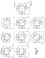
- Figures 7a-7i Examples of detector configurations are shown in Figures 7a-7i.
- Table 1 depicts the bore B x associated with each detector head for the configurations of Figure 7.
- the detector configurations shown in Figure 7 and Table 1 are not exhaustive.
- Figure Detector 2 Detector 3 7a B9 B3 7b B11 B1 7c B11 B5 7d B10 B4 7e B7 B1 7f B8 B2 7g B11 B5 7h B10 B4 7i B6 x
- Figures 7a-7f depict configurations for a three detector gantry.
- Figure 7b shows a three detector gantry with two of the detectors configured in a 180 degree opposed configuration. The opposed detectors provide anterior and posterior images. The third detector produces a lateral image which provides depth information.
- a transmission radiation source 300 may be substituted for one of the detectors.
- Figure 7i depicts a system having two heads configured in a 180 degree opposed configuration. Of course, four or more detectors can also be accommodated.
- Figure 7 and Table 1 are not an exhaustive list of the possible configurations. Other desirable configurations may readily be implemented by placing bores B x in other angular positions or by using different combinations of bores B x .
- a two detector gantry can be placed at any of the angular positions shown in Figure 7.
- a two detector gantry can be configured, for example, in 180 degree opposed, 90 degree orthogonal, or 102 degree orthogonal positions.
- the radial drives move the detectors 20 radially toward and away from the imaging region.
- the minimum aperture size and hence the minimum distance between the faces of the detectors and the patient is limited by the width of the detectors.
- the present invention permits the detectors 22 to be irised so that the minimum distance between the detector faces and the patient can be reduced from the limit otherwise defined by the detector widths.
- the tangential drives permit the detectors to be moved in a direction generally tangential to the imaging region.
- each detector face extends beyond the body of another detector.
- the width of each side of the aperture has a dimension smaller than the width of the corresponding detector. In this way, the detectors may be positions to define a variety of different aperture sizes.
- a four detector gantry is depicted in Figure 8f.
- Figures 8c and 8d depict a three detector gantry having two detectors arranged in a 90 degree configuration which is especially efficient for cardiac imaging.
- the minimum distance between the detector heads is ordinarily limited by the size of the detectors 20.
- the detectors can be positioned much nearer to the axis of rotation as shown in Figure 8d.
- variable angle multiple detector nuclear medicine gantry One benefit of the above-described variable angle multiple detector nuclear medicine gantry is that the configuration of the detectors may be readily changed. For example, the detectors may be placed in opposed, orthogonal, and 120 degree configurations. As a result, a single gamma camera may be used in a variety of applications. Another benefit is that the gamma camera may be produced with one or two detectors and readily upgraded to include additional detectors. The faces of the detectors may also be placed near to the patient while allowing relatively large detectors to be used. This improves the image quality of the gamma camera while enhancing the camera's flexibility in multiple applications.
Landscapes
- Health & Medical Sciences (AREA)
- Life Sciences & Earth Sciences (AREA)
- Medical Informatics (AREA)
- Engineering & Computer Science (AREA)
- Physics & Mathematics (AREA)
- High Energy & Nuclear Physics (AREA)
- Molecular Biology (AREA)
- Optics & Photonics (AREA)
- General Health & Medical Sciences (AREA)
- Nuclear Medicine, Radiotherapy & Molecular Imaging (AREA)
- Biomedical Technology (AREA)
- Pathology (AREA)
- Spectroscopy & Molecular Physics (AREA)
- Biophysics (AREA)
- General Physics & Mathematics (AREA)
- Radiology & Medical Imaging (AREA)
- Heart & Thoracic Surgery (AREA)
- Surgery (AREA)
- Animal Behavior & Ethology (AREA)
- Public Health (AREA)
- Veterinary Medicine (AREA)
- Nuclear Medicine (AREA)
Applications Claiming Priority (2)
| Application Number | Priority Date | Filing Date | Title |
|---|---|---|---|
| US08/757,874 US5838009A (en) | 1996-11-27 | 1996-11-27 | Variable angle multiple detector nuclear medicine gantry |
| US757874 | 1996-11-27 |
Publications (2)
| Publication Number | Publication Date |
|---|---|
| EP0846961A1 true EP0846961A1 (fr) | 1998-06-10 |
| EP0846961B1 EP0846961B1 (fr) | 2004-03-31 |
Family
ID=25049579
Family Applications (1)
| Application Number | Title | Priority Date | Filing Date |
|---|---|---|---|
| EP97309173A Expired - Lifetime EP0846961B1 (fr) | 1996-11-27 | 1997-11-14 | Gamma caméra |
Country Status (4)
| Country | Link |
|---|---|
| US (3) | US5838009A (fr) |
| EP (1) | EP0846961B1 (fr) |
| JP (1) | JP4323575B2 (fr) |
| DE (1) | DE69728358T2 (fr) |
Cited By (5)
| Publication number | Priority date | Publication date | Assignee | Title |
|---|---|---|---|---|
| EP0933652A3 (fr) * | 1998-02-02 | 2001-08-22 | Marconi Medical Systems, Inc. | Dispositif d'imagerie par émissions de positrons |
| EP0887662A3 (fr) * | 1997-05-30 | 2002-01-30 | Marconi Medical Systems, Inc. | Gamma caméra |
| WO2005040635A3 (fr) * | 2003-10-21 | 2005-06-30 | Forschungszentrum Juelich Gmbh | Tomographie d'emission monophotonique |
| GB2533861A (en) * | 2014-12-30 | 2016-07-06 | Morpho Detection Llc | Systems and methods for x-ray CT scanner with reconfigurable field of view |
| DE102016004624A1 (de) | 2016-04-13 | 2017-10-19 | Kurt Osterloh | Das Gammaauge: Ein Gerät zur Abbildung hochenergetisch strahlender Objekte |
Families Citing this family (81)
| Publication number | Priority date | Publication date | Assignee | Title |
|---|---|---|---|---|
| US5838009A (en) * | 1996-11-27 | 1998-11-17 | Picker International, Inc. | Variable angle multiple detector nuclear medicine gantry |
| US6175116B1 (en) * | 1997-06-02 | 2001-01-16 | Picker International, Inc. | Hybrid collimation and coincidence imager for simultaneous positron and single photon imaging |
| US6373060B1 (en) * | 1998-01-30 | 2002-04-16 | Kabushiki Kaisha Toshiba | Nuclear medicine diagnostic apparatus |
| US6201247B1 (en) * | 1998-04-02 | 2001-03-13 | Picker International, Inc. | Line source for gamma camera |
| WO2000062093A1 (fr) | 1999-04-14 | 2000-10-19 | Juni Jack E | Système de tomographie d'émission monophotonique |
| US7105825B2 (en) * | 1999-04-14 | 2006-09-12 | Juni Jack E | Single photon emission computed tomography system |
| US7767972B2 (en) * | 1999-04-14 | 2010-08-03 | Juni Jack E | Single photon emission computed tomography system |
| US7015476B2 (en) * | 1999-04-14 | 2006-03-21 | Juni Jack E | Single photon emission computed tomography system |
| EP1208390A4 (fr) | 1999-06-06 | 2003-10-08 | Elgems Ltd | Camera gamma et systeme de tomographie assiste par ordinateur |
| US6878941B2 (en) * | 2002-04-09 | 2005-04-12 | Elgems Ltd. | Gamma camera and CT system |
| JP2003520348A (ja) * | 2000-01-14 | 2003-07-02 | バン・ドウルメン,アドリアヌス・エイ | 単光子放出型コンピュータ撮影法による撮像方法 |
| US6617582B2 (en) * | 2000-07-21 | 2003-09-09 | Is2 Research Inc. | Scintillation camera having multiple fields of view |
| US8036731B2 (en) | 2001-01-22 | 2011-10-11 | Spectrum Dynamics Llc | Ingestible pill for diagnosing a gastrointestinal tract |
| US8489176B1 (en) | 2000-08-21 | 2013-07-16 | Spectrum Dynamics Llc | Radioactive emission detector equipped with a position tracking system and utilization thereof with medical systems and in medical procedures |
| US8565860B2 (en) | 2000-08-21 | 2013-10-22 | Biosensors International Group, Ltd. | Radioactive emission detector equipped with a position tracking system |
| US8909325B2 (en) | 2000-08-21 | 2014-12-09 | Biosensors International Group, Ltd. | Radioactive emission detector equipped with a position tracking system and utilization thereof with medical systems and in medical procedures |
| US6577890B1 (en) * | 2000-09-08 | 2003-06-10 | Koninklijke Philips Electronics, N.V. | Methodology to optimize positioning of multi-detector gamma cameras utilizing tangential detector motion |
| JP2004533607A (ja) * | 2001-01-16 | 2004-11-04 | ボード・オブ・リージェンツ,ザ・ユニヴァーシティ・オヴ・テキサス・システム | 個々に回転可能な検出器モジュールおよび/または個々に移動可能なシールド部分を備えるpetカメラ |
| GR1003828B (el) * | 2001-02-16 | 2002-03-04 | Εθνικο Κεντρο Ερευνας Φυσικων Επιστημων "Δημοκριτος" (Ιρρπ) | Τομογραφικη spect camera υψηλης χωρικης διακριτικης ικανοτητας (υχδι) |
| CA2448736C (fr) | 2001-06-05 | 2010-08-10 | Mikro Systems, Inc. | Procedes de fabrication de dispositifs tridimensionnels, et dispositifs crees par ces procedes |
| US7785098B1 (en) | 2001-06-05 | 2010-08-31 | Mikro Systems, Inc. | Systems for large area micro mechanical systems |
| US7141812B2 (en) * | 2002-06-05 | 2006-11-28 | Mikro Systems, Inc. | Devices, methods, and systems involving castings |
| US6728583B2 (en) * | 2001-06-27 | 2004-04-27 | Koninklijke Philips Electronics N.V. | User interface for a gamma camera which acquires multiple simultaneous data sets |
| US6762411B2 (en) * | 2002-03-13 | 2004-07-13 | Siemens Medical Solutions Usa, Inc. | Reconfigure lock for dual detector gamma camera |
| US7262415B2 (en) * | 2002-06-02 | 2007-08-28 | Crosetto Dario B | Gantry for geometrically configurable and non-configurable positron emission tomography detector arrays |
| JP4409865B2 (ja) * | 2003-06-20 | 2010-02-03 | 株式会社東芝 | 核医学診断装置 |
| US20040262525A1 (en) * | 2003-06-30 | 2004-12-30 | Yunker David A | Nuclear medicine gantry and method |
| US8586932B2 (en) * | 2004-11-09 | 2013-11-19 | Spectrum Dynamics Llc | System and method for radioactive emission measurement |
| US10964075B2 (en) | 2004-01-13 | 2021-03-30 | Spectrum Dynamics Llc | Gating with anatomically varying durations |
| US9470801B2 (en) | 2004-01-13 | 2016-10-18 | Spectrum Dynamics Llc | Gating with anatomically varying durations |
| US8571881B2 (en) | 2004-11-09 | 2013-10-29 | Spectrum Dynamics, Llc | Radiopharmaceutical dispensing, administration, and imaging |
| US9040016B2 (en) | 2004-01-13 | 2015-05-26 | Biosensors International Group, Ltd. | Diagnostic kit and methods for radioimaging myocardial perfusion |
| CN1981210A (zh) | 2004-01-13 | 2007-06-13 | 光谱动力学有限责任公司 | 多维图像重构 |
| US8280124B2 (en) | 2004-06-01 | 2012-10-02 | Spectrum Dynamics Llc | Methods of view selection for radioactive emission measurements |
| EP1778957A4 (fr) | 2004-06-01 | 2015-12-23 | Biosensors Int Group Ltd | Optimisation de la mesure d'emissions radioactives dans des structures corporelles specifiques |
| US7468513B2 (en) * | 2004-06-18 | 2008-12-23 | The Children's Hospital Of Philadelphia | Fast dynamic imaging protocol using a multi-head single photon emission computed tomography system |
| US7310407B2 (en) * | 2004-09-03 | 2007-12-18 | Juni Jack E | Nuclear medical imaging device |
| US7335888B2 (en) * | 2004-09-24 | 2008-02-26 | Siemens Medical Solutions Usa, Inc. | Imaging apparatus to acquire tomography projections with improved orbit |
| US9316743B2 (en) | 2004-11-09 | 2016-04-19 | Biosensors International Group, Ltd. | System and method for radioactive emission measurement |
| US8606349B2 (en) | 2004-11-09 | 2013-12-10 | Biosensors International Group, Ltd. | Radioimaging using low dose isotope |
| US9943274B2 (en) | 2004-11-09 | 2018-04-17 | Spectrum Dynamics Medical Limited | Radioimaging using low dose isotope |
| US8423125B2 (en) | 2004-11-09 | 2013-04-16 | Spectrum Dynamics Llc | Radioimaging |
| US10136865B2 (en) | 2004-11-09 | 2018-11-27 | Spectrum Dynamics Medical Limited | Radioimaging using low dose isotope |
| US8615405B2 (en) | 2004-11-09 | 2013-12-24 | Biosensors International Group, Ltd. | Imaging system customization using data from radiopharmaceutical-associated data carrier |
| WO2008059489A2 (fr) | 2006-11-13 | 2008-05-22 | Spectrum Dynamics Llc | Application à la radioimagerie de nouvelles formules de téboroxime |
| US7233002B2 (en) * | 2004-11-25 | 2007-06-19 | Ultraspect Ltd. | SPECT gamma camera with a fixed detector radius of orbit |
| US7265356B2 (en) * | 2004-11-29 | 2007-09-04 | The University Of Chicago | Image-guided medical intervention apparatus and method |
| JP2008524574A (ja) * | 2004-12-17 | 2008-07-10 | コーニンクレッカ フィリップス エレクトロニクス エヌ ヴィ | ガントリシステム |
| US8837793B2 (en) | 2005-07-19 | 2014-09-16 | Biosensors International Group, Ltd. | Reconstruction stabilizer and active vision |
| US8644910B2 (en) | 2005-07-19 | 2014-02-04 | Biosensors International Group, Ltd. | Imaging protocols |
| US7408162B2 (en) * | 2005-09-29 | 2008-08-05 | Siemens Medical Solutions Usa, Inc. | Method for reducing nuclear medicine scanning time |
| DE102005054226A1 (de) * | 2005-11-14 | 2007-05-24 | Siemens Ag | Bildgebende medizinische Modalität |
| JP4817055B2 (ja) * | 2006-03-03 | 2011-11-16 | 株式会社島津製作所 | マンモグラフィ装置 |
| US20070228282A1 (en) * | 2006-03-21 | 2007-10-04 | Frezghi Habte | Rectangular detector geometry for positron emission tomography |
| US8894974B2 (en) | 2006-05-11 | 2014-11-25 | Spectrum Dynamics Llc | Radiopharmaceuticals for diagnosis and therapy |
| WO2008075362A2 (fr) | 2006-12-20 | 2008-06-26 | Spectrum Dynamics Llc | Procédé, système et appareil pour utiliser et traiter des données multidimensionnelles |
| US8521253B2 (en) | 2007-10-29 | 2013-08-27 | Spectrum Dynamics Llc | Prostate imaging |
| WO2009090571A2 (fr) * | 2008-01-18 | 2009-07-23 | Koninklijke Philips Electronics, N.V. | Reconstruction de multiples segments |
| US9315663B2 (en) | 2008-09-26 | 2016-04-19 | Mikro Systems, Inc. | Systems, devices, and/or methods for manufacturing castings |
| JP4703703B2 (ja) * | 2008-09-30 | 2011-06-15 | 株式会社東芝 | 核医学診断装置 |
| US8049176B1 (en) * | 2008-12-12 | 2011-11-01 | Jefferson Science Assocates, LLC | Method and apparatus for real time imaging and monitoring of radiotherapy beams |
| KR101123951B1 (ko) * | 2009-05-13 | 2012-04-12 | 서울대학교산학협력단 | 가변형상 적응형 양전자 방출 단층촬영장치 및 이를 이용한 촬영방법 |
| US8338788B2 (en) | 2009-07-29 | 2012-12-25 | Spectrum Dynamics Llc | Method and system of optimized volumetric imaging |
| WO2012011083A1 (fr) * | 2010-07-22 | 2012-01-26 | Lip - Laboratório De Instrumentação E Física Experimental De Partículas | Appareil de contrôle pour thérapie par rayonnement photonique |
| US8859974B2 (en) * | 2010-12-16 | 2014-10-14 | General Electric Company | Adjustable spect detector |
| GB2494123A (en) * | 2011-08-30 | 2013-03-06 | Ucl Business Plc | Radiation Detector |
| US8813824B2 (en) | 2011-12-06 | 2014-08-26 | Mikro Systems, Inc. | Systems, devices, and/or methods for producing holes |
| US10987069B2 (en) | 2012-05-08 | 2021-04-27 | Spectrum Dynamics Medical Limited | Nuclear medicine tomography systems, detectors and methods |
| US9662079B2 (en) | 2013-09-03 | 2017-05-30 | General Electric Company | Methods and apparatus for imaging with detectors having moving detector heads |
| US9144411B2 (en) | 2013-09-03 | 2015-09-29 | General Electric Company | Methods and systems for controlling movement of detectors having multiple detector heads |
| JP2015100575A (ja) | 2013-11-26 | 2015-06-04 | 株式会社日立製作所 | 放射線撮像装置、放射線撮像方法および核医学診断装置 |
| US9029791B1 (en) | 2013-12-20 | 2015-05-12 | General Electric Company | Imaging system using independently controllable detectors |
| US9439607B2 (en) | 2013-12-20 | 2016-09-13 | General Electric Company | Detector arm systems and assemblies |
| ES2751069T3 (es) * | 2014-01-27 | 2020-03-30 | Epica Int Inc | Dispositivo de imagen radiológica con funcionamiento mejorado |
| US9510793B2 (en) | 2014-01-27 | 2016-12-06 | Epica International, Inc. | Radiological imaging device with advanced sensors |
| US10126438B2 (en) | 2014-09-19 | 2018-11-13 | University Of Virginia Patent Foundation | Systems and methods for polarized nuclear imaging and spectroscopy |
| US20190209102A1 (en) * | 2016-08-08 | 2019-07-11 | Kromek Group, PLC | Transformable gamma cameras |
| WO2018053256A1 (fr) | 2016-09-15 | 2018-03-22 | Yuan Zheng | Systèmes et procédés d'imagerie et de spectroscopie nucléaires polarisées |
| US10213174B1 (en) | 2018-01-05 | 2019-02-26 | General Electric Company | Nuclear medicine imaging systems and methods having multiple detector assemblies |
| CN110769169B (zh) * | 2019-09-06 | 2022-04-22 | 南京航空航天大学 | 一种基于偶数阶编码阵列的编码孔伽马相机及其设计方法 |
| US12394050B2 (en) | 2022-11-18 | 2025-08-19 | GE Precision Healthcare LLC | Hybrid imaging detector configuration for computed tomography |
Citations (5)
| Publication number | Priority date | Publication date | Assignee | Title |
|---|---|---|---|---|
| US4409484A (en) * | 1981-09-28 | 1983-10-11 | Technicare Corporation | Brake assembly for rotatable scintillation detector |
| FR2697918A1 (fr) * | 1992-11-10 | 1994-05-13 | Gen Electric | Dispositif de scintigraphie. |
| US5349190A (en) * | 1991-12-02 | 1994-09-20 | Adac Laboratories | Adjustable triple-detector image data acquisition system |
| US5444252A (en) | 1991-05-23 | 1995-08-22 | Adac Laboratories | Adjustable dual-detector image data acquisition system |
| US5523571A (en) * | 1995-03-31 | 1996-06-04 | Siemens Medical Systems, Inc. | Versatile reconfigurable gantry for use in scintillation camera systems |
Family Cites Families (11)
| Publication number | Priority date | Publication date | Assignee | Title |
|---|---|---|---|---|
| US4213054A (en) * | 1977-12-30 | 1980-07-15 | Union Carbide Corporation | Transverse section brain imager scanning mechanism |
| IT8323481A0 (it) * | 1983-10-27 | 1983-10-27 | Selo | Apparecchiatura polivalente per esecuzione di rilevazioni normali e tomografiche mediante gamma camera. |
| JPS6183984A (ja) * | 1984-09-29 | 1986-04-28 | Shimadzu Corp | Ect装置 |
| JPH0462492A (ja) * | 1990-06-29 | 1992-02-27 | Toshiba Corp | 核医学診断装置 |
| US5097132A (en) * | 1990-11-21 | 1992-03-17 | Picker International, Inc. | Nuclear medicine camera system with improved gantry and patient table |
| FR2677447A1 (fr) * | 1991-06-07 | 1992-12-11 | Sopha Medical | Gamma camera tomographique munie d'un detecteur orientable. |
| IL105881A (en) * | 1993-06-02 | 1995-10-31 | Israel State | A lightweight head for a gamma camera and a gamma camera assembly that includes it |
| US5569924A (en) * | 1994-08-18 | 1996-10-29 | Picker International, Inc. | Transformable dual head spect camera system |
| JPH095442A (ja) * | 1995-06-23 | 1997-01-10 | Hitachi Medical Corp | 2検出器型シンチレーションカメラ |
| US5717212A (en) * | 1996-04-25 | 1998-02-10 | Picker International, Inc. | Three detector head gamma camera system with independently circumferentially positionable detector heads |
| US5838009A (en) * | 1996-11-27 | 1998-11-17 | Picker International, Inc. | Variable angle multiple detector nuclear medicine gantry |
-
1996
- 1996-11-27 US US08/757,874 patent/US5838009A/en not_active Expired - Lifetime
-
1997
- 1997-11-14 EP EP97309173A patent/EP0846961B1/fr not_active Expired - Lifetime
- 1997-11-14 DE DE69728358T patent/DE69728358T2/de not_active Expired - Lifetime
- 1997-11-27 JP JP32637697A patent/JP4323575B2/ja not_active Expired - Fee Related
-
1998
- 1998-05-07 US US09/074,236 patent/US5929446A/en not_active Expired - Lifetime
-
1999
- 1999-07-26 US US09/360,898 patent/US6114701A/en not_active Expired - Lifetime
Patent Citations (5)
| Publication number | Priority date | Publication date | Assignee | Title |
|---|---|---|---|---|
| US4409484A (en) * | 1981-09-28 | 1983-10-11 | Technicare Corporation | Brake assembly for rotatable scintillation detector |
| US5444252A (en) | 1991-05-23 | 1995-08-22 | Adac Laboratories | Adjustable dual-detector image data acquisition system |
| US5349190A (en) * | 1991-12-02 | 1994-09-20 | Adac Laboratories | Adjustable triple-detector image data acquisition system |
| FR2697918A1 (fr) * | 1992-11-10 | 1994-05-13 | Gen Electric | Dispositif de scintigraphie. |
| US5523571A (en) * | 1995-03-31 | 1996-06-04 | Siemens Medical Systems, Inc. | Versatile reconfigurable gantry for use in scintillation camera systems |
Cited By (9)
| Publication number | Priority date | Publication date | Assignee | Title |
|---|---|---|---|---|
| EP0887662A3 (fr) * | 1997-05-30 | 2002-01-30 | Marconi Medical Systems, Inc. | Gamma caméra |
| EP0933652A3 (fr) * | 1998-02-02 | 2001-08-22 | Marconi Medical Systems, Inc. | Dispositif d'imagerie par émissions de positrons |
| WO2005040635A3 (fr) * | 2003-10-21 | 2005-06-30 | Forschungszentrum Juelich Gmbh | Tomographie d'emission monophotonique |
| US7498580B2 (en) | 2003-10-21 | 2009-03-03 | Forschungszentrum Julich Gmbh | Tomographic device and method with translational movement between object and detector |
| GB2533861A (en) * | 2014-12-30 | 2016-07-06 | Morpho Detection Llc | Systems and methods for x-ray CT scanner with reconfigurable field of view |
| US10010296B2 (en) | 2014-12-30 | 2018-07-03 | Morpho Detection, Llc | Systems and methods for x-ray CT scanner with reconfigurable field of view |
| GB2533861B (en) * | 2014-12-30 | 2021-02-17 | Morpho Detection Llc | Systems and methods for X-ray CT scanner with reconfigurable field of view. |
| DE102016004624A1 (de) | 2016-04-13 | 2017-10-19 | Kurt Osterloh | Das Gammaauge: Ein Gerät zur Abbildung hochenergetisch strahlender Objekte |
| WO2017178568A1 (fr) | 2016-04-13 | 2017-10-19 | Kurt Osterloh | L'oeil gamma : appareil pour reproduire des objets émettant des rayonnements hautement énergétiques |
Also Published As
| Publication number | Publication date |
|---|---|
| US5838009A (en) | 1998-11-17 |
| DE69728358D1 (de) | 2004-05-06 |
| JPH10160851A (ja) | 1998-06-19 |
| US5929446A (en) | 1999-07-27 |
| JP4323575B2 (ja) | 2009-09-02 |
| EP0846961B1 (fr) | 2004-03-31 |
| DE69728358T2 (de) | 2005-02-24 |
| US6114701A (en) | 2000-09-05 |
Similar Documents
| Publication | Publication Date | Title |
|---|---|---|
| US5838009A (en) | Variable angle multiple detector nuclear medicine gantry | |
| US5569924A (en) | Transformable dual head spect camera system | |
| US7439514B1 (en) | Adjustable pinhole collimators method and system | |
| US7569826B2 (en) | Adjustable collimators method and system | |
| US5717212A (en) | Three detector head gamma camera system with independently circumferentially positionable detector heads | |
| US7723690B2 (en) | Adjustable slit collimators method and system | |
| EP0030713B1 (fr) | Dispositif associé à un calculateur pour l'obtention d'images tomographiques de la distribution d'un radiotraceur | |
| US7194062B2 (en) | Gamma camera and CT system | |
| US20100163736A1 (en) | Spect gamma camera with a fixed detector radius of orbit | |
| US5055687A (en) | Single photon emission ct apparatus | |
| JP6121665B2 (ja) | 計算機式断層写真法(ct)システム | |
| US20060124855A1 (en) | Constant radius single photon emission tomography | |
| US7375338B1 (en) | Swappable collimators method and system | |
| US20080087829A1 (en) | Single-photon emission computed tomography (SPECT) using helical scanning with multiplexing multi-pinhole apertures | |
| Uribe et al. | Basic imaging performance characteristics of a variable field of view PET camera using quadrant sharing detector design | |
| EP1996960A2 (fr) | Système d'imagerie médicale nucléaire utilisant des mesures de transmission à haut rendement | |
| US6577890B1 (en) | Methodology to optimize positioning of multi-detector gamma cameras utilizing tangential detector motion | |
| US20020008204A1 (en) | Scintillation camera having multiple fields of view | |
| US7470907B2 (en) | Cross-slit collimator method and system | |
| EP1120666A2 (fr) | Procédé et appareil comprenant un tomographe avec un ordinateur pour l'imagerie multicouches à épaisseurs variables | |
| US20240335176A1 (en) | Rotating nuclear medicine detector with two collimators | |
| US6762411B2 (en) | Reconfigure lock for dual detector gamma camera | |
| Golan | A compact CT/SPECT system for small-object imaging | |
| MENDES | CONTINUOUS SCINTILLATOR DETECTOR BLOCKS FOR SIMULTANEOUS PET-MR IMAGING OF THE HUMAN BRAIN |
Legal Events
| Date | Code | Title | Description |
|---|---|---|---|
| PUAI | Public reference made under article 153(3) epc to a published international application that has entered the european phase |
Free format text: ORIGINAL CODE: 0009012 |
|
| AK | Designated contracting states |
Kind code of ref document: A1 Designated state(s): DE FR IT |
|
| AX | Request for extension of the european patent |
Free format text: AL;LT;LV;MK;RO;SI |
|
| AKX | Designation fees paid | ||
| RBV | Designated contracting states (corrected) | ||
| 17P | Request for examination filed |
Effective date: 19981204 |
|
| RBV | Designated contracting states (corrected) |
Designated state(s): DE FR IT |
|
| RAP1 | Party data changed (applicant data changed or rights of an application transferred) |
Owner name: MARCONI MEDICAL SYSTEMS, INC. |
|
| 17Q | First examination report despatched |
Effective date: 20020521 |
|
| GRAP | Despatch of communication of intention to grant a patent |
Free format text: ORIGINAL CODE: EPIDOSNIGR1 |
|
| RTI1 | Title (correction) |
Free format text: GAMMA CAMERA |
|
| RAP1 | Party data changed (applicant data changed or rights of an application transferred) |
Owner name: PHILIPS MEDICAL SYSTEMS (CLEVELAND), INC. |
|
| RAP1 | Party data changed (applicant data changed or rights of an application transferred) |
Owner name: KONINKLIJKE PHILIPS ELECTRONICS N.V. |
|
| GRAS | Grant fee paid |
Free format text: ORIGINAL CODE: EPIDOSNIGR3 |
|
| GRAA | (expected) grant |
Free format text: ORIGINAL CODE: 0009210 |
|
| AK | Designated contracting states |
Kind code of ref document: B1 Designated state(s): DE FR IT |
|
| PG25 | Lapsed in a contracting state [announced via postgrant information from national office to epo] |
Ref country code: IT Free format text: LAPSE BECAUSE OF FAILURE TO SUBMIT A TRANSLATION OF THE DESCRIPTION OR TO PAY THE FEE WITHIN THE PRE;WARNING: LAPSES OF ITALIAN PATENTS WITH EFFECTIVE DATE BEFORE 2007 MAY HAVE OCCURRED AT ANY TIME BEFORE 2007. THE CORRECT EFFECTIVE DATE MAY BE DIFFERENT FROM THE ONE RECORDED.SCRIBED TIME-LIMIT Effective date: 20040331 |
|
| REF | Corresponds to: |
Ref document number: 69728358 Country of ref document: DE Date of ref document: 20040506 Kind code of ref document: P |
|
| ET | Fr: translation filed | ||
| REG | Reference to a national code |
Ref country code: FR Ref legal event code: D6 |
|
| PLBE | No opposition filed within time limit |
Free format text: ORIGINAL CODE: 0009261 |
|
| STAA | Information on the status of an ep patent application or granted ep patent |
Free format text: STATUS: NO OPPOSITION FILED WITHIN TIME LIMIT |
|
| 26N | No opposition filed |
Effective date: 20050104 |
|
| PGFP | Annual fee paid to national office [announced via postgrant information from national office to epo] |
Ref country code: FR Payment date: 20081125 Year of fee payment: 12 |
|
| REG | Reference to a national code |
Ref country code: FR Ref legal event code: ST Effective date: 20100730 |
|
| PG25 | Lapsed in a contracting state [announced via postgrant information from national office to epo] |
Ref country code: FR Free format text: LAPSE BECAUSE OF NON-PAYMENT OF DUE FEES Effective date: 20091130 |
|
| REG | Reference to a national code |
Ref country code: DE Ref legal event code: R082 Ref document number: 69728358 Country of ref document: DE Representative=s name: MEYER, MICHAEL, DIPL.-ING., DE |
|
| REG | Reference to a national code |
Ref country code: DE Ref legal event code: R082 Ref document number: 69728358 Country of ref document: DE Representative=s name: MEYER, MICHAEL, DIPL.-ING., DE Effective date: 20140331 Ref country code: DE Ref legal event code: R081 Ref document number: 69728358 Country of ref document: DE Owner name: KONINKLIJKE PHILIPS N.V., NL Free format text: FORMER OWNER: KONINKLIJKE PHILIPS ELECTRONICS N.V., EINDHOVEN, NL Effective date: 20140331 |
|
| PGFP | Annual fee paid to national office [announced via postgrant information from national office to epo] |
Ref country code: DE Payment date: 20150129 Year of fee payment: 18 |
|
| REG | Reference to a national code |
Ref country code: DE Ref legal event code: R119 Ref document number: 69728358 Country of ref document: DE |
|
| PG25 | Lapsed in a contracting state [announced via postgrant information from national office to epo] |
Ref country code: DE Free format text: LAPSE BECAUSE OF NON-PAYMENT OF DUE FEES Effective date: 20160601 |