EP0847038A2 - Représentation d'un train de données audio-visuelles synchronisé par une horloge logicielle dans un ordinateur personnel - Google Patents
Représentation d'un train de données audio-visuelles synchronisé par une horloge logicielle dans un ordinateur personnel Download PDFInfo
- Publication number
- EP0847038A2 EP0847038A2 EP97309609A EP97309609A EP0847038A2 EP 0847038 A2 EP0847038 A2 EP 0847038A2 EP 97309609 A EP97309609 A EP 97309609A EP 97309609 A EP97309609 A EP 97309609A EP 0847038 A2 EP0847038 A2 EP 0847038A2
- Authority
- EP
- European Patent Office
- Prior art keywords
- audio
- visual
- frequency
- time
- visual stream
- Prior art date
- Legal status (The legal status is an assumption and is not a legal conclusion. Google has not performed a legal analysis and makes no representation as to the accuracy of the status listed.)
- Withdrawn
Links
Images
Classifications
-
- G—PHYSICS
- G11—INFORMATION STORAGE
- G11B—INFORMATION STORAGE BASED ON RELATIVE MOVEMENT BETWEEN RECORD CARRIER AND TRANSDUCER
- G11B20/00—Signal processing not specific to the method of recording or reproducing; Circuits therefor
- G11B20/00007—Time or data compression or expansion
-
- G—PHYSICS
- G06—COMPUTING OR CALCULATING; COUNTING
- G06F—ELECTRIC DIGITAL DATA PROCESSING
- G06F1/00—Details not covered by groups G06F3/00 - G06F13/00 and G06F21/00
- G06F1/04—Generating or distributing clock signals or signals derived directly therefrom
- G06F1/08—Clock generators with changeable or programmable clock frequency
-
- G—PHYSICS
- G11—INFORMATION STORAGE
- G11B—INFORMATION STORAGE BASED ON RELATIVE MOVEMENT BETWEEN RECORD CARRIER AND TRANSDUCER
- G11B27/00—Editing; Indexing; Addressing; Timing or synchronising; Monitoring; Measuring tape travel
- G11B27/10—Indexing; Addressing; Timing or synchronising; Measuring tape travel
- G11B27/102—Programmed access in sequence to addressed parts of tracks of operating record carriers
- G11B27/105—Programmed access in sequence to addressed parts of tracks of operating record carriers of operating discs
-
- G—PHYSICS
- G11—INFORMATION STORAGE
- G11B—INFORMATION STORAGE BASED ON RELATIVE MOVEMENT BETWEEN RECORD CARRIER AND TRANSDUCER
- G11B27/00—Editing; Indexing; Addressing; Timing or synchronising; Monitoring; Measuring tape travel
- G11B27/10—Indexing; Addressing; Timing or synchronising; Measuring tape travel
- G11B27/19—Indexing; Addressing; Timing or synchronising; Measuring tape travel by using information detectable on the record carrier
- G11B27/28—Indexing; Addressing; Timing or synchronising; Measuring tape travel by using information detectable on the record carrier by using information signals recorded by the same method as the main recording
- G11B27/30—Indexing; Addressing; Timing or synchronising; Measuring tape travel by using information detectable on the record carrier by using information signals recorded by the same method as the main recording on the same track as the main recording
- G11B27/3027—Indexing; Addressing; Timing or synchronising; Measuring tape travel by using information detectable on the record carrier by using information signals recorded by the same method as the main recording on the same track as the main recording used signal is digitally coded
-
- H—ELECTRICITY
- H04—ELECTRIC COMMUNICATION TECHNIQUE
- H04N—PICTORIAL COMMUNICATION, e.g. TELEVISION
- H04N5/00—Details of television systems
- H04N5/76—Television signal recording
- H04N5/765—Interface circuits between an apparatus for recording and another apparatus
Definitions
- the present invention relates generally to data processing systems and. more particularly, to rendering an audio-visual stream in a personal computer using a software clock.
- DVD devices store audio-visual data in a highly compressed form and play the audio-visual data to a user. These devices have a read only memory (ROM).
- ROM read only memory
- the DVD CD-ROM disc is a super-density disc that can hold up to 18 gigabytes of audio, video and other types of data (e.g., menus, sub-pictures, graphics, etc.).
- the DVD devices store video images on the disc so that the images may be later recalled and displayed on a video display.
- DVD CD-ROM players retrieve and display video images that have been compressed under known video compression techniques like the International Standard Organization's (ISO) Motion Picture Expert Group (MPEG) techniques MPEG 1 and MPEG 2.
- ISO International Standard Organization's
- MPEG Motion Picture Expert Group
- MPEG 1 is an ISO standard defined in ISO/IEC 11172 that sets forth a standard format for storing and distributing audio and motion video. Some of the features of MPEG I include random access, fast forward, and reverse playback. Consequently, MPEG 1 has been used as the basis for video CDs and many video games.
- the goal of MPEG 1 is playback of digital audio and video using a standard compact disk with a bit rate of 1.416 Mbps. where 1.15 Mbps of this bit rate is designated for video.
- MPEG 2 extends MPEG I to cover a wider range of applications.
- MPEG 2 is an ISO standard as defined by ISO/IEC 13818.
- the primary application originally targeted by MPEG 2 was all-digital transmission of broadcast-quality video at bit rates of 4-9 Mbps.
- MPEG 2 has become useful for many other applications, such as high definition television, and MPEG 2 now supports bit rates of 1.5-60 Mbps.
- DVD devices can also read and play compressed audio sequences using known audio decompression techniques (e.g. , Dolby AC3, MPEG 1 or MPEG 2). As such, these systems are especially well-suited for playing audio-visual works. such as movies.
- the DVD device When playing an audio-visual work like a movie, the DVD device reads an audio-visual stream from the DVD CD-ROM and displays the video portion of the stream on the video display and plays the audio portion of the stream on a speaker.
- the stream is stored on the CD-ROM using time stamps from a 27 MHz clock to indicate when a particular portion of the stream is to be played. These time stamps from the 27 MHz clock are also used to synchronize the audio and video portion of the stream at playtime. Otherwise, if the audio and video portion fell out of synchronization, the quality of the performance of the audio-visual work would greatly suffer (the viewer would notice a loss of lip synchronization).
- DVD devices have been developed, they are typically stand-alone devices and have not been integrated with other systems. However, by integrating the functionality of a DVD device with a personal computer, additional functionality can be provided to a user. It is therefore desirable to integrate a DVD device into an existing system like a personal computer.
- a DVD CD-ROM player is integrated with a personal computer.
- the stream from the DVD CD-ROM utilizes a 27 MHz clock; however, a personal computer typically does not have a 27 MHz clock, but has a system clock that runs at the frequency of the processor ( e.g. , 133 MHz). Therefore, in order to play (or render) a DVD-based audio-visual work in a personal computer, a clock running at 27 MHz is needed.
- One solution to this problem may be to provide an additional clock through the use of hardware circuitry. However, this approach is expensive and time-consuming in terms of development time.
- the DVD CD-ROM player utilizes a software-generated 27 MHz clock to facilitate rendering audio-visual streams in a personal computer.
- a software clock emulation running at 27 MHz By providing a software clock emulation running at 27 MHz, synchronization of the audio-visual stream is facilitated and both cost and development time are reduced.
- a method in an audio-visual rendering device having a system clock with a first frequency.
- the audio-visual rendering device renders an audio-visual stream synchronized to a second frequency.
- the method provides a software clock that runs at the second frequency and receives a portion of the audio-visual stream having an associated play time.
- the method determines when to render the portion of the audio-visual stream by comparing a value of the software clock to the associated play time, and when it is determined to render the portion of the audio-visual stream, the method renders the portion of the audio-visual stream.
- an audio-visual rendering device comprises a processor, a DVD drive, a video display, a speaker, and a memory.
- the processor has a system clock running at a first frequency.
- the DVD drive generates an audio-visual stream synchronized to a second frequency.
- the video display displays a video portion of the audio-visual stream.
- the speaker plays an audio portion of the audio-visual stream.
- the memory contains a software clock running at the second frequency and a program.
- the program receives the audio-visual stream from the DVD drive, examines the software clock to determine whether it is time to render a part of the audio-visual stream, and renders the part of the audio-visual stream when it is determined that it is time to render the part of the audio-visual stream.
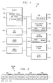
- Figure 1 depicts a computer system that is suitable for practicing a preferred embodiment of the present invention.
- Figure 2 depicts a format of the audio-visual stream received by the DVD player of Figure 1.
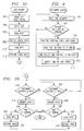
- Figures 3A and 3B depict a flowchart of the steps performed by the DVD player depicted in Figure 1.
- Figure 4 depicts a flowchart of the steps performed by the software clock of the DVD player depicted in Figure 1.
- the stream from the DVD CD-ROM utilizes a 27 MHz clock; however, a PC typically only has one clock, a system clock, that runs at the frequency of the processor (e.g., 133 MHz). Therefore. in order to play (or render) a DVD-based audio-visual work in a PC, a clock running at 27 MHz is needed.
- One solution to this problem may be to provide an additional clock through the use of hardware circuitry. However, this approach is expensive and time-consuming in terms of development time.
- a preferred embodiment of the present invention provides a software-generated 27 MHz clock to facilitate rendering audio-visual streams from a DVD CD-ROM in a PC.
- a software clock running at 27 MHz By providing a software clock running at 27 MHz, synchronization of the audio-visual stream is facilitated and both cost and development time are reduced.
- a preferred embodiment makes use of the time-stamp counter of the PENTIUM processor sold by Intel Corporation of Santa Clara, Califomia.
- the time-stamp counter is a counter running at the frequency of the processor.
- the software clock of a preferred embodiment utilizes the time-stamp counter to keep time, but scales down the time-stamp counter so that the software clock runs at 27 MHz.
- FIG. 1 depicts a computer system 100 that is suitable for practicing a preferred embodiment of the present invention.
- the computer system 100 contains a memory 102: a central processing unit (CPU) 104, such as the PENTIUM processor; a DVD CD-ROM ("DVD drive") 106; a video display subsystem 108, including a video controller 124 and a video display 126; a sound subsystem 110, including an audio controller 128 and a speaker 130; an audio decoder 112; a video decoder 114; a secondary storage device 116; and an input device 118.
- a DVD drive suitable for use in the computer system 100 is the DVD drive available from Panasonic Corporation of Secaucus, New Jersey.
- a suitable video decoder is the STI 3520A video decoder
- an example of a suitable audio decoder is the STI 4600 audio decoder. where both are available from SGS-Thomson Microelectronics, Inc. of Dallas, Texas.
- the memory 102 contains an operating system 120, such as the MICROSOFT® WINDOWS® 95 operating system available from Microsoft Corporation of Redmond, Washington, and a DVD player program 122.
- the DVD player program 122 is responsible for reading an audio-visual stream from the DVD drive 106, decoding the audio-visual stream using the audio decoder 112 and the video decoder 114, and rendering both the audio portion of the audio-visual stream and the video portion of the audio-visual stream on the sound subsystem 110 and the video display subsystem 108, respectively, at the appropriate time and in synchronization.
- the DVD player 122 uses a software clock 124 which executes on a thread separate from the DVD player. Since the software clock 124 executes on a separate thread, it runs asynchronously with respect to the DVD player 122 and is scheduled for the CPU 104 separately from the DVD player.
- the software clock 124 could be implemented as a separate process or other software entity.
- the software clock 124 is a counter running at 27 MHz and is based on the time counter 126 of the CPU 104.
- Both the audio decoder 112 and the video decoder 114 are implemented as hardware circuits using conventional techniques for decoding the audio or video data, like MPEG 1, MPEG 2, or AC3.
- the DVD player 122 reads the audio-visual stream from the DVD drive 106 and renders the audio-visual stream using the video display subsystem 108 and the sound subsystem 110.
- the DVD player 122 operates as a driver under control of the operating system 120 and utilizes the operating system to access the DVD drive 106.
- the DVD player 122 reads the audio-visual stream by requesting the operating system 120 to open a file on the DVD drive 106 that contains the audio-visual stream and by reading the stream from the DVD drive using normal file system calls of the operating system.
- the audio-visual stream 200 comprises a number of frames 202, 204, 206, and 208.
- Each frame stores either audio data or video data and has a universal system clock reference (SCR) 210, which is a derivative of a 27 MHz time base. All rendering of video and audio data should be performed with respect to the universal system clock reference to ensure a proper performance of the audio-visual work, and prevent problems like lip synchronization problems from occurring.
- SCR system clock reference
- each frame has a presentation time stamp (PTS), either an APTS for audio or a VPTS for video.
- This presentation time stamp (e.g., 212) contains a value that, when reached by a clock initialized to the SCR 210 and running at 27 MHz, indicates that the corresponding audio data (ADATA) or video data (VDATA) should be rendered.
- Figures 3A and 3B depict a flow chart of the steps performed by the DVD player 122.
- the first step performed by the DVD player is to read the first occurring SCR from the audio-visual stream (step 302).
- the DVD player stores the SCR into the time-stamp counter of the CPU and starts the software clock, which runs at 27 MHz (step 304).
- the DVD player starts a separate thread for executing the software clock using the well-known create thread system call of the VINDOWS® 95 operating system.
- all audio and video data is rendered with respect to the value of the software clock.
- the DVD player reads a presentation time stamp (APTS) from the first audio frame encountered (step 306).
- APTS presentation time stamp
- the DVD player After reading the APTS, the DVD player invokes the audio decoder 112 to decode the audio data corresponding to the APTS (step 308). The DVD player then reads the presentation time stamp (VPTS) from the first video frame encountered in the audio-visual stream (step 310) and invokes the video decoder 114 to decode the video data (step 312).
- VPTS presentation time stamp
- the DVD player accesses the software clock to determine if its value is greater than or equal to the APTS (step 314 in Figure 3B). If the software clock, which is running at 27 MHz, has a value greater than or equal to the APTS, it is time for the DVD player to invoke the sound subsystem 110 to render the audio. Therefore, when the value of the software clock is greater than or equal to the APTS, the DVD player renders the audio (step 316). In this step, the DVD player passes the decoded audio data to the sound subsystem where the sound subsystem then plays the audio data on the speaker. After rendering the audio, the DVD player determines if the end of the audio-visual stream has been reached (step 318).
- step 320 the DVD player reads the APTS from the next-encountered audio frame (step 320) and invokes the audio decoder to decode the audio data (step 322). Processing then continues to step 314.
- step 314 the value of the software clock is not greater than or equal to the APTS, the DVD player determines if the software clock's value is greater than or equal to the VPTS (step 324). If the software clock's value is not greater than or equal to the VPTS, processing continues to step 314. However, if the software clock's value is greater than or equal to the VPTS, the DVD player passes the decoded video data to the video subsystem to render the video (step 326). After rendering the video, the DVD player determines if the end of the audio-visual stream has been reached (step 328). If the end of the audio-visual stream has been reached, processing ends. If, however, the end of the audio-visual stream has not been reached, the DVD player reads the next encountered video frame to obtain a VPTS (step 330), decodes the corresponding video data (step 332), and proceeds to step 314.
- the software clock running at 27 MHz plays an integral role in rendering the audio-visual stream.
- this software clock uses the time-stamp counter of the PENTIUM processor to keep time and scales the value of the time-stamp counter into a 27 MHz value used by the software clock.
- the time-stamp counter is used for initially storing the SCR and for updating the software clock. but the current value of the 27 MHz clock is kept in software.
- the software clock runs as a separate thread within the DVD player. As such, the software clock runs asynchronously with respect to the DVD player, is scheduled for execution by the CPU separately from the DVD player, and has its own context information and register values.
- Figure 4 depicts a flow chart of the steps performed by the software clock of a preferred embodiment of the present invention after its thread is created by the DVD player.
- the first step performed by the software clock is to read the current value of the time counter (step 402).
- the software clock must directly emit a specific opcode (0xF31) to the processor to obtain the time counter's current value. since available programming languages do not typically provide access to the time counter.
- a 64-bit current time value is obtained where the low-order 32 bits are contained in the processor's EAX register and the high-order 32 bits are contained in the processor's EDX register.
- Code Table No. 1 contains exemplary code written in Microsoft Visual C++ version 4.0 that reads the current time from the time counter.
- the software clock determines whether the read time value should be updated (step 404).
- the software clock maintains a variable ("clock 27") which contains the current value of the software clock.
- the software clock determines whether the read time value should be updated by determining whether a sufficient number of clock ticks of the time counter, which runs at a faster frequency (e.g., 133 MHz), have occurred to warrant increasing the 27 MHz clock. For example, if the processor was running at 54 MHz, the 27 MHz clock would need to be updated one tick for every two ticks of the time counter.
- step 402. determines that the clock 27 variable does not need to be updated. If the software clock determines that the clock 27 variable does not need to be updated, processing continues to step 402. However, if the clock 27 variable does need to be updated, the software clock determines the amount of time relative to the time counter that has passed since the clock 27 variable was last updated (step 406) and scales this time interval to 27 MHz (step 408). This processing is described in greater detail below. Next, the software clock adds the scaled time interval to the clock 27 variable (step 410) and updates the indication of the last time that the clock 27 variable was updated (step 412). Pseudocode describing the processing of steps 404-412 is provided below in Code Table No. 2.
- step 402. It should be appreciated that the software clock continues to execute until the DVD player terminates the thread.
Landscapes
- Engineering & Computer Science (AREA)
- Theoretical Computer Science (AREA)
- Signal Processing (AREA)
- Multimedia (AREA)
- General Physics & Mathematics (AREA)
- General Engineering & Computer Science (AREA)
- Physics & Mathematics (AREA)
- Signal Processing For Digital Recording And Reproducing (AREA)
- Television Signal Processing For Recording (AREA)
- Indexing, Searching, Synchronizing, And The Amount Of Synchronization Travel Of Record Carriers (AREA)
- Synchronizing For Television (AREA)
- Compression Or Coding Systems Of Tv Signals (AREA)
- Processing Or Creating Images (AREA)
Applications Claiming Priority (2)
| Application Number | Priority Date | Filing Date | Title |
|---|---|---|---|
| US08/762,616 US5889515A (en) | 1996-12-09 | 1996-12-09 | Rendering an audio-visual stream synchronized by a software clock in a personal computer |
| US762616 | 1996-12-09 |
Publications (2)
| Publication Number | Publication Date |
|---|---|
| EP0847038A2 true EP0847038A2 (fr) | 1998-06-10 |
| EP0847038A3 EP0847038A3 (fr) | 1999-11-03 |
Family
ID=25065594
Family Applications (1)
| Application Number | Title | Priority Date | Filing Date |
|---|---|---|---|
| EP97309609A Withdrawn EP0847038A3 (fr) | 1996-12-09 | 1997-11-28 | Représentation d'un train de données audio-visuelles synchronisé par une horloge logicielle dans un ordinateur personnel |
Country Status (3)
| Country | Link |
|---|---|
| US (1) | US5889515A (fr) |
| EP (1) | EP0847038A3 (fr) |
| JP (1) | JPH10308927A (fr) |
Cited By (1)
| Publication number | Priority date | Publication date | Assignee | Title |
|---|---|---|---|---|
| WO2003054686A3 (fr) * | 2001-12-17 | 2004-05-27 | Becomm Corp | Procede et systeme de synchronisation de rendu de contenu |
Families Citing this family (25)
| Publication number | Priority date | Publication date | Assignee | Title |
|---|---|---|---|---|
| US6128597A (en) * | 1996-05-03 | 2000-10-03 | Lsi Logic Corporation | Audio decoder with a reconfigurable downmixing/windowing pipeline and method therefor |
| US6230295B1 (en) | 1997-04-10 | 2001-05-08 | Lsi Logic Corporation | Bitstream assembler for comprehensive verification of circuits, devices, and systems |
| US6122619A (en) * | 1998-06-17 | 2000-09-19 | Lsi Logic Corporation | Audio decoder with programmable downmixing of MPEG/AC-3 and method therefor |
| US6301304B1 (en) | 1998-06-17 | 2001-10-09 | Lsi Logic Corporation | Architecture and method for inverse quantization of discrete cosine transform coefficients in MPEG decoders |
| US6334026B1 (en) | 1998-06-26 | 2001-12-25 | Lsi Logic Corporation | On-screen display format reduces memory bandwidth for time-constrained on-screen display systems |
| US6160847A (en) * | 1998-06-26 | 2000-12-12 | Lsi Logic Corporation | Detection mechanism for video channel underflow in MPEG-2 video decoding |
| US6108622A (en) * | 1998-06-26 | 2000-08-22 | Lsi Logic Corporation | Arithmetic logic unit controller for linear PCM scaling and decimation in an audio decoder |
| US6278838B1 (en) | 1998-06-26 | 2001-08-21 | Lsi Logic Corporation | Peak-ahead FIFO for DVD system stream parsing |
| US6473558B1 (en) | 1998-06-26 | 2002-10-29 | Lsi Logic Corporation | System and method for MPEG reverse play through dynamic assignment of anchor frames |
| US6061655A (en) * | 1998-06-26 | 2000-05-09 | Lsi Logic Corporation | Method and apparatus for dual output interface control of audio decoder |
| US6424796B2 (en) * | 1998-07-21 | 2002-07-23 | Gateway, Inc. | Optical storage media drive adapter for stand-alone use |
| JP4059410B2 (ja) * | 1998-10-07 | 2008-03-12 | 株式会社バンダイナムコゲームス | ゲーム装置及び情報記憶媒体 |
| US6414996B1 (en) | 1998-12-08 | 2002-07-02 | Stmicroelectronics, Inc. | System, method and apparatus for an instruction driven digital video processor |
| US7269785B1 (en) * | 1999-12-30 | 2007-09-11 | Genesis Microchip Inc. | Digital manipulation of video in digital video player |
| US20040226020A1 (en) * | 2000-09-28 | 2004-11-11 | Ati Technologies, Inc. | Method and system for using general and appliance operating systems in a single information handling device |
| US7720354B2 (en) * | 2001-01-04 | 2010-05-18 | Apple Inc. | Embedded access information for digital versatile disc (DVD) independent of DVD player software |
| US7206367B1 (en) * | 2001-07-10 | 2007-04-17 | Sigmatel, Inc. | Apparatus and method to synchronize multimedia playback over a network using out-of-band signaling |
| US20030187730A1 (en) * | 2002-03-27 | 2003-10-02 | Jai Natarajan | System and method of measuring exposure of assets on the client side |
| US20040078828A1 (en) * | 2002-10-18 | 2004-04-22 | Parchman Travis Randall | Recovering timing for television services |
| US8190001B2 (en) * | 2003-06-12 | 2012-05-29 | Mark Bernsley | Method for creating and exhibiting multidimensional interactive stories |
| KR101015811B1 (ko) * | 2003-09-23 | 2011-02-22 | 엘지전자 주식회사 | UPnP 기반의 미디어 콘텐츠 재생을 제어하는 전자기기 및 그 방법 |
| JP2008517343A (ja) * | 2004-10-19 | 2008-05-22 | コーニンクレッカ フィリップス エレクトロニクス エヌ ヴィ | アニメーション・ジャダー補償 |
| US8020020B2 (en) * | 2008-02-28 | 2011-09-13 | Globalfoundries Inc. | Fast, automatically scaled processor time stamp counter |
| US9060187B2 (en) * | 2008-12-22 | 2015-06-16 | Netflix, Inc. | Bit rate stream switching |
| US8401370B2 (en) * | 2010-03-09 | 2013-03-19 | Dolby Laboratories Licensing Corporation | Application tracks in audio/video containers |
Family Cites Families (10)
| Publication number | Priority date | Publication date | Assignee | Title |
|---|---|---|---|---|
| US4575848A (en) * | 1984-02-01 | 1986-03-11 | Westinghouse Electric Corp. | Methods and apparatus for correcting a software clock from an accurate clock |
| JP2865782B2 (ja) * | 1990-03-16 | 1999-03-08 | 富士通株式会社 | 非同期伝送用codec装置 |
| JPH0643962A (ja) * | 1992-07-27 | 1994-02-18 | Fujitsu Ltd | ソフトウェア時計の時刻変更装置 |
| WO1994027234A1 (fr) * | 1993-05-10 | 1994-11-24 | Taligent, Inc. | Systeme de synchronisation multimedia |
| US5596696A (en) * | 1993-05-10 | 1997-01-21 | Object Technology Licensing Corp. | Method and apparatus for synchronizing graphical presentations |
| US5768629A (en) * | 1993-06-24 | 1998-06-16 | Discovision Associates | Token-based adaptive video processing arrangement |
| DE4423366C1 (de) * | 1994-07-04 | 1995-10-19 | Grundig Emv | Verfahren und Anordnung zum Betreiben einer Software-Uhr in einem Gerät der Unterhaltungselektronik |
| US5559999A (en) * | 1994-09-09 | 1996-09-24 | Lsi Logic Corporation | MPEG decoding system including tag list for associating presentation time stamps with encoded data units |
| TW295766B (fr) * | 1995-02-16 | 1997-01-11 | Siemens Ag | |
| EP0737975B1 (fr) * | 1995-04-11 | 1999-07-07 | Kabushiki Kaisha Toshiba | Milieu d'enregistrement et méthode, appareil d'enregistrement d'enregistrement pour enregistrer les données sur le milieu d'enregistrement, et appareil de reproduction et méthode de reproduction pour la reproduction de données du milieu d'enregistrement |
-
1996
- 1996-12-09 US US08/762,616 patent/US5889515A/en not_active Expired - Lifetime
-
1997
- 1997-11-28 EP EP97309609A patent/EP0847038A3/fr not_active Withdrawn
- 1997-12-09 JP JP9338504A patent/JPH10308927A/ja active Pending
Cited By (1)
| Publication number | Priority date | Publication date | Assignee | Title |
|---|---|---|---|---|
| WO2003054686A3 (fr) * | 2001-12-17 | 2004-05-27 | Becomm Corp | Procede et systeme de synchronisation de rendu de contenu |
Also Published As
| Publication number | Publication date |
|---|---|
| US5889515A (en) | 1999-03-30 |
| EP0847038A3 (fr) | 1999-11-03 |
| JPH10308927A (ja) | 1998-11-17 |
Similar Documents
| Publication | Publication Date | Title |
|---|---|---|
| US5889515A (en) | Rendering an audio-visual stream synchronized by a software clock in a personal computer | |
| US5951690A (en) | Synchronizing an audio-visual stream synchronized to a clock with a video display that is synchronized to a different clock | |
| EP0783824B1 (fr) | Procede et appareil programmables de synchronisation audio-video pour systemes multimedia | |
| US6512552B1 (en) | Subpicture stream change control | |
| US5959684A (en) | Method and apparatus for audio-video synchronizing | |
| US6297797B1 (en) | Computer system and closed caption display method | |
| US5617502A (en) | System and method synchronizing audio and video digital data signals during playback | |
| US20070248169A1 (en) | Method and Apparatus for Coding Information | |
| US6297852B1 (en) | Video display method and apparatus with synchronized video playback and weighted frame creation | |
| US20040168203A1 (en) | Method and apparatus for presenting video data in synchronization with text-based data | |
| US6670996B2 (en) | Apparatus and method for display of progressive and interland video content | |
| MXPA04010029A (es) | Despliegue de informacion de subtitulos durante modos de truco de video. | |
| WO1996019078A1 (fr) | Procede et appareil de synchronisation audio et video dans des systemes de reproduction mpeg | |
| CA2772021A1 (fr) | Support de stockage possedant un flux graphique interactif et appareil permettant de reproduire celui-ci | |
| US20030161614A1 (en) | Method and apparatus for playing back data recorded on a recoding medium | |
| US6249640B1 (en) | System and method for rapidly decoding sub-pictures in a DVD player | |
| US6587635B1 (en) | Subpicture master control | |
| EP1761057A1 (fr) | Dispositif de traitement des données, processus de traitement des données, programme, média d'enregistrement du programme, média d'enregistrement des données et structure des données | |
| KR100390028B1 (ko) | 동영상 재생장치의 온 스크린 디스플레이 제어시스템 및제어방법 | |
| EP1758120A1 (fr) | Dispositif de traitement de donnees, procede de traitement de donnees, programme, support d'enregistrement de programmes, support d'enregistrement de donnees, et structure de donnees | |
| US20050094973A1 (en) | Moving picture reproducing apparatus in which player mode information is set, reproducing method using the same, and storage medium | |
| RU2361294C2 (ru) | Способ и устройство синхронного воспроизведения записанного на интерактивный носитель записи основного содержимого и дополнительного содержимого к нему | |
| US8107796B2 (en) | Data processing device, data processing method, program, program recording medium, data recording medium, and data structure | |
| US20040199564A1 (en) | Apparatus and method for multimedia data stream production | |
| JP2003143522A (ja) | 再生装置及びその方法 |
Legal Events
| Date | Code | Title | Description |
|---|---|---|---|
| PUAI | Public reference made under article 153(3) epc to a published international application that has entered the european phase |
Free format text: ORIGINAL CODE: 0009012 |
|
| AK | Designated contracting states |
Kind code of ref document: A2 Designated state(s): DE FR GB IT |
|
| AX | Request for extension of the european patent |
Free format text: AL;LT;LV;MK;RO;SI |
|
| RAP3 | Party data changed (applicant data changed or rights of an application transferred) |
Owner name: STMICROELECTRONICS, INC. |
|
| PUAL | Search report despatched |
Free format text: ORIGINAL CODE: 0009013 |
|
| AK | Designated contracting states |
Kind code of ref document: A3 Designated state(s): AT BE CH DE DK ES FI FR GB GR IE IT LI LU MC NL PT SE |
|
| AX | Request for extension of the european patent |
Free format text: AL;LT;LV;MK;RO;SI |
|
| RIC1 | Information provided on ipc code assigned before grant |
Free format text: 6G 09G 5/00 A, 6G 09G 5/12 B, 6H 04N 7/62 B |
|
| 17P | Request for examination filed |
Effective date: 20000502 |
|
| AKX | Designation fees paid |
Free format text: DE FR GB IT |
|
| STAA | Information on the status of an ep patent application or granted ep patent |
Free format text: STATUS: THE APPLICATION HAS BEEN WITHDRAWN |
|
| 18W | Application withdrawn |
Withdrawal date: 20021118 |