EP0847122A2 - Protection thermique avec deux constantes de temps pour appareil de commutation électrique - Google Patents
Protection thermique avec deux constantes de temps pour appareil de commutation électrique Download PDFInfo
- Publication number
- EP0847122A2 EP0847122A2 EP97121322A EP97121322A EP0847122A2 EP 0847122 A2 EP0847122 A2 EP 0847122A2 EP 97121322 A EP97121322 A EP 97121322A EP 97121322 A EP97121322 A EP 97121322A EP 0847122 A2 EP0847122 A2 EP 0847122A2
- Authority
- EP
- European Patent Office
- Prior art keywords
- generating
- signal
- trip
- function
- motor
- Prior art date
- Legal status (The legal status is an assumption and is not a legal conclusion. Google has not performed a legal analysis and makes no representation as to the accuracy of the status listed.)
- Withdrawn
Links
Images


Classifications
-
- H—ELECTRICITY
- H02—GENERATION; CONVERSION OR DISTRIBUTION OF ELECTRIC POWER
- H02H—EMERGENCY PROTECTIVE CIRCUIT ARRANGEMENTS
- H02H6/00—Emergency protective circuit arrangements responsive to undesired changes from normal non-electric working conditions using simulators of the apparatus being protected, e.g. using thermal images
- H02H6/005—Emergency protective circuit arrangements responsive to undesired changes from normal non-electric working conditions using simulators of the apparatus being protected, e.g. using thermal images using digital thermal images
-
- H—ELECTRICITY
- H02—GENERATION; CONVERSION OR DISTRIBUTION OF ELECTRIC POWER
- H02P—CONTROL OR REGULATION OF ELECTRIC MOTORS, ELECTRIC GENERATORS OR DYNAMO-ELECTRIC CONVERTERS; CONTROLLING TRANSFORMERS, REACTORS OR CHOKE COILS
- H02P1/00—Arrangements for starting electric motors or dynamo-electric converters
- H02P1/16—Arrangements for starting electric motors or dynamo-electric converters for starting dynamo-electric motors or dynamo-electric converters
- H02P1/26—Arrangements for starting electric motors or dynamo-electric converters for starting dynamo-electric motors or dynamo-electric converters for starting an individual polyphase induction motor
- H02P1/28—Arrangements for starting electric motors or dynamo-electric converters for starting dynamo-electric motors or dynamo-electric converters for starting an individual polyphase induction motor by progressive increase of voltage applied to primary circuit of motor
Definitions
- This invention relates to a load protection circuit in an electrical switching apparatus and, more particularly, to an overload relay, for a load such as a motor, used in motor starters, motor controllers, and other load controllers.
- Electromagnetic contactors include a plurality of movable electrical contacts which are brought into contact with a plurality of fixed electrical contacts to close the contactor. The movable electrical contacts are separated from the fixed contacts to open the contactor. Examples of contactors are disclosed in U.S. Patent Numbers 4,760,364; and 4,766,273.
- a common type of starter for loads such as motors, lighting, and the like, comprises an electromagnetic contactor with an overload relay.
- the purpose of the overload relay is to estimate the heat produced in the motor by line current and "trip" or stop the motor if the retained heat exceeds an acceptable level.
- the overload relay monitors the load current and trips the contactor open if a persistent overcurrent condition exists.
- the overload relay tracks an I 2 t characteristic of the load current which is a measure of heating.
- An example of an overlad relay is disclosed in U.S. Patent Number 4,528,539.
- an I 2 t value is calculated from a sensed load current value I for a fixed time t . If the calculated I 2 t value is less than an accumulated I 2 t value, then the accumulated I 2 t value is updated by subtracting a cooling adjustment, which reflects cooling of the load, from the previously calculated accumulated I 2 t value. On the other hand, if the calculated I 2 t value is greater than or equal to the accumulated I 2 t value, then the accumulated I 2 t value is updated by adding a heating adjustment, which reflects heating of the load, to the previously calculated accumulated I 2 t value. When the accumulated I 2 t value reaches a trip level, the contactor is tripped open to interrupt the flow of current to the load.
- the thermal characteristic is modeled by a single thermal mass term associated with integration of heat of the load, and a single dissipation term associated with cooling of the load.
- the thermal mass term and the dissipation term combine to form a thermal time constant.
- the thermal mass may be represented electrically with a capacitor and the thermal dissipation or cooling term may be represented electrically with a resistor shunting the capacitor.
- Heat input to the load is analogous to a current source.
- Temperature rise is represented by the voltage developed across the capacitor as charged by current from the current source. In other words, the "heat input" from the current source less the "cooling" by the resistor is integrated by the capacitor.
- thermal overload relays are designed in various classes such as Classes 10, 20 and 30. In this system, the specific class is defined as the time in seconds for the load to operate at six times rated load current.
- known thermal overloads are not specifically designed for European Design N motors, or Design E or premium efficiency motors. See, e.g. , Revelt, J., "Don't Let The New Design E Motor Throw You A Curve,” Electrical Construction & Maintenance , pp. 31-32 and 34, March 1996.
- the trip curves (i.e ., trip time versus multiple of rated load current) for the Class 20 overload relay and the Design E motor are about the same for less than about two times rated load current. Nevertheless, such overload relay does not provide optimal starting capacity for the requirements of the Design E motor. For example, during periods of heavy overload, such as starting, the current for the Design E motor will be about eight times rated load current as compared to about six times rated load current for a conventional Design B motor.
- a European Design N motor provides an analogous problem. Therefore, nuisance tripping is likely to occur with systems that must start under a relatively large load, such as the starting current of a Design E motor or a European Design N motor. Hence, there is room for improvement.
- the present invention is directed to a motor starter for an electrical circuit including separable contact means for switching an electrical current flowing between a power source and a load; operating means responsive to a trip signal for opening and closing the separable contact means; means for sensing the electrical current flowing between the power source and the load and providing a sensed current value therefrom; and overload relay means for generating the trip signal as a function of the sensed current value, a first time constant and a second time constant.
- a motor starter for an electrical circuit includes electrical contactor means having separable contact means for switching an electrical current flowing between a power source and a load, and operating means responsive to a trip signal for opening and closing the separable contact means; means for sensing the electrical current flowing between the power source and the load and providing a sensed current value therefrom; and overload relay means for generating the trip signal as a function of the sensed current value, a first time constant and a second time constant.
- an electrical switching apparatus for an electrical circuit includes separable contact means for switching an electrical current flowing between a power source and a load; means responsive to a trip signal for moving the separable contact means from a closed position to an open position thereof; means for sensing the electrical current flowing between the power source and the load and providing a sensed current value therefrom; and means for generating the trip signal as a function of the sensed current value, a first time constant and a second time constant.
- signal shall expressly include, but not be limited to any input or output utilized for control and/or monitoring such as, for example, analog signals, digital signals, command signals, status signals, discrete signals, serial signals or serial messages.
- the invention has particular application and will be described in connection with a motor starter and, more particularly, a motor starter including an overload relay protection circuit and three-phase contactor contacts.
- a motor starter including an overload relay protection circuit and three-phase contactor contacts.
- the invention has broad application for controlling one or more contacts in electrical switching devices, such as circuit switching devices and circuit interrupters including circuit breakers, contactors, motor controllers, lighting controllers and other load controllers, utilized in other applications.
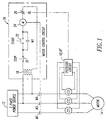
- a three-phase power and control system is shown in Figure 1.
- the system includes an overload relay protection circuit 10 ' incorporating the features of the invention.
- An overload relay protection circuit 10 similar to the circuit 10 ' , and reference numbers 12 through 62 employed herein are disclosed in U.S. Patent No. 5,222,009, which is hereby incorporated by reference.
- a three-phase power source 12 is coupled through contactor contacts M2,M3,M4 and sensors, such as respective current transformers CT1,CT2,CT3, to a three-phase motor 14 in typical manner. Either external or internal current transformers may be used.
- a single-phase start and control circuit 16 is used to control the supply of power to the motor 14.
- a step down transformer 18 is used to reduce the power (typically 208-600 volts AC) from two phases of the power source 12 to 120 volts AC.
- a normally closed STOP button 20 is provided to break the circuit and manually shut off the power supply to the motor 14.
- the normally open START button 22 is closed, energizing the coil (M) 24 and closing contacts M1,M2,M3,M4.
- Contact M1 interlocks the control circuit 16 in order that contacts M2,M3,M4 stay energized unless the control circuit 16 is opened at the STOP button 20 or is opened by the opening of the normally closed overload relay contact (OL) 26.
- the overload relay circuit 10 ' of the invention is connected to the secondaries of the three current transformers CT1,CT2,CT3 for monitoring or sensing the electrical load current flowing between the power source 12 and the motor 14, to provide sensed current values therefrom, and to detect the presence of an overload condition.
- the overload relay circuit 10 ' is activated to open the contact 26 and shut down the power supply to the motor 14. After certain events have occurred, the contact 26 will reclose to permit starting the motor 14.
- FIG. 2 An expanded functional block diagram of the overload relay circuit 10 ' is shown in Figure 2.
- Signal converters 52,54,56 are provided and are coupled to the current transformers CT1,CT2,CT3, respectively.
- the converters 52,54,56 convert the current at each phase of the motor 14 into a suitable filtered (AC) signal for input to the multiplexer of integrated circuit U1.
- the multiplexer continuously sequentially scans the outputs of the converters 52,54,56 to monitor the load level on each of the three phases of the windings (not shown) of the motor 14. This permits monitoring of each of the three power phases.
- the three monitored signals produced by the converters 52,54,56 are input to the multiplexer where they are combined to produce a single output which preserves the independent identity of each of the three inputs.
- This combined signal is input to a gain control circuit 60 where the current gain range can be set in accordance with the load specifications for each particular motor 14.
- the analog output I of the gain control circuit 60 is presented to the microprocessor ( ⁇ P) through the analog-to-digital (A/D) converter of integrated circuit U1.
- the trip sequence is initiated, and the trip signal T is output by the microprocessor of integrated circuit U1 to a relay drive circuit 62.
- the relay drive circuit 62 is coupled directly to the overload contact 26 of Figure 1.
- the normally closed contact 26 is opened, the coil 24 is deenergized, and the motor 14 is shut down.
- the relay drive circuit 62 and the overload contact 26 are possible such as a drive circuit for a contactor coil which initiates movement of an armature and closure of the separable contacts M2,M3,M4.
- such other embodiments may include an AC coil connected to an AC power source through a suitable AC switch such as a triac; or a DC coil connected to DC power derived from an AC power source by a diode bridge, in which a suitable current regulator controls DC current flowing through the DC coil with a suitable DC switch such as a field effect transistor.
- a suitable AC switch such as a triac
- a DC coil connected to DC power derived from an AC power source by a diode bridge, in which a suitable current regulator controls DC current flowing through the DC coil with a suitable DC switch such as a field effect transistor.
- a motor starter 64 includes an electrical contactor 66 having the separable contacts M2,M3,M4 for switching an electrical current flowing between the power source 12 and the motor 14, and an overload relay 68.
- the coil 24 (shown in Figure 1) of the motor control circuit 16 forms an operating circuit which is responsive to the two states of the trip signal T of the overload relay circuit 10 ' for moving the separable contacts M2,M3,M4 between the closed position of Figure 2 and the open position of Figure 1, thereby opening and closing such separable contacts.
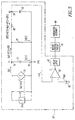
- the respective overload relay circuits 10 '' and 10 ' generate the trip signal T as a two time constant I 2 t function of the sensed current value I and time t .
- the overload relay circuit 10 ' is implemented with a digital circuit employing a processor such as the microcontroller or microprocessor.
- an analog circuit 10 '' may be employed as shown in Figure 3.
- a sensed analog current value i(m) (i.e. , I ) is suitably derived from one or more current sensors 72 such as the current transformers CT1,CT2,CT3 of Figure 1.
- a squaring circuit 74 provides an analog squared current value i(p) from the square of the analog sensed current value i(m) .
- a thermal mass is represented by a capacitor C1 and a dissipation term is represented by a resistor R1 which shunts the capacitor C1.
- Capacitor C1 is charged by the analog squared current value i(p) and is discharged, in part, by the resistor R1.
- the capacitor C1 is charged by the analog capacitor current i(C1) to form a voltage V1 at node 76 as referenced to ground GND at node 78.
- the capacitor C2 is charged by the analog capacitor current i(C2) to form an analog thermal protection voltage V2 at node 79 as referenced to ground GND at node 78.
- a comparator 80 compares the analog thermal protection voltage V2 at node 79 with an analog predetermined reference voltage V TRIP from a voltage reference 82. In the exemplary embodiment, the comparator 80 generates the trip signal T when the analog thermal protection voltage V2 is about greater than the analog predetermined reference voltage V TRIP .
- FIG 4 is a flowchart of a suitable overload relay routine 83 used by the microprocessor of integrated circuit U1 to trip the separable contacts M2,M3,M4 of Figure 2.
- the thermal model which mimics the analog thermal model of Figure 3.
- the thermal masses i.e. , capacitors C1 and C2
- the digital values employed in Figure 4 are analogous to the analog values of Figure 3 and, hence, similar labels are employed for the analog values of Figure 3 and the digital values of Figure 4.
- the digital values of the resistors R1,R2 of Figure 3 are preferably set to one ohm at step 84.
- the routine 83 generates the trip signal T as a function of the sensed current value I , a first time constant ⁇ 1 and a second time constant ⁇ 2 .
- an integer n is initialized to one.
- digital values i(C1) and i(C2) are initialized to zero.
- a digital squared value i(p) is obtained by squaring the digital sensed current value i(m) ( i.e. , I ) which is suitably derived from the current transformers CT1,CT2,CT3 of Figure 2.
- the third expression of Equation 3 is preferably employed, although the fourth (approximate) expression may also be employed.
- Step 100 similarly calculates a new digital thermal protection value V2(n) from the previously calculated value V2(n-1) plus a loop time dT times digital value i(C2) divided by C2.
- the digital thermal protection value V2 is increased as a function of the intermediate value V1 (as discussed with digital value i(C2) calculated at steps 92 and 94) and capacitor C2.
- the digital thermal protection value V2 is increased as a function of the intermediate value V1 and the time constant ⁇ 2 .
- the newly calculated digital thermal protection value V2(n) is compared with a digital predetermined trip value V TRIP . If the newly calculated digital thermal protection value V2(n) is greater than the digital predetermined trip value V TRIP , then, at step 104, the contactor 66 is opened by setting the trip signal T of Figure 2 to the appropriate state. Otherwise, at step 106, the contactor 66 remains closed and the integer n is incremented. After a suitable delay, at step 108, the routine repeats at step 90. The subsequent iteration of steps 90,92,94,96,98,100 calculates the next digital thermal protection value V2(n+1) .
- the execution time of the loop formed by steps 90 through 108 is about 1 mS, ⁇ 1 is about 500 S, and ⁇ 2 is about 10 S, although the invention is applicable to a wide range of such times.
- the exemplary overload relay 64 utilizes a four-term (i.e. , R1,C1,R2,C2) thermal model which more closely models the required motor protection curve for a motor such as a European Design N motor or a Design E motor. These four terms combine to form a circuit with two thermal time constants ⁇ 1 , ⁇ 2 .
- the two time constant circuit 10 '' utilizes the thermal protection voltage V2 developed across capacitor C2 to indicate the critical rise in temperature of the motor 14 of Figure 1. Since the European Design N or Design E motors are more complex than a single thermal mass term and a single thermal dissipation term, this two time constant model more closely models the true thermal impedance of such motors. Furthermore, the two time constant model is applicable to any motor which requires a motor protection curve having two time constants.
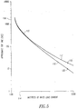
- Figure 5 illustrates a trip curve 110 of a conventional Class 20 overload and a trip curve 112 of the exemplary overload relay protection circuits 10 ' , 10 '' for a Design E motor.
- the horizontal X-axis 114 represents multiples of rated load current and the vertical Y-axis 116 represents approximate trip time (S).
- the trip curve 110 is a conventional first order trip curve which is a function of the sensed current value (I), a single time constant and time.
- the trip curve 112, as generated by the analog circuit 10 '' of Figure 3 or the routine 83 of Figure 4, is a second order trip curve and is a function of the sensed current value (I), a first time constant ( e.g. , ⁇ 1 ), a second time constant ( e.g. , ⁇ 2 ) and time.
- the current for the exemplary Design E motor will be approximately 800% ( e.g. , at point 118) of the rated load current.
- the additional time constant ( ⁇ 2 ) safely provides typically 183% times a current for a typical Class 20 overload as shown at point 120 of conventional trip curve 110.
- the design E trip curve 112 provides about 335% times the I 2 t of the conventional Class 20 overload trip curve 110.
- the trip curve as generated by the analog circuit 10 '' of Figure 3 or the routine 83 of Figure 4, safely provides about 357% times the current for the conventional Class 20 overload.
Landscapes
- Engineering & Computer Science (AREA)
- Power Engineering (AREA)
- Protection Of Generators And Motors (AREA)
- Emergency Protection Circuit Devices (AREA)
- Motor And Converter Starters (AREA)
- Stopping Of Electric Motors (AREA)
Applications Claiming Priority (2)
| Application Number | Priority Date | Filing Date | Title |
|---|---|---|---|
| US75397296A | 1996-12-04 | 1996-12-04 | |
| US753972 | 1996-12-04 |
Publications (2)
| Publication Number | Publication Date |
|---|---|
| EP0847122A2 true EP0847122A2 (fr) | 1998-06-10 |
| EP0847122A3 EP0847122A3 (fr) | 1999-08-18 |
Family
ID=25032940
Family Applications (1)
| Application Number | Title | Priority Date | Filing Date |
|---|---|---|---|
| EP97121322A Withdrawn EP0847122A3 (fr) | 1996-12-04 | 1997-12-04 | Protection thermique avec deux constantes de temps pour appareil de commutation électrique |
Country Status (3)
| Country | Link |
|---|---|
| EP (1) | EP0847122A3 (fr) |
| JP (1) | JPH10174275A (fr) |
| CN (1) | CN1190821A (fr) |
Cited By (3)
| Publication number | Priority date | Publication date | Assignee | Title |
|---|---|---|---|---|
| DE10010290A1 (de) * | 2000-03-02 | 2001-09-06 | Abb Patent Gmbh | Elektronisches Überlastrelais |
| WO2007047281A1 (fr) * | 2005-10-17 | 2007-04-26 | Siemens Energy & Automation, Inc. | Systeme, dispositif et procede de mise en oeuvre de relais de surintensite pour la protection des moteurs |
| DE102010026246A1 (de) * | 2010-07-01 | 2011-06-22 | Siemens Aktiengesellschaft, 80333 | Mehrpoliger Leistungsschalter, insbesondere für Niederspannungen |
Families Citing this family (2)
| Publication number | Priority date | Publication date | Assignee | Title |
|---|---|---|---|---|
| FI118659B (fi) * | 2004-02-02 | 2008-01-31 | Abb Oy | Terminen ylikuormitussuoja |
| CN114162744B (zh) * | 2021-11-05 | 2024-08-13 | 恒宏智能装备有限公司 | 一种带有限流保护器的电动千斤顶 |
Family Cites Families (1)
| Publication number | Priority date | Publication date | Assignee | Title |
|---|---|---|---|---|
| EP0135870A1 (fr) * | 1983-09-27 | 1985-04-03 | BBC Aktiengesellschaft Brown, Boveri & Cie. | Procédé et appareil pour la protection contre les surcharges des consommateurs d'énergie électrique |
-
1997
- 1997-11-28 JP JP32804197A patent/JPH10174275A/ja active Pending
- 1997-12-03 CN CN97125402A patent/CN1190821A/zh active Pending
- 1997-12-04 EP EP97121322A patent/EP0847122A3/fr not_active Withdrawn
Cited By (3)
| Publication number | Priority date | Publication date | Assignee | Title |
|---|---|---|---|---|
| DE10010290A1 (de) * | 2000-03-02 | 2001-09-06 | Abb Patent Gmbh | Elektronisches Überlastrelais |
| WO2007047281A1 (fr) * | 2005-10-17 | 2007-04-26 | Siemens Energy & Automation, Inc. | Systeme, dispositif et procede de mise en oeuvre de relais de surintensite pour la protection des moteurs |
| DE102010026246A1 (de) * | 2010-07-01 | 2011-06-22 | Siemens Aktiengesellschaft, 80333 | Mehrpoliger Leistungsschalter, insbesondere für Niederspannungen |
Also Published As
| Publication number | Publication date |
|---|---|
| EP0847122A3 (fr) | 1999-08-18 |
| JPH10174275A (ja) | 1998-06-26 |
| CN1190821A (zh) | 1998-08-19 |
Similar Documents
| Publication | Publication Date | Title |
|---|---|---|
| US5761018A (en) | Variable thermal model overload in electrical switching apparatus | |
| EP3928402B1 (fr) | Appareil de commutation et de protection d'une charge | |
| US3996499A (en) | Zener diode effect on long acceleration module | |
| JP3250648B2 (ja) | 過電流引外し装置 | |
| US5579194A (en) | Motor starter with dual-slope integrator | |
| US4345288A (en) | Solid state over-current protective apparatus for a power circuit | |
| US4007401A (en) | Current sensitive circuit protection system | |
| CA2074167C (fr) | Systeme de coupure a semiconducteurs commande par le courant | |
| EP0469207B1 (fr) | Relais de surcharge à semi-conducteurs | |
| US20080012667A1 (en) | Method and system for time synchronized trip algorithms for breaker self protection | |
| EP1604440A1 (fr) | Coupe-circuit electronique | |
| US5657194A (en) | Circuit and method for automatically resetting a solid state relay | |
| US4352138A (en) | Backup trip circuit for a circuit breaker | |
| EP3271933A1 (fr) | Unités de déclenchement électriques alimentées par des transformateurs de courant et disjoncteurs comprenant celles-ci | |
| EP0847122A2 (fr) | Protection thermique avec deux constantes de temps pour appareil de commutation électrique | |
| EP0995251B1 (fr) | Relais de surcharge statique | |
| US5303160A (en) | Load controller with digitally modeled overload protection and analog tracking of heat state during power off | |
| US5450001A (en) | Process and device for safeguarding an alternating current circuit having an electrical load associated therewith | |
| US20050141163A1 (en) | Analogue electronic trip device for an electrical power breaker responding to a short-circuit | |
| CA2357099A1 (fr) | Circuit de commande de l'actionneur de declenchement d'un protecteur de reseau et protecteur de reseau comprenant ce circuit | |
| EP3234977B1 (fr) | Appareil d'interruption de circuit fournissant un mode d'arc réduit automatique et ses procédés de fonctionnement | |
| WO2008027874A2 (fr) | Circuit à limitation de courant pour démarreur de moteur à courant continu | |
| US7492564B2 (en) | Protection apparatus for an electrical load | |
| US20080013235A1 (en) | Redundant instantaneous trip detection | |
| JPH05207644A (ja) | モータスタータ |
Legal Events
| Date | Code | Title | Description |
|---|---|---|---|
| PUAI | Public reference made under article 153(3) epc to a published international application that has entered the european phase |
Free format text: ORIGINAL CODE: 0009012 |
|
| AK | Designated contracting states |
Kind code of ref document: A2 Designated state(s): AT BE CH DE DK ES FI FR GB GR IE IT LI LU MC NL PT SE |
|
| AX | Request for extension of the european patent |
Free format text: AL;LT;LV;MK;RO;SI |
|
| PUAL | Search report despatched |
Free format text: ORIGINAL CODE: 0009013 |
|
| AK | Designated contracting states |
Kind code of ref document: A3 Designated state(s): AT BE CH DE DK ES FI FR GB GR IE IT LI LU MC NL PT SE |
|
| AX | Request for extension of the european patent |
Free format text: AL;LT;LV;MK;RO;SI |
|
| AKX | Designation fees paid | ||
| REG | Reference to a national code |
Ref country code: DE Ref legal event code: 8566 |
|
| STAA | Information on the status of an ep patent application or granted ep patent |
Free format text: STATUS: THE APPLICATION IS DEEMED TO BE WITHDRAWN |
|
| 18D | Application deemed to be withdrawn |
Effective date: 20000219 |