EP0847130A1 - Transducteur électromécanique biphasé et dispositif électromécanique comprenant au moins un tel transducteur - Google Patents
Transducteur électromécanique biphasé et dispositif électromécanique comprenant au moins un tel transducteur Download PDFInfo
- Publication number
- EP0847130A1 EP0847130A1 EP96119434A EP96119434A EP0847130A1 EP 0847130 A1 EP0847130 A1 EP 0847130A1 EP 96119434 A EP96119434 A EP 96119434A EP 96119434 A EP96119434 A EP 96119434A EP 0847130 A1 EP0847130 A1 EP 0847130A1
- Authority
- EP
- European Patent Office
- Prior art keywords
- electromechanical
- stator
- planar structure
- transducers
- transducer
- Prior art date
- Legal status (The legal status is an assumption and is not a legal conclusion. Google has not performed a legal analysis and makes no representation as to the accuracy of the status listed.)
- Granted
Links
- 239000000696 magnetic material Substances 0.000 claims description 6
- 239000000758 substrate Substances 0.000 abstract 1
- 238000010276 construction Methods 0.000 description 6
- 230000004907 flux Effects 0.000 description 4
- 230000001902 propagating effect Effects 0.000 description 3
- 238000005452 bending Methods 0.000 description 1
- 230000002051 biphasic effect Effects 0.000 description 1
- 230000008878 coupling Effects 0.000 description 1
- 238000010168 coupling process Methods 0.000 description 1
- 238000005859 coupling reaction Methods 0.000 description 1
- 210000005069 ears Anatomy 0.000 description 1
- 239000000463 material Substances 0.000 description 1
- 239000010453 quartz Substances 0.000 description 1
- 230000002787 reinforcement Effects 0.000 description 1
- VYPSYNLAJGMNEJ-UHFFFAOYSA-N silicon dioxide Inorganic materials O=[Si]=O VYPSYNLAJGMNEJ-UHFFFAOYSA-N 0.000 description 1
Images


Classifications
-
- H—ELECTRICITY
- H02—GENERATION; CONVERSION OR DISTRIBUTION OF ELECTRIC POWER
- H02K—DYNAMO-ELECTRIC MACHINES
- H02K16/00—Machines with more than one rotor or stator
-
- H—ELECTRICITY
- H02—GENERATION; CONVERSION OR DISTRIBUTION OF ELECTRIC POWER
- H02K—DYNAMO-ELECTRIC MACHINES
- H02K1/00—Details of the magnetic circuit
- H02K1/06—Details of the magnetic circuit characterised by the shape, form or construction
- H02K1/12—Stationary parts of the magnetic circuit
- H02K1/14—Stator cores with salient poles
-
- H—ELECTRICITY
- H02—GENERATION; CONVERSION OR DISTRIBUTION OF ELECTRIC POWER
- H02K—DYNAMO-ELECTRIC MACHINES
- H02K21/00—Synchronous motors having permanent magnets; Synchronous generators having permanent magnets
- H02K21/12—Synchronous motors having permanent magnets; Synchronous generators having permanent magnets with stationary armatures and rotating magnets
- H02K21/14—Synchronous motors having permanent magnets; Synchronous generators having permanent magnets with stationary armatures and rotating magnets with magnets rotating within the armatures
-
- H—ELECTRICITY
- H02—GENERATION; CONVERSION OR DISTRIBUTION OF ELECTRIC POWER
- H02K—DYNAMO-ELECTRIC MACHINES
- H02K1/00—Details of the magnetic circuit
- H02K1/06—Details of the magnetic circuit characterised by the shape, form or construction
- H02K1/12—Stationary parts of the magnetic circuit
- H02K1/14—Stator cores with salient poles
- H02K1/141—Stator cores with salient poles consisting of C-shaped cores
Definitions
- the present invention relates to a transducer electromechanical two-phase whose stator has a planar structure with a magnet in the rotor permanent, especially bipolar.
- the present invention relates to transducers electromechanical devices of small dimensions, especially adapted to watchmaking applications.
- EP 0 393 606 discloses a device electromechanical system made up of two two-phase transducers including the respective stators are formed by a common plate made of magnetic material. This common plate serves especially for mounting various elements of the device electromechanical and in particular the mounting of a plate stiffening of the plate common to the two transducers two-phase.
- the skilled person knows two-phase transducers similar to both two-phase transducers of the electromechanical device described in this document. These transducers electromechanical are characterized, as it appears to FIG. 1 of document EP 0 393 606, by the fact that the stator defines three magnetic stator poles of which two are magnetically connected at the first ends of two cores carrying respectively two coils and the third is connected to the second ends of these two nuclei.
- the third pole has an arm central arranged between the two cores and extending to a end so as to form two contact ears magnetic for said second ends of the two nuclei.
- the electromechanical device described in the The above document has two major drawbacks.
- the base plate used to form the two stators of the two two-phase transducers is fragile, the third stator magnetic poles mentioned above can easily be folded, resulting in bending the cores of the two-phase transducers carrying the coils feed.
- the stator magnetic poles not common to the two transducers can undergo by deformation of the base plate forming a stator rotation in the general plane of this plate.
- the document mentioned above provides a reinforcement plate for stiffen the electromechanical device shown partially in Figure 1 of this document.
- the arrangement of the device electromechanical according to document EP 0 393 606 is very restrictive for the manufacturer, in particular the manufacturer watchmaker. Indeed, four supply coils are located on the periphery of the plate forming the two stators.
- the stator magnetic pole common to two transducers that extend to be used for mounting various elements can only occupy a restricted area since the power coils are located at the outside of the plate forming the stators of the two transducers.
- the problem is identical for an electromechanical device comprising a single two-phase transducer of the type described here. Indeed, the two power coils being located outside of the stator plate, the first or second pole magnetic stator can only extend in one direction given.
- the manufacturer of such a device mechanics is therefore limited in its possibilities of design and layout of the various elements of the device comprising one or more transducers two-phase of the type described above. This is particularly critical for devices to be confined in a relatively small space, in particular in a watch case.
- the watch manufacturer must take into account the size of the movements watchmakers he designs and the arrangement of the transducer electromechanical is a real problem which it is constantly confronted in the achievements of watches to analog quartz.
- the purpose of the present invention is to overcome the disadvantages described above.
- the stator is stiffened without the addition of additional elements and the flat structure can extend in all directions according to the needs of the manufacturer.
- the rotor and coils of the two-phase transducer can be freely arranged in any region chosen according to the requirements for building the device to which the two-phase electromechanical transducer is associated.
- the part of the aforementioned planar structure defining the third stator magnetic pole surrounds, projected into the general plane of this flat structure, the whole formed by two parts of this planar structure respectively defining the first and second magnetic poles and by both above coils.
- the hole through which the transducer rotor may be provided anywhere in the plane structure defining the stator and not only on the periphery of this flat structure.
- the present invention secondly relates to a electromechanical device comprising a plurality of electromechanical transducers whose plurality of respective stators are partially formed by a common planar structure defining a plurality of holes crossed respectively by a plurality of rotors said plurality of electromechanical transducers, this electromechanical device being characterized in that at minus one of the plurality of transducers is according to the transducer of the invention described above.
- the electromechanical transducer two-phase 2 includes a stator 4 made of magnetic material and a rotor 6 of which only the bipolar permanent magnet 8 has been shown to simplify the drawings, the magnetic axis of this bipolar permanent magnet being represented by the arrow 10.
- the stator 4 comprises a planar structure 12 in soft magnetic material and two cores 14 and 16 bearing two supply coils 18 and 20 respectively.
- planar structure 12 defines three magnetic poles stator 22, 23 and 24 including the three openings respective 26, 27 and 28 define a hole 30 in the stator plate 12 inside which is arranged the bipolar permanent magnet 8.
- the three poles magnetic stator 22, 23 and 24 are separated one of others by means of high reluctance isthmus 32, 33 and 34. In the variant shown in this figure 1, it three positioning slots 36, 37 and 38 are provided on the edge of hole 30.
- the permanent magnet 8 is magnetically coupled to the three stator magnetic poles using the three polar blossoms.
- Cores 14 and 16 are connected at their first end 41, 42 respectively at the two stator magnetic poles 22 and 23. While the second ends 43 and 44 of these two cores are both connected to the third magnetic pole stator 24 used to close the magnetic flux propagating in nuclei 14 and 16.
- the two coils 18 and 20 are located, in projection in the general plane of the planar structure 12, with inside a stator opening 48 provided in the planar structure 12.
- the edge 50 of the stator opening 48 is closed on itself.
- the stator opening 48 partially defines the two magnetic poles stator 22 and 23.
- the part of the planar structure 12 defining the magnetic pole stator 24 surrounds, projected in the general plane of this planar structure 12, the assembly formed by the two parts of this planar structure that define the stator magnetic poles 22 and 23 respectively and by the two coils 18 and 20.
- the hole 30 and the permanent magnet 8 located inside are also surrounded by the stator magnetic pole 24.
- the part of the stator plate 12 defining the stator magnetic pole 24 forms a magnetic shielding of the transducer since the external magnetic fluxes propagating in the plane of the planar structure 12 are led by the magnetic pole stator 24 without coupling with the permanent magnet 8, whatever the direction of propagation of this flow magnetic outside.
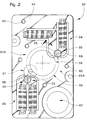
- FIG. 2 Using FIG. 2, a first mode will be described production of an electromechanical device according to the invention.
- the electromechanical device 52 comprises a plate base or plate 54 made of soft magnetic material used to jointly form the respective stators of two 2A and 2B two-phase electromechanical transducers, all two similar to the transducer described above using of figure 1. These transducers 2A and 2B will not be described again here in detail.
- the 24A magnetic stator pole common to both transducers 2A and 2B form the stator magnetic pole of each of these two transducers which surround, in projection in the general plane of the plate 54, the stator magnetic poles 22 and 23 of each of these two transducers which have been described previously.
- the 24A common stator magnetic pole is therefore used for closure of the magnetic fluxes of the two 2A transducers and 2B which are magnetically decoupled one of the other.
- the plate 54 can be used as a stator plate for a plurality of two-phase electromechanical transducers according to the invention.
- the layout of each transducer in the surface defined by the plate 54 is free and determined by the device manufacturer electromechanical according to the invention.
- Plate 54 is used for assembly, at least partially, of several elements, including mobiles 57, 58 and 59. Mobiles 57 and 59 are respectively mechanically coupled to the rotors respective 6A and 6B of the two transducers 2A and 2B.
- the plate 54 comprises construction holes 60, threaded or not, used for mounting of various elements.
- the plate 54 has a recess (or a recess) to accommodate a supply battery for transducers 2A and 2B given that in the case described here they are used as motor for driving mobiles 57, 58 and 59.
- the rotors 6A and 6B are mounted head to tail, that is to say where they are mounted in directions of construction opposite each other. So according to a construction similar to that described in the document EP 0 393 606, the two transducers drive two needles mounted coaxially to each other.
- the electromechanical device 72 comprises a base plate or base plate 74 formed of a material magnetic.
- This base plate 74 forms the stators respective of two electromechanical transducers two-phase 2C and 2D construction equivalent to transducer described above using figure 1.
- the two rotors 6C and 6D of the two respective transducers are mechanically coupled to two coaxial mobiles 76 and arranged on either side of the plate 74.
- a opening 78 is provided in plate 74 to accommodate it a power stack. 2C two-phase transducers and 2D will not be described again here in detail.
- This second embodiment of a device electromechanical essentially differs from the first embodiment described using FIG. 2 in that that the two two-phase transducers 2C and 2D have their coils 18A, 20A, 18B and 20B located, projected in the general plane of the plate 74 forming a stator, at the interior of a single stator opening 80 whose edge 82 is closed on itself.
- the magnetic pole stator 84 which is used to close the magnetic flux propagating in any of the four nuclei surrounded by the four coils respectively mentioned above is a magnetic pole common to both 2C and 2D transducers.
- the plate 74 serves as stator common to the two two-phase transducers 2C and 2D as in the case of the first embodiment described in Figure 2.
- the present invention is not limited to the modes of realization described above, the skilled person being able without providing other construction variants and arrangement of transducers according to constraints for the construction of electromechanical devices.
- the cores carrying the coils can be curved.
- electromechanical devices described in figures 2 and 3 form indicators analog used to display the value of at least one variable determined.
- the displayed variable by these electromechanical devices is time.
Landscapes
- Engineering & Computer Science (AREA)
- Power Engineering (AREA)
- Electromechanical Clocks (AREA)
Abstract
Description
- un stator en matériau magnétique;
- un rotor comprenant un aimant permanent;
- deux bobines;
- la figure 1 représente schématiquement une vue de dessus du transducteur électromécanique biphasé selon l'invention;
- la figure 2 est une vue de dessus d'un premier mode de réalisation d'un dispositif électromécanique selon l'invention, et
- la figure 3 est une vue de dessus schématique d'un deuxième mode de réalisation d'un dispositif électromécanique selon l'invention.
Claims (10)
- Transducteur électromécanique biphasé (2) comprenant :ledit stator comprenant une structure plane (12) et des premier et deuxième noyaux (14, 16) autour desquels sont respectivement montées lesdites deux bobines, ladite structure plane définissant des premier, deuxième et troisième pôles magnétiques statoriques (22, 23, 24) dont les trois épanouissements polaires (26, 27, 28) respectifs définissent un trou (30) traversé par ledit rotor dont ledit aimant permanent est couplé magnétiquement auxdits trois épanouissements polaires, lesdits premier et deuxième noyaux reliant respectivement lesdits premier et deuxième pôles magnétiques statoriques (22, 23) audit troisième pôle magnétique statorique (24), ce transducteur étant caractérisé en ce que lesdites deux bobines sont situées à l'intérieur d'une ouverture statorique (48) prévue dans ladite structure plane relativement à une projection dans le plan général de cette structure plane, le bord (50) de ladite ouverture statorique étant fermé sur lui-même.un stator (4) en matériau magnétique;un rotor (6) comprenant un aimant permanent (8);deux bobines (18, 20);
- Transducteur électromécanique selon la revendication 1, caractérisé en ce que la partie de ladite structure plane (12) définissant ledit troisième pôle magnétique statorique (24) entoure, en projection dans ledit plan général de cette structure plane, l'ensemble formé par deux parties de cette structure plane définissant respectivement lesdits premier et deuxième pôles magnétiques statoriques (22, 23) et par lesdites deux bobines (18, 20).
- Transducteur électromécanique selon la revendication 2, caractérisé en ce que ledit trou (30) traversé par ledit rotor (6) a un bord fermé sur lui-même, ce trou et ladite ouverture statorique définissant des isthmes (32, 33, 34) de haute réluctance isolant magnétiquement lesdits pôles magnétiques statoriques (22, 23, 24), ladite structure plane (12) étant constituée par une seule et même pièce.
- Transducteur électromécanique (2A; 2B) selon l'une des revendications précédentes, caractérisé en ce que ledit stator définit une plaque de base ou une platine (54) sur laquelle sont montés au moins partiellement des éléments (57, 58, 59) d'un dispositif électromécanique (52) dont au moins un desdits éléments est couplé mécaniquement audit rotor (6A; 6B) dudit transducteur électromécanique.
- Dispositif électromécanique (52; 72) comprenant une pluralité de transducteurs électromécaniques (2A, 2B; 2C, 2D) dont la pluralité de stators respectifs sont formés partiellement par une structure plane commune (54; 74) définissant une pluralité de trous traversés respectivement par une pluralité de rotors (6A, 6B; 6C, 6D) de ladite pluralité de transducteurs, ce dispositif électromécanique étant caractérisé en ce qu'au moins un de ladite pluralité de transducteurs est selon l'une des revendications 1 à 3.
- Dispositif électromécanique selon la revendication 5, caractérisé en ce que ladite structure plane commune (54; 74) sert de plaque de base ou de platine sur laquelle sont montés au moins partiellement des éléments (57, 58, 59; 76) de ce dispositif électromécanique.
- Dispositif électromécanique (72) selon la revendication 5, caractérisé en ce que chaque rotor (6A, 6B; 6C, 6D) de ladite pluralité de rotors est couplé mécaniquement à un desdits éléments dudit dispositif électromécanique.
- Dispositif électromécanique (72) selon l'une des revendications 5 à 7, caractérisé en ce qu'au moins deux (2C, 2D) desdits transducteurs sont selon l'une des revendications 1 à 3, les noyaux de ces deux transducteurs et les bobines respectives (18A, 20A, 18B, 20B) qui les entourent étant agencés dans une seule et même ouverture (80) de ladite structure plane (74) commune à ces deux transducteurs.
- Dispositif électromécanique selon l'une des revendications précédentes, caractérisé en ce que ce dispositif forme un indicateur analogique servant à afficher la valeur d'au moins une variable déterminée.
- Dispositif électromécanique selon la revendication 9, caractérisé en ce qu'il forme le mouvement d'une pièce d'horlogerie, ladite au moins une variable affichée étant le temps.
Priority Applications (2)
| Application Number | Priority Date | Filing Date | Title |
|---|---|---|---|
| EP19960119434 EP0847130B1 (fr) | 1996-12-04 | 1996-12-04 | Transducteur électromécanique biphasé et dispositif électromécanique comprenant au moins un tel transducteur |
| DE69626831T DE69626831T2 (de) | 1996-12-04 | 1996-12-04 | Zweiphasen elektromechanischer Wandler und elektromechanischer Einrichtung mit wenigstens einem solchen Wandler |
Applications Claiming Priority (1)
| Application Number | Priority Date | Filing Date | Title |
|---|---|---|---|
| EP19960119434 EP0847130B1 (fr) | 1996-12-04 | 1996-12-04 | Transducteur électromécanique biphasé et dispositif électromécanique comprenant au moins un tel transducteur |
Publications (2)
| Publication Number | Publication Date |
|---|---|
| EP0847130A1 true EP0847130A1 (fr) | 1998-06-10 |
| EP0847130B1 EP0847130B1 (fr) | 2003-03-19 |
Family
ID=8223466
Family Applications (1)
| Application Number | Title | Priority Date | Filing Date |
|---|---|---|---|
| EP19960119434 Expired - Lifetime EP0847130B1 (fr) | 1996-12-04 | 1996-12-04 | Transducteur électromécanique biphasé et dispositif électromécanique comprenant au moins un tel transducteur |
Country Status (2)
| Country | Link |
|---|---|
| EP (1) | EP0847130B1 (fr) |
| DE (1) | DE69626831T2 (fr) |
Cited By (1)
| Publication number | Priority date | Publication date | Assignee | Title |
|---|---|---|---|---|
| EP2813904A1 (fr) * | 2013-06-10 | 2014-12-17 | ETA SA Manufacture Horlogère Suisse | Mouvement électronique comprenant un moteur horloger |
Citations (3)
| Publication number | Priority date | Publication date | Assignee | Title |
|---|---|---|---|---|
| JPS5615154A (en) * | 1979-07-13 | 1981-02-13 | Rhythm Watch Co Ltd | Miniature motor for timepiece |
| EP0393606A1 (fr) | 1989-04-21 | 1990-10-24 | Eta SA Fabriques d'Ebauches | Pièce d'horlogerie électronique à affichage analogique |
| EP0698957A1 (fr) * | 1994-08-26 | 1996-02-28 | Eta SA Fabriques d'Ebauches | Transducteur électromécanique comportant deux rotors |
-
1996
- 1996-12-04 EP EP19960119434 patent/EP0847130B1/fr not_active Expired - Lifetime
- 1996-12-04 DE DE69626831T patent/DE69626831T2/de not_active Expired - Lifetime
Patent Citations (3)
| Publication number | Priority date | Publication date | Assignee | Title |
|---|---|---|---|---|
| JPS5615154A (en) * | 1979-07-13 | 1981-02-13 | Rhythm Watch Co Ltd | Miniature motor for timepiece |
| EP0393606A1 (fr) | 1989-04-21 | 1990-10-24 | Eta SA Fabriques d'Ebauches | Pièce d'horlogerie électronique à affichage analogique |
| EP0698957A1 (fr) * | 1994-08-26 | 1996-02-28 | Eta SA Fabriques d'Ebauches | Transducteur électromécanique comportant deux rotors |
Non-Patent Citations (1)
| Title |
|---|
| PATENT ABSTRACTS OF JAPAN vol. 005, no. 066 (E - 055) 2 May 1981 (1981-05-02) * |
Cited By (4)
| Publication number | Priority date | Publication date | Assignee | Title |
|---|---|---|---|---|
| EP2813904A1 (fr) * | 2013-06-10 | 2014-12-17 | ETA SA Manufacture Horlogère Suisse | Mouvement électronique comprenant un moteur horloger |
| CN104242754A (zh) * | 2013-06-10 | 2014-12-24 | Eta瑞士钟表制造股份有限公司 | 包括用于钟表的马达的电子机芯 |
| US9146539B2 (en) | 2013-06-10 | 2015-09-29 | Eta Sa Manufacture Horlogere Suisse | Electronic movement including a motor for a timepiece |
| CN104242754B (zh) * | 2013-06-10 | 2017-07-14 | Eta瑞士钟表制造股份有限公司 | 包括用于钟表的马达的电子机芯 |
Also Published As
| Publication number | Publication date |
|---|---|
| DE69626831D1 (de) | 2003-04-24 |
| EP0847130B1 (fr) | 2003-03-19 |
| DE69626831T2 (de) | 2004-03-04 |
Similar Documents
| Publication | Publication Date | Title |
|---|---|---|
| FR2754953A1 (fr) | Moteur polyphase, notamment pour l'entrainement d'une aiguille d'un afficheur | |
| EP0811269B1 (fr) | Moteur diphase, notamment un moteur d'horlogerie ou un moteur pour l'entrainement d'une aiguille d'un afficheur | |
| EP0625738B1 (fr) | Alarme silencieuse électromagnétique | |
| EP0143227B1 (fr) | Moteur électromagnétique pas à pas à deux rotors couplés | |
| EP0509351B1 (fr) | Moteur électromagnétique à deux sens de rotation, notamment pour pièce d'horlogerie | |
| EP0393605B1 (fr) | Pièce d'horlogerie comportant au moins deux moteurs | |
| CH690882A5 (fr) | Transducteur électromécanique biphasé et dispositif électromécanique comprenant au moins un tel transducteur. | |
| EP0547534B1 (fr) | Transducteur électromagnétique à aimant permanent multipolaire | |
| EP2169479B1 (fr) | Dispositif base de temps pour une montre | |
| EP0847130B1 (fr) | Transducteur électromécanique biphasé et dispositif électromécanique comprenant au moins un tel transducteur | |
| EP0589342B1 (fr) | Transducteur électromagnétique polyphasé à aimant permanent multipolaire | |
| EP0525462A1 (fr) | Transducteur électromagnétique polyphasé à aimant permanent, notamment moteur d'entraînement | |
| CH690881A5 (fr) | Transducteur électromécanique monophasé et dispositif électromécanique comprenant au moins un tel transducteur. | |
| EP0698957B1 (fr) | Transducteur électromécanique comportant deux rotors | |
| EP0848480B1 (fr) | Transducteur électromécanique monophasé, en particulier du type horloger, et dispositif électromécanique comprenant au moins un tel transducteur | |
| EP1890204B1 (fr) | Montre électronique comprenant un résonateur | |
| EP0472061B1 (fr) | Pièce d'horlogerie du type électromécanique | |
| EP0661794B1 (fr) | Transducteur électromécanique cylindrique | |
| EP0790540A1 (fr) | Transducteur électromécanique à aimants permanents multipolaires | |
| WO2006006037A1 (fr) | Affichage analogique d’un mouvement horloger | |
| EP1729188A1 (fr) | Moteur de petites dimensions, notamment du type horloger | |
| EP0101410A2 (fr) | Montre électro-mécanique munie d'un écran magnétique | |
| EP0718960B1 (fr) | Moteur pas à pas multipolaire polyphasé | |
| EP3211489A1 (fr) | Module moteur simplifie | |
| EP0924838A1 (fr) | Générateur d'énergie électrique monophasé |
Legal Events
| Date | Code | Title | Description |
|---|---|---|---|
| PUAI | Public reference made under article 153(3) epc to a published international application that has entered the european phase |
Free format text: ORIGINAL CODE: 0009012 |
|
| AK | Designated contracting states |
Kind code of ref document: A1 Designated state(s): DE FR GB NL SE |
|
| 17P | Request for examination filed |
Effective date: 19981210 |
|
| AKX | Designation fees paid |
Free format text: DE FR GB NL SE |
|
| RBV | Designated contracting states (corrected) |
Designated state(s): DE FR GB NL SE |
|
| 17Q | First examination report despatched |
Effective date: 20010410 |
|
| GRAH | Despatch of communication of intention to grant a patent |
Free format text: ORIGINAL CODE: EPIDOS IGRA |
|
| GRAH | Despatch of communication of intention to grant a patent |
Free format text: ORIGINAL CODE: EPIDOS IGRA |
|
| GRAA | (expected) grant |
Free format text: ORIGINAL CODE: 0009210 |
|
| AK | Designated contracting states |
Designated state(s): DE FR GB NL SE |
|
| PG25 | Lapsed in a contracting state [announced via postgrant information from national office to epo] |
Ref country code: NL Free format text: LAPSE BECAUSE OF FAILURE TO SUBMIT A TRANSLATION OF THE DESCRIPTION OR TO PAY THE FEE WITHIN THE PRESCRIBED TIME-LIMIT Effective date: 20030319 Ref country code: GB Free format text: LAPSE BECAUSE OF FAILURE TO SUBMIT A TRANSLATION OF THE DESCRIPTION OR TO PAY THE FEE WITHIN THE PRESCRIBED TIME-LIMIT Effective date: 20030319 |
|
| RAP1 | Party data changed (applicant data changed or rights of an application transferred) |
Owner name: ETA SA MANUFACTURE HORLOGERE SUISSE |
|
| REG | Reference to a national code |
Ref country code: GB Ref legal event code: FG4D Free format text: NOT ENGLISH |
|
| REF | Corresponds to: |
Ref document number: 69626831 Country of ref document: DE Date of ref document: 20030424 Kind code of ref document: P |
|
| PG25 | Lapsed in a contracting state [announced via postgrant information from national office to epo] |
Ref country code: SE Free format text: LAPSE BECAUSE OF FAILURE TO SUBMIT A TRANSLATION OF THE DESCRIPTION OR TO PAY THE FEE WITHIN THE PRESCRIBED TIME-LIMIT Effective date: 20030619 |
|
| NLV1 | Nl: lapsed or annulled due to failure to fulfill the requirements of art. 29p and 29m of the patents act | ||
| GBV | Gb: ep patent (uk) treated as always having been void in accordance with gb section 77(7)/1977 [no translation filed] |
Effective date: 20030319 |
|
| PLBE | No opposition filed within time limit |
Free format text: ORIGINAL CODE: 0009261 |
|
| STAA | Information on the status of an ep patent application or granted ep patent |
Free format text: STATUS: NO OPPOSITION FILED WITHIN TIME LIMIT |
|
| 26N | No opposition filed |
Effective date: 20031222 |
|
| PGFP | Annual fee paid to national office [announced via postgrant information from national office to epo] |
Ref country code: DE Payment date: 20101208 Year of fee payment: 15 |
|
| PGFP | Annual fee paid to national office [announced via postgrant information from national office to epo] |
Ref country code: FR Payment date: 20120119 Year of fee payment: 16 |
|
| REG | Reference to a national code |
Ref country code: FR Ref legal event code: ST Effective date: 20130830 |
|
| REG | Reference to a national code |
Ref country code: DE Ref legal event code: R119 Ref document number: 69626831 Country of ref document: DE Effective date: 20130702 |
|
| PG25 | Lapsed in a contracting state [announced via postgrant information from national office to epo] |
Ref country code: DE Free format text: LAPSE BECAUSE OF NON-PAYMENT OF DUE FEES Effective date: 20130702 |
|
| PG25 | Lapsed in a contracting state [announced via postgrant information from national office to epo] |
Ref country code: FR Free format text: LAPSE BECAUSE OF NON-PAYMENT OF DUE FEES Effective date: 20130102 |