EP0847160A2 - Système pour la transmission dirigée point à multipoint d'information - Google Patents
Système pour la transmission dirigée point à multipoint d'information Download PDFInfo
- Publication number
- EP0847160A2 EP0847160A2 EP97440124A EP97440124A EP0847160A2 EP 0847160 A2 EP0847160 A2 EP 0847160A2 EP 97440124 A EP97440124 A EP 97440124A EP 97440124 A EP97440124 A EP 97440124A EP 0847160 A2 EP0847160 A2 EP 0847160A2
- Authority
- EP
- European Patent Office
- Prior art keywords
- signals
- transmission line
- switch
- detector
- transmission lines
- Prior art date
- Legal status (The legal status is an assumption and is not a legal conclusion. Google has not performed a legal analysis and makes no representation as to the accuracy of the status listed.)
- Granted
Links
- 230000005540 biological transmission Effects 0.000 title claims abstract description 150
- 230000008878 coupling Effects 0.000 claims description 31
- 238000010168 coupling process Methods 0.000 claims description 31
- 238000005859 coupling reaction Methods 0.000 claims description 31
- 230000002457 bidirectional effect Effects 0.000 claims description 5
- 230000008054 signal transmission Effects 0.000 claims description 2
- 230000007257 malfunction Effects 0.000 description 6
- 238000001514 detection method Methods 0.000 description 4
- 230000007547 defect Effects 0.000 description 2
- 230000003287 optical effect Effects 0.000 description 2
- 230000003321 amplification Effects 0.000 description 1
- 239000003795 chemical substances by application Substances 0.000 description 1
- 230000000694 effects Effects 0.000 description 1
- 239000000835 fiber Substances 0.000 description 1
- 238000009434 installation Methods 0.000 description 1
- 238000012544 monitoring process Methods 0.000 description 1
- 238000003199 nucleic acid amplification method Methods 0.000 description 1
- 230000002787 reinforcement Effects 0.000 description 1
- 238000011144 upstream manufacturing Methods 0.000 description 1
Images


Classifications
-
- H—ELECTRICITY
- H04—ELECTRIC COMMUNICATION TECHNIQUE
- H04L—TRANSMISSION OF DIGITAL INFORMATION, e.g. TELEGRAPHIC COMMUNICATION
- H04L12/00—Data switching networks
- H04L12/28—Data switching networks characterised by path configuration, e.g. LAN [Local Area Networks] or WAN [Wide Area Networks]
- H04L12/42—Loop networks
-
- H—ELECTRICITY
- H04—ELECTRIC COMMUNICATION TECHNIQUE
- H04L—TRANSMISSION OF DIGITAL INFORMATION, e.g. TELEGRAPHIC COMMUNICATION
- H04L12/00—Data switching networks
- H04L12/28—Data switching networks characterised by path configuration, e.g. LAN [Local Area Networks] or WAN [Wide Area Networks]
- H04L12/42—Loop networks
- H04L12/437—Ring fault isolation or reconfiguration
Definitions
- the invention relates to a directed point-to-multipoint system Information transmission in a ring-shaped distribution network with one Control center into which the information to be transmitted is fed and in at least two outgoing in different directions Transmission lines in the form of signals is passed, wherein at least one receiving device is provided, which signals receives at least one of the transmission lines.
- Such a system is for example from the company magazine "telecom report “from Siemens AG, issue 3/1996, pages 10 to 13.
- signals are usually from one Central via optical splitter and fiber optic lines as well as optical Transfer the amplifier in a tree shape to several receiving devices.
- Such network structures are e.g. B. in the company magazine “Electrical sympaenectomy “by Alcatel SEL, Stuttgart, 3rd quarter 1993, pages 248 to 259.
- each receiving device at least two supply lines from the head office, at least a switch and at least two detectors for monitoring the incoming signals are required.
- the object of the present invention is to provide a system with to improve the features mentioned in that at same function and the same error security a considerable Simplification, especially a reduction in the minimum required Components is effected.
- this task is as simple as effective way solved that the at least two Transmission lines converge in a circuit structure that out at least one of the transmission lines between the control center and Switch structure the signals coming from the control center as well as those from Circuitry coming signals partially or completely decoupled and via a combiner or a switch of at least one receiving device are fed, and that in the switching structure those transmission lines coming from the central office on which at least one receiving device is coupled, a detector is provided which in the absence of a signal on the corresponding transmission line operated a switch, which the Signals from another transmission line coming from the control center redirected to a transmission line to which all those receiving devices are coupled, which also to the corresponding from Detector monitored transmission line are coupled.
- An embodiment of the invention is particularly simple Systems in which, in the event of a fault, the switching structure is different from the Signals coming to the corresponding transmission line Detector supervised transmission line redirects.
- An embodiment of the invention is particularly preferred System in which at least one further transmission line is provided are that go in different directions from the switching structure, and on each of which is coupled to at least one receiving device.
- a special performance gain is achieved because pro signal-carrying transmission line in contrast to the one above described simple case only one coupling device per Receiving unit is required, which can also be unidirectional. In order to there are significantly lower attenuation losses per Transmission line.
- Another advantage of this preferred embodiment is that a clear signal direction can be specified. This is an active one Signal amplification in the transmission lines easier too accomplish.
- Amplifiers can be operated in a de-energized stand-by mode.
- the system according to the invention provides that at least one Receiving device two coupling devices for signal coupling out one or two transmission lines are provided, the first Coupling device decouples incoming signals from the control center and passes on to a detector which, when signals are present, a switch closes and the signals via the switch to the receiving device passes on, and wherein the second coupling device from the switching structure decouples incoming signals, but only then via the switch in the Receiving device to be passed if the detector is none Signals from the first coupling device are detected.
- a preferred direction of the incoming signals is thus the shortest Established routes from the headquarters, so that the transmission routes in error-free cases are optimally short.
- this embodiment lower attenuation losses in the signals because the switch for forwarding the signals to the receiving device in Pass mode generally works essentially undamped, while, for example, a combiner to bring the two together Signal paths in front of the receiving device an attenuation of the signal from approx. 3 dB.
- a combiner for at least one receiving device Merging of the decoupled coming from the head office Signals with the decoupled signals coming from the switch assembly be provided.
- Such a combiner is significant as a component easier and cheaper than a switch with an upstream detector.
- the two signals from only one transmission line tapped.
- a switching structure is also included switched forwarding of received signals, at least two signal transmission lines open into the circuit structure, and where a detector on at least one confluent transmission line is provided, which is in the absence of a signal on the corresponding Transmission line operated a switch, which the signals another transmission line to the one monitored by the detector Transmission line and / or redirected to a third transmission line.
- Such a circuit structure is preferably used in a system of the type mentioned above.
- Switching structure is provided that exactly three transmission lines in the switching structure open, with each confluent Transmission line a detector is provided, which is not present a signal on the corresponding transmission line a switch actuates which signals of another transmission line on the from corresponding detector monitors redirected transmission line.
- a somewhat more comfortable, alternative embodiment is emerging characterized by the fact that four transmission lines open into the switch assembly, one on two of the merging transmission lines Detector is provided, which in the absence of a signal on the corresponding overtreatment line actuates a switch which switches the signals the other transmission line monitored by a detector to one of the transmission lines not monitored by a detector redirects.
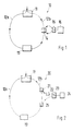
- the system 10 shown schematically in FIG. 1 for the directed point-to-multipoint Information transmission has a ring-shaped distribution network a control center 11, into which the information to be transmitted is fed and in two transmission lines going in different directions 12a, 12b is forwarded in the form of signals.
- the two Transmission lines 12a, 12b run in a switching arrangement 13 together. From the transmission line 12b by means of a bidirectional coupling device 14 both in the direction from the center 11 on the switching structure 13 as well as in the opposite direction current signals partially decoupled in a combiner 15 merged and fed to a receiving device 16.
- the transmission line 12b ends in Switch structure 13 blind, so that in the bidirectional coupling device 14th only signals arriving from the control center 11 and the Receiving device 16 are supplied.
- the transmission line 12b runs over a connection in FIG. 1 detector, not shown, which in the absence of a signal on the Transmission line 12b also not shown in FIG. 1 Switch actuated, the second also running in the switching structure Transmission line 12a connects to the transmission line 12b.
- the receiver 16 via the coupling device 14 and the Combiner 15 loaded with signals from the transmission line 12a, in the event of a malfunction due to an interruption in the transmission line 12b the route between the control center 11 and the coupling device 14 has taken place.
- FIG. 2 shows an embodiment improved over FIG. 1, namely a system 20 in which on the transmission line 12b that from the switch 11 coming signals by means of a unidirectional coupling device 21 coupled out and fed to a switch 23 via a detector 22 will. If the detector 22 detects the presence of signals, causes he switch 23 for switching through to a receiver 24. Otherwise, the switch 23 connects the receiver 24 to one another unidirectional coupling device 25, the signals from the Taps transmission line 12, which come from the switch 13.
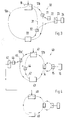
- FIG. 3 schematically shows a further improvement compared to FIG. 2 Embodiment shown, in which a system 30 additionally one has further transmission line 31 in the form of a half ring.
- a system 30 additionally one has further transmission line 31 in the form of a half ring.
- the signal coming from the switch assembly 33 is trapped by means of a unidirectional coupling device 32 from the transmission line 31 uncoupled and fed to the switch 23.
- the exact way it works the switching structure 33 is shown in FIG. 7.
- the system 40 which is shown schematically in FIG. 4, consists of a cascade of two ring-shaped distribution networks. On the right side of the first distribution network shown in the upper half of the figure is via a Transmission line 12b a receiver 16 with signals from the central office 41 loaded. On the left is parallel to the transmission line 12a ', which runs from the control center 41 to a switch assembly 43, another Transmission line 42 is provided to the signals from the switching structure 43 placed and by means of a coupling device 44 on a switch 47 can be coupled out.
- the switch is in the normal operating state 47 on the basis of a corresponding good signal from a detector 46 switched through that he is a connection between a coupling device 45, the signals coming from the control center 41 from the transmission line 12a 'decouples with one instead of a receiver provided provided further center 48.
- the other central 48 is again the starting point of another ring-shaped distribution network a further switching structure 49. This is particularly advantageous if if longer distances between the first and the second distribution network to be overcome.
- the system 50 shown in FIG. 5 differs from that previously described systems in that a double ring structure and so that a significantly greater redundancy is provided.
- a headquarters 51 is with two transmission lines that form an outer ring a switching structure 53 connected.
- go from the switch assembly 53 shown in the figure further transmission lines from the one form inner ring.
- each from an associated detector 55a to 55d are monitored. If the Detectors 55a to 55d detect the presence of signals, switch the corresponding switch 54a to 54d so that the respective receivers 52a to 52d with the associated coupling device 56a to 56d is connected.
- one of the detectors 55a to 55d detects a malfunction, it causes the associated switch 54a or 54b or 54c or 54d for switching through to a coupling device 57a or 57b or 57c or 57d, each of which is a signal coming from the switch assembly 53 taps inner ring.
- a coupling device 57a or 57b or 57c or 57d each of which is a signal coming from the switch assembly 53 taps inner ring.
- FIG. 6 schematically shows a particularly simple embodiment of a Switching structure 60 according to the invention, for example in the systems 10, 20 according to Figures 1 and 2 can be used.
- the Switch structure 60 open two transmission lines 61a, 61b, the for example signals from a control center, not shown in FIG Transport switch assembly 60. If one provided in the switching structure 60 Detector 62 the absence of a signal on the transmission line 61b detects, he switches a switch 63, so that signals from the Transmission line 61a are routed to the transmission line 61b.
- the switching structure according to FIG Fig. 6 can also be expanded so that between the incoming transmission line 61a and switch 63 another Detector is provided that the proper presence of signals monitored on the transmission line 61a and accordingly likewise controls the switch 63.
- Fig. 7 shows a switch 70 according to the invention, which in Single ring systems with an additional half ring can be used, such as they are shown for example in Figures 3 and 4.
- the switch 70 open transmission lines 71a and 71b, which in normal Introduce operating state signals into switch 70.
- one Transmission line 71c provided in the above-described embodiments a half ring with outgoing from the switch assembly 70 Can feed signals.
- the transmission lines 71a to 71c are passed through Detectors 72a to 72c each for the presence of incoming Signals monitored.
- a switch 73 shown which has three inputs, one at each input Connection line to one of the three detectors 72a to 72c and thus to each of the transmission lines 71a to 71c opens.
- the switch 73 In normal Operating state is the switch 73 in a position in which none Connection between its three inputs is established, that is, on Signals arriving on the transmission lines 71a to 71c end blind in switch 73.
- detector 72a detects the absence of a signal the line 71a detects, it causes the switch 73, in a Switch position to go, in which the transmission line 71b with the Transmission line 71a is connected. If the detector 72b does No signal from the incoming transmission line 71b detects, it will cause the switch 73 to a switch position go where the transmission line 71a with the transmission line 71c is connected, which acts as a replacement line for those on the Transmission line 71b coupled receiver and one for Transmission line 71b forms a parallel half ring. Thereby are coupled to the transmission lines 71b and 71c Receiver now with signals over the transmission line 71c provided.
- FIG. 8 shows a switching structure 80 according to the invention, which is suitable for use in a double ring system, for example in Fig. 5 is shown.
- Two transmission lines 81a, 81b which feed signals to the switch assembly 80. Also go from Switching structure 80 transmission lines 81c, 81d, which signals from Guide switch assembly 80 away. The transmission lines 81a and 81b are checked for the presence by a detector 82a or 82b monitored by signals.
- detector 82a If detector 82a detects the absence of a signal on the Transmission line 81a, it causes a switch 83a, one Connection between the signal-carrying transmission line 81b with the establish signal-carrying transmission line 81c. Controls as well detector 82b, which monitors transmission line 81b, at Detection of a fault, the switch 83b so that this one Connection between the signal-carrying transmission line 81a with the signal-producing transmission line 81d.
Landscapes
- Engineering & Computer Science (AREA)
- Computer Networks & Wireless Communication (AREA)
- Signal Processing (AREA)
- Small-Scale Networks (AREA)
Applications Claiming Priority (2)
| Application Number | Priority Date | Filing Date | Title |
|---|---|---|---|
| DE1996150088 DE19650088A1 (de) | 1996-12-03 | 1996-12-03 | System zur gerichteten Punkt-zu-Mehrpunkt Informationsübertragung |
| DE19650088 | 1996-12-03 |
Publications (3)
| Publication Number | Publication Date |
|---|---|
| EP0847160A2 true EP0847160A2 (fr) | 1998-06-10 |
| EP0847160A3 EP0847160A3 (fr) | 2004-12-01 |
| EP0847160B1 EP0847160B1 (fr) | 2005-10-12 |
Family
ID=7813493
Family Applications (1)
| Application Number | Title | Priority Date | Filing Date |
|---|---|---|---|
| EP19970440124 Expired - Lifetime EP0847160B1 (fr) | 1996-12-03 | 1997-12-03 | Système pour la transmission dirigée point à multipoint d'information |
Country Status (3)
| Country | Link |
|---|---|
| EP (1) | EP0847160B1 (fr) |
| DE (2) | DE19650088A1 (fr) |
| ES (1) | ES2248835T3 (fr) |
Cited By (3)
| Publication number | Priority date | Publication date | Assignee | Title |
|---|---|---|---|---|
| US6469981B1 (en) | 1998-07-16 | 2002-10-22 | Alcatel | Point-to-multipoint network |
| US6643255B1 (en) | 1998-07-16 | 2003-11-04 | Alcatel | Node of a point-to-multipoint network |
| EP1331748A3 (fr) * | 2002-01-24 | 2008-12-17 | Alcatel Lucent | Méthode de sécurisation d'un réseau de télécommunication optique en anneau ainsi que noeud de communication à amplification et concentrateur de trafic |
Families Citing this family (1)
| Publication number | Priority date | Publication date | Assignee | Title |
|---|---|---|---|---|
| DE19922171B4 (de) * | 1999-05-12 | 2009-08-27 | Infineon Technologies Ag | Kommunikationssystem mit einem Kommunikationsbus |
Family Cites Families (5)
| Publication number | Priority date | Publication date | Assignee | Title |
|---|---|---|---|---|
| US4009469A (en) * | 1975-12-19 | 1977-02-22 | Ibm Corporation | Loop communications system with method and apparatus for switch to secondary loop |
| DE3634019A1 (de) * | 1986-10-06 | 1988-04-14 | Man Technologie Gmbh | Vorrichtung und verfahren zum seriellen datenaustausch zwischen mehr als zwei teilnehmern |
| DE4002022A1 (de) * | 1990-01-24 | 1991-07-25 | Siemens Ag | Verfahren und anordnung zur hochverfuegbaren uebertragung von daten |
| AU1234092A (en) * | 1990-12-17 | 1992-07-22 | Aster Corporation | Optical communication monitoring and control |
| US5539564A (en) * | 1993-09-22 | 1996-07-23 | Nippon Telegraph And Telephone Corporation | Point-to-multipoint optical transmission system |
-
1996
- 1996-12-03 DE DE1996150088 patent/DE19650088A1/de not_active Withdrawn
-
1997
- 1997-12-03 EP EP19970440124 patent/EP0847160B1/fr not_active Expired - Lifetime
- 1997-12-03 DE DE59712442T patent/DE59712442D1/de not_active Expired - Lifetime
- 1997-12-03 ES ES97440124T patent/ES2248835T3/es not_active Expired - Lifetime
Cited By (4)
| Publication number | Priority date | Publication date | Assignee | Title |
|---|---|---|---|---|
| US6469981B1 (en) | 1998-07-16 | 2002-10-22 | Alcatel | Point-to-multipoint network |
| US6643255B1 (en) | 1998-07-16 | 2003-11-04 | Alcatel | Node of a point-to-multipoint network |
| EP0973288A3 (fr) * | 1998-07-16 | 2004-11-17 | Alcatel | Noeud d'interconnection pour un réseau de transmission par câble |
| EP1331748A3 (fr) * | 2002-01-24 | 2008-12-17 | Alcatel Lucent | Méthode de sécurisation d'un réseau de télécommunication optique en anneau ainsi que noeud de communication à amplification et concentrateur de trafic |
Also Published As
| Publication number | Publication date |
|---|---|
| DE19650088A1 (de) | 1998-06-04 |
| EP0847160B1 (fr) | 2005-10-12 |
| EP0847160A3 (fr) | 2004-12-01 |
| ES2248835T3 (es) | 2006-03-16 |
| DE59712442D1 (de) | 2006-02-23 |
Similar Documents
| Publication | Publication Date | Title |
|---|---|---|
| DE69634611T2 (de) | Selbstheilendes netzwerk | |
| DE69831679T2 (de) | Verfahren und system zur verbindung von ringnetzen | |
| DE69531594T2 (de) | Kommunikationsnetzwerk mit Ringstruktur über einen optischen Träger und rekonfigurierbarer Knoten für diese Struktur | |
| DE69513663T2 (de) | Atm-koppelfeld mit doppeltem vermittlungsebenenbetrieb | |
| DE2645778C2 (de) | Nachrichtenübertragungsanlage mit einer Primärschleife und einer Sekundärschleife | |
| DE69622123T2 (de) | Koppelanordnung zum Koppeln von optischen Verbindungen | |
| DE3140058C2 (fr) | ||
| DE69722981T2 (de) | Knoten eines optischen Übertragungsnetzes und Verfahren zur Übertragungsaufrechterhaltung nach einer Netzstörung | |
| DE68920459T2 (de) | Umschaltungseinrichtung für Übertragungsleitungen. | |
| DE4090614C2 (de) | Netzwerk vom Doppelbustyp | |
| EP0175120B2 (fr) | Dispositif de protection pour un réseau électrique | |
| EP0973288B1 (fr) | Noeud d'interconnection pour un réseau de transmission par câble | |
| EP0847160B1 (fr) | Système pour la transmission dirigée point à multipoint d'information | |
| EP1097540B1 (fr) | Procede et dispositif pour optimiser la securite de transmission et la tolerance aux defauts dans des reseaux de donnees a debit binaire eleve | |
| EP1425872B1 (fr) | Procédé et système de communication permettant d'établir au moins une liaison de communication à securité integrée | |
| EP0923244A2 (fr) | Amplificateur intermédiaire pour un réseau de communication pour la réception et la retransmission de signaux multiplexés par répartition en fréquence | |
| EP1016238A1 (fr) | Systeme de redondance "1:n" et "1:1" pour systeme asn | |
| DE68917534T2 (de) | Datenpfadschutz. | |
| EP0532787A1 (fr) | Dispositif pour l'opération de détecteurs de dangers | |
| DE19831954A1 (de) | Punkt-zu-Mehrpunkt Netzwerk | |
| DE1924644A1 (de) | Schaltsystem fuer Mikrowellen-Leistungsverstaerker | |
| DE10343615A1 (de) | Netzknoten für ein optisches Nachrichtenübertragungsnetz | |
| DE19844185C2 (de) | Busleitungssystem | |
| DE102016207857B4 (de) | Verfahren zur effizienteren Datenübertragung in einem optischen Telekommunikationsnetz im Wellenlängen-Multiplex-Betrieb (WDM) von verschiedenen optischen Wellenlängen, wobei das optische Telekommunikationsnetz einen ersten übergeordneten Netzknoten, einen zweiten übergeordneten Netzknoten und ferner eine Mehrzahl von Netzelementen aufweist, optisches Telekommunikationsnetz, Computerprogramm und Computerprogrammprodukt | |
| EP1002384A1 (fr) | Dispositif pour le transfert de signaux optiques avec fonction de circuit de remplacement |
Legal Events
| Date | Code | Title | Description |
|---|---|---|---|
| PUAI | Public reference made under article 153(3) epc to a published international application that has entered the european phase |
Free format text: ORIGINAL CODE: 0009012 |
|
| AK | Designated contracting states |
Kind code of ref document: A2 Designated state(s): AT BE CH DE DK ES FI FR GB GR IE IT LI LU MC NL PT SE |
|
| AX | Request for extension of the european patent |
Free format text: AL;LT;LV;MK;RO;SI |
|
| RAP3 | Party data changed (applicant data changed or rights of an application transferred) |
Owner name: ALCATEL |
|
| RAP3 | Party data changed (applicant data changed or rights of an application transferred) |
Owner name: ALCATEL |
|
| 17P | Request for examination filed |
Effective date: 20040810 |
|
| PUAL | Search report despatched |
Free format text: ORIGINAL CODE: 0009013 |
|
| AK | Designated contracting states |
Kind code of ref document: A3 Designated state(s): AT BE CH DE DK ES FI FR GB GR IE IT LI LU MC NL PT SE |
|
| AX | Request for extension of the european patent |
Extension state: AL LT LV MK RO SI |
|
| RIC1 | Information provided on ipc code assigned before grant |
Ipc: 7H 04L 12/437 B Ipc: 7H 04L 12/28 B Ipc: 7H 04Q 11/00 B Ipc: 7H 04J 14/02 A |
|
| GRAP | Despatch of communication of intention to grant a patent |
Free format text: ORIGINAL CODE: EPIDOSNIGR1 |
|
| GRAS | Grant fee paid |
Free format text: ORIGINAL CODE: EPIDOSNIGR3 |
|
| AKX | Designation fees paid |
Designated state(s): DE ES FR GB IT |
|
| GRAA | (expected) grant |
Free format text: ORIGINAL CODE: 0009210 |
|
| AK | Designated contracting states |
Kind code of ref document: B1 Designated state(s): DE ES FR GB IT |
|
| REG | Reference to a national code |
Ref country code: GB Ref legal event code: FG4D Free format text: NOT ENGLISH |
|
| GBT | Gb: translation of ep patent filed (gb section 77(6)(a)/1977) |
Effective date: 20051128 |
|
| REF | Corresponds to: |
Ref document number: 59712442 Country of ref document: DE Date of ref document: 20060223 Kind code of ref document: P |
|
| REG | Reference to a national code |
Ref country code: ES Ref legal event code: FG2A Ref document number: 2248835 Country of ref document: ES Kind code of ref document: T3 |
|
| ET | Fr: translation filed | ||
| PLBE | No opposition filed within time limit |
Free format text: ORIGINAL CODE: 0009261 |
|
| STAA | Information on the status of an ep patent application or granted ep patent |
Free format text: STATUS: NO OPPOSITION FILED WITHIN TIME LIMIT |
|
| 26N | No opposition filed |
Effective date: 20060713 |
|
| PGFP | Annual fee paid to national office [announced via postgrant information from national office to epo] |
Ref country code: IT Payment date: 20101228 Year of fee payment: 14 |
|
| PGFP | Annual fee paid to national office [announced via postgrant information from national office to epo] |
Ref country code: ES Payment date: 20101223 Year of fee payment: 14 |
|
| PG25 | Lapsed in a contracting state [announced via postgrant information from national office to epo] |
Ref country code: IT Free format text: LAPSE BECAUSE OF NON-PAYMENT OF DUE FEES Effective date: 20111203 |
|
| REG | Reference to a national code |
Ref country code: ES Ref legal event code: FD2A Effective date: 20130704 |
|
| PG25 | Lapsed in a contracting state [announced via postgrant information from national office to epo] |
Ref country code: ES Free format text: LAPSE BECAUSE OF NON-PAYMENT OF DUE FEES Effective date: 20111204 |
|
| REG | Reference to a national code |
Ref country code: FR Ref legal event code: GC Effective date: 20140717 |
|
| REG | Reference to a national code |
Ref country code: FR Ref legal event code: RG Effective date: 20141016 |
|
| REG | Reference to a national code |
Ref country code: FR Ref legal event code: PLFP Year of fee payment: 19 |
|
| PGFP | Annual fee paid to national office [announced via postgrant information from national office to epo] |
Ref country code: GB Payment date: 20151221 Year of fee payment: 19 Ref country code: DE Payment date: 20151211 Year of fee payment: 19 |
|
| PGFP | Annual fee paid to national office [announced via postgrant information from national office to epo] |
Ref country code: FR Payment date: 20151221 Year of fee payment: 19 |
|
| REG | Reference to a national code |
Ref country code: DE Ref legal event code: R119 Ref document number: 59712442 Country of ref document: DE |
|
| GBPC | Gb: european patent ceased through non-payment of renewal fee |
Effective date: 20161203 |
|
| REG | Reference to a national code |
Ref country code: FR Ref legal event code: ST Effective date: 20170831 |
|
| PG25 | Lapsed in a contracting state [announced via postgrant information from national office to epo] |
Ref country code: FR Free format text: LAPSE BECAUSE OF NON-PAYMENT OF DUE FEES Effective date: 20170102 |
|
| PG25 | Lapsed in a contracting state [announced via postgrant information from national office to epo] |
Ref country code: DE Free format text: LAPSE BECAUSE OF NON-PAYMENT OF DUE FEES Effective date: 20170701 Ref country code: GB Free format text: LAPSE BECAUSE OF NON-PAYMENT OF DUE FEES Effective date: 20161203 |