EP0847683A1 - Grossflächen-Drillmaschine - Google Patents
Grossflächen-Drillmaschine Download PDFInfo
- Publication number
- EP0847683A1 EP0847683A1 EP97403031A EP97403031A EP0847683A1 EP 0847683 A1 EP0847683 A1 EP 0847683A1 EP 97403031 A EP97403031 A EP 97403031A EP 97403031 A EP97403031 A EP 97403031A EP 0847683 A1 EP0847683 A1 EP 0847683A1
- Authority
- EP
- European Patent Office
- Prior art keywords
- ramp
- elements
- central section
- interior
- chassis
- Prior art date
- Legal status (The legal status is an assumption and is not a legal conclusion. Google has not performed a legal analysis and makes no representation as to the accuracy of the status listed.)
- Withdrawn
Links
- 238000009331 sowing Methods 0.000 claims description 29
- 238000005096 rolling process Methods 0.000 claims description 6
- 230000008878 coupling Effects 0.000 claims description 3
- 238000010168 coupling process Methods 0.000 claims description 3
- 238000005859 coupling reaction Methods 0.000 claims description 3
- 238000004873 anchoring Methods 0.000 claims description 2
- 238000006073 displacement reaction Methods 0.000 description 5
- 210000000056 organ Anatomy 0.000 description 5
- 230000000694 effects Effects 0.000 description 4
- 230000005484 gravity Effects 0.000 description 2
- 230000000284 resting effect Effects 0.000 description 2
- 239000002689 soil Substances 0.000 description 2
- 230000000903 blocking effect Effects 0.000 description 1
- 235000013339 cereals Nutrition 0.000 description 1
- 238000002513 implantation Methods 0.000 description 1
- 238000009434 installation Methods 0.000 description 1
- 102000004169 proteins and genes Human genes 0.000 description 1
- 108090000623 proteins and genes Proteins 0.000 description 1
- 238000011084 recovery Methods 0.000 description 1
- 239000011435 rock Substances 0.000 description 1
- 230000007704 transition Effects 0.000 description 1
Images



Classifications
-
- A—HUMAN NECESSITIES
- A01—AGRICULTURE; FORESTRY; ANIMAL HUSBANDRY; HUNTING; TRAPPING; FISHING
- A01B—SOIL WORKING IN AGRICULTURE OR FORESTRY; PARTS, DETAILS, OR ACCESSORIES OF AGRICULTURAL MACHINES OR IMPLEMENTS, IN GENERAL
- A01B73/00—Means or arrangements to facilitate transportation of agricultural machines or implements, e.g. folding frames to reduce overall width
- A01B73/02—Folding frames
- A01B73/04—Folding frames foldable about a horizontal axis
- A01B73/044—Folding frames foldable about a horizontal axis the axis being oriented in a longitudinal direction
- A01B73/046—Folding frames foldable about a horizontal axis the axis being oriented in a longitudinal direction each folding frame part being foldable in itself
-
- A—HUMAN NECESSITIES
- A01—AGRICULTURE; FORESTRY; ANIMAL HUSBANDRY; HUNTING; TRAPPING; FISHING
- A01C—PLANTING; SOWING; FERTILISING
- A01C7/00—Sowing
- A01C7/20—Parts of seeders for conducting and depositing seed
- A01C7/208—Chassis; Coupling means to a tractor or the like; Lifting means; Side markers
-
- A—HUMAN NECESSITIES
- A01—AGRICULTURE; FORESTRY; ANIMAL HUSBANDRY; HUNTING; TRAPPING; FISHING
- A01M—CATCHING, TRAPPING OR SCARING OF ANIMALS; APPARATUS FOR THE DESTRUCTION OF NOXIOUS ANIMALS OR NOXIOUS PLANTS
- A01M7/00—Special adaptations or arrangements of liquid-spraying apparatus for purposes covered by this subclass
- A01M7/005—Special arrangements or adaptations of the spraying or distributing parts, e.g. adaptations or mounting of the spray booms, mounting of the nozzles, protection shields
- A01M7/0071—Construction of the spray booms
- A01M7/0075—Construction of the spray booms including folding means
Definitions
- the present invention relates generally to so-called wide working seeders which are characterized by a working width greater than the maximum width authorized for driving on so that you can work larger areas of culture in a short time.
- the invention relates in particular to a seed drill, of the type comprising a towable rolling chassis supporting a hopper and a sowing unit assembly consisting of a central section carried by said chassis at the rear of this last and two half-ramps, preferably independent, articulated on said central section and equipped with said sowing elements.
- Such a wide working seed drill is described in FR-A-2,722,362.
- Such a seeder is particularly intended to allow the row sowing of cereals, oil and protein crops.
- This seed drill belonging to the large trailed and unworn seeders category width allows, due to the presence of a chassis trailed hopper support, hopper capacity important, therefore a high on-board seed weight.
- the sowing unit carrier assembly is arranged the rear of this chassis in a conventional manner.
- all seeders designed to date have half-ramps independent each consisting of a single element generally articulated on a common central element.
- each half-ramp in only one element, this results in a space requirement in height relatively large, especially when the seed drill is placed in the transport position, the half-ramps being raised and generally extending in a plane substantially vertical and transverse to the direction of moving the seed drill. This undermines the possibilities of transport of such a seed drill.
- the working width reached by means of a half-ramp consisting of a single element cannot equal that reached if the half-ramp consisted of several elements.
- the presence of half-ramp elements of great length harms the quality of the work carried out. In effect, with a rigid element of great length, it becomes almost impossible to follow the evolution of the profile of the land to be worked.
- the present invention therefore aims to overcome the disadvantages mentioned above by proposing a seed drill, with large capacity, with a working width greater than the width maximum authorized to circulate on road, while being able, in transport position, to match the gauge road authorized without requiring the realization a special chassis.
- Another object of the present invention is to provide a seed drill whose half-boom elements are controlled by moving in such a way that they allow, in position work, maximum efficiency of said tools, intermediate position, simplification of maneuvers especially at the headland and a rapid passage of the work position to transport position and vice versa without human intervention.
- Yet another object of the present invention is to offer a seed drill whose element carrier assembly can be separate from the towable rolling chassis to allow reuse of the trailed chassis for any other application.
- the invention relates to a seed drill, of the type comprising a towable rolling chassis and a set sowing unit carrier consisting of a central section carried by said chassis at the rear of the latter and two half-ramps, preferably independent, articulated on said central section and equipped with said sowing elements, characterized in that each half-ramp consists of at least minus two successive ramp elements, namely one interior and exterior components, each articulated around a substantially horizontal axis parallel to the direction of advancement of the seed drill, and equipped respectively at least one support member on the ground, such as a wheel, for extend into the working position at least substantially horizontally and transversely to the direction of displacement of the seed drill, each half-boom element being further provided with at least one actuating member arranged to allow on the one hand, the free pivoting of said element around its axis of articulation when said ramp element is supported on the ground, and secondly, the controlled pivoting of said ramp element, in particular for the passage of said ramp element from a position of work at a transport
- each interior half-boom element does not can be moved freely by pivoting. Only one controlled pivoting is possible by means of a jack.
- the actuation mechanism consists of two swivel arms whose swivel movement is controlled by rods adjustable in length. A cylinder connects this pivoting arm with the first half-ramp element, while the cable connects the other end of this swing arm at the second half-ramp element.
- the central section of the sowing unit carrier assembly is connected to said chassis by means of a connecting member allowing adjustable height positioning of said central section with respect to said chassis.
- the central section or, more general, the sowing unit assembly is coupled to said chassis by means of a connecting member constituted a hitch incorporating a lifting system, the headland maneuvers are facilitated and a chassis / sowing unit disconnection is ease to allow versatility of the rolling chassis towable.
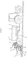
- This seed drill 1 consists of a chassis 2 trailed coupled to a motor vehicle of a tractor by means of a suitable coupling, as shown in the figure 1.
- This chassis 2 equipped with wheels preferably arranged at the rear of said chassis, supports a hopper 3. Due to this installation of the hopper 3 on the rolling chassis 2, this hopper 3 can be of large capacity (2000 to 3500 kg), a necessary condition for autonomy sufficient of the seed drill even in the case of working on large width.
- the hopper 3 is combined with a device for dosing products to be distributed, a device for conveying said products metered products transporting these in the vicinity of implantation organs also called sowing elements 5 and a device for distributing said dosed products to said sowing elements 5.
- the products to distribute consist of seeds.
- the device of seeds is generally of the type pneumatic. So, for example, a fan 4 arranged, on the supporting frame 2, at the front of the hopper 3 ensures automatic seed transport backwards of the chassis 2 to distribute them to the sowing elements 5.
- the distribution device is of the type mechanical. It should be noted that all of the devices used for the dosage of seeds, the transport of seeds, seed distribution and seed placement in the ground can be devices perfectly classic and well known to those versed in this art.
- Each sowing element 5 can affect a large number of shapes. It can also be fitted with a covering intended to equalize the surface of the ground and to cover the seeds in the soil properly.
- All of the sowing elements 5 allowing the arrangement seeds in the soil is carried by half-ramps 7, of preferably independent, articulated on a central section 6, this central section 6 being itself carried by the chassis 2 at the back of the latter.
- Central section 6 and half-ramps 7 constitute a set called element holder set sowers 5.
- the central section 6 of the assembly sowing element carrier 5 is connected to chassis 2 by means a connecting member 13 allowing positioning at adjustable height of said central section 6 relative to said chassis 2.
- This connecting member 13 is preferably consisting of a hitch equipped with a lifting system allowing the central section 6 to be raised relative to the chassis 2.
- the sowing unit assembly 5 includes, in addition to a central section 6, two half-ramps 7 articulated on the side and on the other of said central section 6. These two half-ramps 7 are preferably independently operated to provide a greater number of maneuvering possibilities.
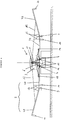
- Each half-ramp 7 consists of at least two elements of successive ramp, namely an interior element 7A and a external element 7B. These interior and exterior elements are each articulated around an axis substantially horizontal parallel to the direction of advance of the seed drill. Thus, the inner element 7A is articulated around an axis 8, while the external element 7B is articulated around an axis 9 of articulation.
- These interior elements and are additionally equipped with at least respectively a support member on the ground.
- each element inside 7A and outside 7B of each half-ramp 7 extends at least substantially horizontally and transversely to the direction of movement of the seed drill.
- Each element 7A or 7B of half-ramp 7 is further provided at least one actuating member arranged to allow in particular the free pivoting of said element around its articulation axis when said ramp element is in ground support.
- the external element 7B can freely pivot around its hinge pin 9 when it is resting on the ground, in particular by means of the wheel 10, while the element interior 7A can freely rotate around its axis of articulation 8 despite the presence of its organ 12.
- This freely pivoting mounting, preferably within an angular range predetermined, of each half-ramp element, in position work of said half-ramp, allows the entire half-ramp to perfectly follow the profile of the terrain. he this results in maximum working efficiency in terms of sowing elements 5.
- sowing elements 5 penetrate the ground and can fulfill their function. This would not have been the case if joints 8 and 9 had been joints locked in the working position and if, for example, the wheel 10 of element 7B had to pass over a bump. In this case, part of the elements sowers 5 raised above the ground could not have fulfilled its function.
- the actuators 11 and 12 of the elements 7A and 7B of each half-ramp 7 are arranged for allow controlled pivoting of each ramp element around its axis of articulation, in particular, for the passage of said ramp element from a working position to a transport position in which said element of ramp extends substantially vertically and transversely to the direction of movement of the drill, Or vice versa.
- Such displacement by controlled pivoting and controlled ramp elements 7A, 7B is notably shown in Figure 5.
- these actuators 11 respectively 12 of elements 7A respectively 7B of each half-ramp 7 are coupling members which couple each element 7A or 7B of half-ramp 7 to another half-ramp element 7 and / or with the central section 6.
- the body actuation 12 of the external element 7B of each half-ramp 7 is a cable anchored at one of its ends to the external element 7B of half-ramp 7 and to its other end on a moving part 14 carried by said section central 6.
- This part 14 ensures, during its reciprocating, tensioning or loosening the cable to allow, in the stretched state of the cable, a controlled pivoting of said half-ramp element 7B 7 and, at the loose state of the cable, free pivoting of said element 7B of half-ramp 7 around its axis 9 of articulation.
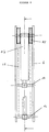
- the detail of this moving part 14 is notably shown in Figure 6.
- the central section 6 is constituted by a simple frame. Of them amounts of this frame are connected by means of a cross which constitutes the moving part 14.
- This crosspiece 14 is capable of sliding along the uprights of the frame 6 to go from a low position to a high position and Conversely.
- This displacement is obtained by means of a jack 17 whose body is fixed to a second crosspiece of said frame constituting the central section 6 and whose rod is subject to said moving part 14.
- the axis, to which is fixed the cylinder body, carries two pulleys 15 also arranged between the uprights of frame 6.
- the cable 12 wraps at least partially around these pulleys 15.
- this cable 12 passes above the articulation 9 between said elements inside 7A and outside 7B of each half-ramp 7 and is supported on at least one of said interior elements 7A or outside 7B, for example by means of a roller or of an appropriate support piece 16, for example in the form quarter circle, before coming to wind at least partially around said pulley 15 and to be fixed to the moving part 14.
- the inner end of the outer element 7B and the outer end of the element 7A carry so fixed on their upper face a sector in an arc 16 whose respective centers form with the axis of articulation 9 an isosceles triangle.
- the extension of the jack 17 ensures the lowering of the part mobile 14 and consequently the tension of the cable 12. Conversely, the retraction of the jack 17 generates a rise in the part mobile 14 and consequently a relaxation of the cable 12.
- This design of the actuator is the same as it is the actuating member 12 of the element outside 7B of the right-hand or left-hand half-ramp 7 in Figure 3.
- the actuator 11 of the inner element 7A of each half-ramp 7 is itself made up of a jack 11 one end of which is fixed to the central section 6 and the other end of which is housed in a lumen 18 of said inner element 7A of half-ramp 7 for power, in working position of the seed drill, allow, by a displacement free from the end of said cylinder inside said light 18, free pivoting of said half-ramp element 7A 7 around its axis of articulation inside a predetermined angular range.
- the central section 6 of the sower unit assembly 5 is provided with at least two stops (not shown) which respectively limit the pivoting towards the ground of said elements interior 7A half-ramp 7 to prevent any risk damage to their respective actuator 11. Thanks to these stops, in particular, an effort of too much traction, especially on the rod cylinder 11, when said cylinder is in the working position.
- each half-ramp element 7A, 7B is resting on the ground via the wheel 10.
- the joints 8 and 9 are released because the cable 12 is loose, while the cylinder 11 moves freely at inside its light 18. This results in a pivoting free of said joints and, in particular of joint 8 within a predetermined angular range corresponding to the size of the light 18.
- the articulation 9 with a horizontal axis is made in such a way that the external element 7B of half-ramp is articulated on the outer end of the element interior 7A.
- This articulation 9 is located at the part lower of the external and internal elements thanks to screeds integral respectively with the inner element 7A and of the external element 7B so as to allow the mode tilting of said elements as will be described below.
- these screeds affect the shape of a V, the hinge pin 9 being positioned at the tip of the V.
- each half-ramp element In the working position, as shown in Figure 2, each half-ramp element is arranged substantially horizontally and transversely to the axis of advancement of the seeder.
- the joints 8, 9 are free, the cable 12 is relaxed.
- cable 12 is tensioned by lowering the workpiece mobile 14, which generates a pulling force on the external elements 7B of half-ramp and, consequently, their recovery.
- the connecting member 13 between the chassis 2 and the central section 6 comes into high abutment and ensures lifting or lifting of the central section 6 on which are fixed the interior elements 7A of half-ramp 7.
- Such a position as shown in FIG. 4, also has the advantage of limiting the risks for attaching the external elements 7B of half-ramp.
- sowing elements 5 carried respectively by the exterior half-ramp elements 7B and interior 7A, are offset axially to form two rows parallels of sowing elements.
Landscapes
- Life Sciences & Earth Sciences (AREA)
- Soil Sciences (AREA)
- Environmental Sciences (AREA)
- Engineering & Computer Science (AREA)
- Mechanical Engineering (AREA)
- Insects & Arthropods (AREA)
- Pest Control & Pesticides (AREA)
- Wood Science & Technology (AREA)
- Zoology (AREA)
- Sowing (AREA)
Applications Claiming Priority (2)
| Application Number | Priority Date | Filing Date | Title |
|---|---|---|---|
| FR9615349 | 1996-12-13 | ||
| FR9615349A FR2757013B1 (fr) | 1996-12-13 | 1996-12-13 | Semoir a grande largeur de travail |
Publications (1)
| Publication Number | Publication Date |
|---|---|
| EP0847683A1 true EP0847683A1 (de) | 1998-06-17 |
Family
ID=9498650
Family Applications (1)
| Application Number | Title | Priority Date | Filing Date |
|---|---|---|---|
| EP97403031A Withdrawn EP0847683A1 (de) | 1996-12-13 | 1997-12-12 | Grossflächen-Drillmaschine |
Country Status (2)
| Country | Link |
|---|---|
| EP (1) | EP0847683A1 (de) |
| FR (1) | FR2757013B1 (de) |
Cited By (3)
| Publication number | Priority date | Publication date | Assignee | Title |
|---|---|---|---|---|
| ES2177361A1 (es) * | 1999-05-26 | 2002-12-01 | Julio Gil Agueda E Hijos S A | Perfeccionamientos en los chasis para sembradora neumatica de chorrillo. |
| EP1285563A1 (de) * | 2001-08-16 | 2003-02-26 | Amazonen-Werke H. Dreyer GmbH & Co. KG | Sämaschine |
| EP3574728A1 (de) * | 2018-05-29 | 2019-12-04 | Kverneland Group Les Landes Genusson S.A.S. | Bodenbearbeitungsmaschine und verfahren zum falten von abschnitten einer bodenbearbeitungsmaschine |
Families Citing this family (1)
| Publication number | Priority date | Publication date | Assignee | Title |
|---|---|---|---|---|
| WO2022160016A1 (en) * | 2021-01-31 | 2022-08-04 | Steamwand Technology Pty Ltd | System and apparatus for facilitating vegetation control |
Citations (4)
| Publication number | Priority date | Publication date | Assignee | Title |
|---|---|---|---|---|
| US3643742A (en) * | 1969-01-02 | 1972-02-22 | Erwin W Wellendorf | Foldup implement |
| FR2450035A1 (fr) * | 1979-02-28 | 1980-09-26 | Mahe Jean | Traceur et appareil de traitement en localise pour travaux de grandes largeurs en agriculture |
| GB2105962A (en) * | 1981-09-25 | 1983-04-07 | Oeverums Bruk Ab | Spreading boom for a distributor for fertilizer or other material |
| WO1986007522A1 (en) * | 1985-06-20 | 1986-12-31 | Ranflo Försäljnings Ab | Arrangement for a roller with a number of folding outer sections |
-
1996
- 1996-12-13 FR FR9615349A patent/FR2757013B1/fr not_active Expired - Fee Related
-
1997
- 1997-12-12 EP EP97403031A patent/EP0847683A1/de not_active Withdrawn
Patent Citations (4)
| Publication number | Priority date | Publication date | Assignee | Title |
|---|---|---|---|---|
| US3643742A (en) * | 1969-01-02 | 1972-02-22 | Erwin W Wellendorf | Foldup implement |
| FR2450035A1 (fr) * | 1979-02-28 | 1980-09-26 | Mahe Jean | Traceur et appareil de traitement en localise pour travaux de grandes largeurs en agriculture |
| GB2105962A (en) * | 1981-09-25 | 1983-04-07 | Oeverums Bruk Ab | Spreading boom for a distributor for fertilizer or other material |
| WO1986007522A1 (en) * | 1985-06-20 | 1986-12-31 | Ranflo Försäljnings Ab | Arrangement for a roller with a number of folding outer sections |
Cited By (4)
| Publication number | Priority date | Publication date | Assignee | Title |
|---|---|---|---|---|
| ES2177361A1 (es) * | 1999-05-26 | 2002-12-01 | Julio Gil Agueda E Hijos S A | Perfeccionamientos en los chasis para sembradora neumatica de chorrillo. |
| EP1285563A1 (de) * | 2001-08-16 | 2003-02-26 | Amazonen-Werke H. Dreyer GmbH & Co. KG | Sämaschine |
| EP3574728A1 (de) * | 2018-05-29 | 2019-12-04 | Kverneland Group Les Landes Genusson S.A.S. | Bodenbearbeitungsmaschine und verfahren zum falten von abschnitten einer bodenbearbeitungsmaschine |
| WO2019229189A1 (en) | 2018-05-29 | 2019-12-05 | Kverneland Group Les Landes Génusson S.A.S. | Soil tillage implement and method for folding sections of soil tillage implement |
Also Published As
| Publication number | Publication date |
|---|---|
| FR2757013B1 (fr) | 1999-02-19 |
| FR2757013A1 (fr) | 1998-06-19 |
Similar Documents
| Publication | Publication Date | Title |
|---|---|---|
| FR2636567A1 (fr) | Dispositif pour limiter le pivotement d'un attelage de tracteur agricole | |
| FR2746576A1 (fr) | Machine agricole du genre faneuse a rateaux rotatifs multiples, convertible d'une position de travail deployee a une position de transport ramassee | |
| FR2757013A1 (fr) | Semoir a grande largeur de travail | |
| EP1195084B1 (de) | Verbesserts Sämaschine | |
| EP0737416B1 (de) | Zustreichvorrichtung für eine Sämaschine | |
| EP0692179B1 (de) | Sämaschine mit einer grossen Arbeitsbreite | |
| FR2772228A1 (fr) | Ramasseur repliable pour ensileuse | |
| EP0966874B1 (de) | Sähmaschine | |
| EP0966875B1 (de) | Sähmaschine | |
| FR2640111A1 (fr) | Herse rotative | |
| FR2551308A1 (fr) | Machine pour travailler le sol munie de moyens de relevage perfectionnes | |
| FR2652230A1 (fr) | Semoir repliable perfectionne. | |
| EP0733302B1 (de) | Heuwerbungsmaschine | |
| EP0914766B1 (de) | Heuwerbungsmachine | |
| FR2643776A1 (fr) | Dispositif de guidage et de commande d'une machine agricole soumise en service a une forte poussee laterale par rapport a sa direction de traction, telle qu'une dechaumeuse a disques | |
| FR2857560A3 (fr) | Faucheuse attelable de grande surface | |
| FR2526626A1 (fr) | Combinaison d'instruments agricoles comprenant notamment un instrument de travail du sol et un semoir mecanique | |
| FR2606246A1 (fr) | Bineuse equipee d'une tremie a engrais | |
| FR2556920A1 (fr) | Machine pour repandre une matiere sur une surface | |
| FR2646315A1 (fr) | Machine agricole comportant au moins un rotor muni d'outils et s'appuyant sur le sol durant le travail | |
| FR3064879B1 (fr) | Systeme d'entrainement d'une machine agricole comportant une roue d'entrainement en contact avec le sol escamotable en position transport, et machine agricole avec un tel systeme d'entrainement | |
| EP3108730B1 (de) | Landwirtschaftliche maschine mit einer seitlich versetzbaren werkzeuggruppe | |
| FR2519835A1 (fr) | Dispositif d'attelage pour instrument agricole tracte | |
| FR3139973A1 (fr) | Machine agricole comportant une arche et un système de fixation particulier fixé à l’arche et assurant la fixation d’un outil | |
| EP0808557A1 (de) | Faltbare Boden- oder Gewachsbearbeitungsmaschine |
Legal Events
| Date | Code | Title | Description |
|---|---|---|---|
| PUAI | Public reference made under article 153(3) epc to a published international application that has entered the european phase |
Free format text: ORIGINAL CODE: 0009012 |
|
| AK | Designated contracting states |
Kind code of ref document: A1 Designated state(s): AT BE CH DE DK ES FI FR GB GR IE IT LI LU MC NL PT SE |
|
| AX | Request for extension of the european patent |
Free format text: AL;LT;LV;MK;RO;SI |
|
| AKX | Designation fees paid | ||
| RBV | Designated contracting states (corrected) | ||
| STAA | Information on the status of an ep patent application or granted ep patent |
Free format text: STATUS: THE APPLICATION IS DEEMED TO BE WITHDRAWN |
|
| 18D | Application deemed to be withdrawn |
Effective date: 19981218 |