EP0847794A1 - Verfahren und Vorrichtung zur Gasreinigung - Google Patents
Verfahren und Vorrichtung zur Gasreinigung Download PDFInfo
- Publication number
- EP0847794A1 EP0847794A1 EP97402973A EP97402973A EP0847794A1 EP 0847794 A1 EP0847794 A1 EP 0847794A1 EP 97402973 A EP97402973 A EP 97402973A EP 97402973 A EP97402973 A EP 97402973A EP 0847794 A1 EP0847794 A1 EP 0847794A1
- Authority
- EP
- European Patent Office
- Prior art keywords
- gas
- tube
- exciter
- installation according
- plasma
- Prior art date
- Legal status (The legal status is an assumption and is not a legal conclusion. Google has not performed a legal analysis and makes no representation as to the accuracy of the status listed.)
- Withdrawn
Links
- 238000009434 installation Methods 0.000 title claims abstract description 59
- 238000000034 method Methods 0.000 title claims abstract description 27
- 230000008569 process Effects 0.000 title abstract description 9
- 239000012535 impurity Substances 0.000 claims abstract description 25
- 238000000746 purification Methods 0.000 claims abstract description 24
- 238000006243 chemical reaction Methods 0.000 claims abstract description 12
- 230000005684 electric field Effects 0.000 claims abstract description 11
- 239000007789 gas Substances 0.000 claims description 117
- 229910052743 krypton Inorganic materials 0.000 claims description 31
- DNNSSWSSYDEUBZ-UHFFFAOYSA-N krypton atom Chemical compound [Kr] DNNSSWSSYDEUBZ-UHFFFAOYSA-N 0.000 claims description 31
- 150000001875 compounds Chemical class 0.000 claims description 23
- IJGRMHOSHXDMSA-UHFFFAOYSA-N Atomic nitrogen Chemical compound N#N IJGRMHOSHXDMSA-UHFFFAOYSA-N 0.000 claims description 14
- 238000001816 cooling Methods 0.000 claims description 14
- VNWKTOKETHGBQD-UHFFFAOYSA-N methane Chemical compound C VNWKTOKETHGBQD-UHFFFAOYSA-N 0.000 claims description 14
- 229910052724 xenon Inorganic materials 0.000 claims description 14
- FHNFHKCVQCLJFQ-UHFFFAOYSA-N xenon atom Chemical compound [Xe] FHNFHKCVQCLJFQ-UHFFFAOYSA-N 0.000 claims description 14
- VYPSYNLAJGMNEJ-UHFFFAOYSA-N Silicium dioxide Chemical compound O=[Si]=O VYPSYNLAJGMNEJ-UHFFFAOYSA-N 0.000 claims description 13
- HUAUNKAZQWMVFY-UHFFFAOYSA-M sodium;oxocalcium;hydroxide Chemical compound [OH-].[Na+].[Ca]=O HUAUNKAZQWMVFY-UHFFFAOYSA-M 0.000 claims description 8
- QVGXLLKOCUKJST-UHFFFAOYSA-N atomic oxygen Chemical compound [O] QVGXLLKOCUKJST-UHFFFAOYSA-N 0.000 claims description 7
- 229910052757 nitrogen Inorganic materials 0.000 claims description 7
- 239000001301 oxygen Substances 0.000 claims description 7
- 229910052760 oxygen Inorganic materials 0.000 claims description 7
- 238000012545 processing Methods 0.000 claims description 7
- 230000005284 excitation Effects 0.000 claims description 6
- 239000000377 silicon dioxide Substances 0.000 claims description 6
- 230000000750 progressive effect Effects 0.000 claims description 5
- TXEYQDLBPFQVAA-UHFFFAOYSA-N tetrafluoromethane Chemical compound FC(F)(F)F TXEYQDLBPFQVAA-UHFFFAOYSA-N 0.000 claims description 5
- 238000011144 upstream manufacturing Methods 0.000 claims description 5
- 230000018044 dehydration Effects 0.000 claims description 4
- 238000006297 dehydration reaction Methods 0.000 claims description 4
- 238000010494 dissociation reaction Methods 0.000 claims description 4
- 230000005593 dissociations Effects 0.000 claims description 4
- 239000004020 conductor Substances 0.000 claims description 3
- 239000000112 cooling gas Substances 0.000 claims description 3
- 230000008030 elimination Effects 0.000 claims description 3
- 238000003379 elimination reaction Methods 0.000 claims description 3
- 239000007864 aqueous solution Substances 0.000 claims description 2
- 239000002826 coolant Substances 0.000 claims description 2
- 210000002381 plasma Anatomy 0.000 description 54
- 210000004027 cell Anatomy 0.000 description 10
- XKRFYHLGVUSROY-UHFFFAOYSA-N Argon Chemical compound [Ar] XKRFYHLGVUSROY-UHFFFAOYSA-N 0.000 description 8
- 239000007787 solid Substances 0.000 description 8
- 238000004821 distillation Methods 0.000 description 7
- 239000000203 mixture Substances 0.000 description 7
- XLYOFNOQVPJJNP-UHFFFAOYSA-N water Substances O XLYOFNOQVPJJNP-UHFFFAOYSA-N 0.000 description 7
- 238000004458 analytical method Methods 0.000 description 6
- 229910052751 metal Inorganic materials 0.000 description 6
- 239000002184 metal Substances 0.000 description 6
- 239000000463 material Substances 0.000 description 5
- 230000005855 radiation Effects 0.000 description 5
- 229920006362 Teflon® Polymers 0.000 description 4
- 230000009471 action Effects 0.000 description 4
- 229910052786 argon Inorganic materials 0.000 description 4
- 230000007423 decrease Effects 0.000 description 4
- 239000007788 liquid Substances 0.000 description 4
- 239000002245 particle Substances 0.000 description 4
- 229920000642 polymer Polymers 0.000 description 4
- 229910001220 stainless steel Inorganic materials 0.000 description 4
- 239000010935 stainless steel Substances 0.000 description 4
- 230000009466 transformation Effects 0.000 description 4
- 238000012550 audit Methods 0.000 description 3
- 230000015556 catabolic process Effects 0.000 description 3
- 238000006731 degradation reaction Methods 0.000 description 3
- 239000000499 gel Substances 0.000 description 3
- 238000010438 heat treatment Methods 0.000 description 3
- 238000001228 spectrum Methods 0.000 description 3
- 239000000126 substance Substances 0.000 description 3
- 235000008733 Citrus aurantifolia Nutrition 0.000 description 2
- 238000004566 IR spectroscopy Methods 0.000 description 2
- 235000011941 Tilia x europaea Nutrition 0.000 description 2
- 238000000862 absorption spectrum Methods 0.000 description 2
- 230000002378 acidificating effect Effects 0.000 description 2
- 230000005540 biological transmission Effects 0.000 description 2
- 230000000903 blocking effect Effects 0.000 description 2
- 229910052799 carbon Inorganic materials 0.000 description 2
- 239000003153 chemical reaction reagent Substances 0.000 description 2
- 230000006378 damage Effects 0.000 description 2
- 238000006073 displacement reaction Methods 0.000 description 2
- 239000012634 fragment Substances 0.000 description 2
- 238000002329 infrared spectrum Methods 0.000 description 2
- 239000004571 lime Substances 0.000 description 2
- 238000012423 maintenance Methods 0.000 description 2
- 230000004048 modification Effects 0.000 description 2
- 238000012986 modification Methods 0.000 description 2
- 239000002808 molecular sieve Substances 0.000 description 2
- 230000007935 neutral effect Effects 0.000 description 2
- 229920013639 polyalphaolefin Polymers 0.000 description 2
- 238000011002 quantification Methods 0.000 description 2
- 239000000741 silica gel Substances 0.000 description 2
- 229910002027 silica gel Inorganic materials 0.000 description 2
- URGAHOPLAPQHLN-UHFFFAOYSA-N sodium aluminosilicate Chemical compound [Na+].[Al+3].[O-][Si]([O-])=O.[O-][Si]([O-])=O URGAHOPLAPQHLN-UHFFFAOYSA-N 0.000 description 2
- 229910016036 BaF 2 Inorganic materials 0.000 description 1
- OKTJSMMVPCPJKN-UHFFFAOYSA-N Carbon Chemical compound [C] OKTJSMMVPCPJKN-UHFFFAOYSA-N 0.000 description 1
- RYGMFSIKBFXOCR-UHFFFAOYSA-N Copper Chemical compound [Cu] RYGMFSIKBFXOCR-UHFFFAOYSA-N 0.000 description 1
- 238000005033 Fourier transform infrared spectroscopy Methods 0.000 description 1
- UFHFLCQGNIYNRP-UHFFFAOYSA-N Hydrogen Chemical compound [H][H] UFHFLCQGNIYNRP-UHFFFAOYSA-N 0.000 description 1
- DGAQECJNVWCQMB-PUAWFVPOSA-M Ilexoside XXIX Chemical compound C[C@@H]1CC[C@@]2(CC[C@@]3(C(=CC[C@H]4[C@]3(CC[C@@H]5[C@@]4(CC[C@@H](C5(C)C)OS(=O)(=O)[O-])C)C)[C@@H]2[C@]1(C)O)C)C(=O)O[C@H]6[C@@H]([C@H]([C@@H]([C@H](O6)CO)O)O)O.[Na+] DGAQECJNVWCQMB-PUAWFVPOSA-M 0.000 description 1
- CDBYLPFSWZWCQE-UHFFFAOYSA-L Sodium Carbonate Chemical compound [Na+].[Na+].[O-]C([O-])=O CDBYLPFSWZWCQE-UHFFFAOYSA-L 0.000 description 1
- 229910000831 Steel Inorganic materials 0.000 description 1
- QCWXUUIWCKQGHC-UHFFFAOYSA-N Zirconium Chemical compound [Zr] QCWXUUIWCKQGHC-UHFFFAOYSA-N 0.000 description 1
- 238000002835 absorbance Methods 0.000 description 1
- 238000010521 absorption reaction Methods 0.000 description 1
- 239000002253 acid Substances 0.000 description 1
- 239000002671 adjuvant Substances 0.000 description 1
- 239000012670 alkaline solution Substances 0.000 description 1
- 230000002238 attenuated effect Effects 0.000 description 1
- 230000033228 biological regulation Effects 0.000 description 1
- 230000015572 biosynthetic process Effects 0.000 description 1
- 239000006229 carbon black Substances 0.000 description 1
- 229910002091 carbon monoxide Inorganic materials 0.000 description 1
- 230000008859 change Effects 0.000 description 1
- 238000002485 combustion reaction Methods 0.000 description 1
- 238000004891 communication Methods 0.000 description 1
- 239000012141 concentrate Substances 0.000 description 1
- 238000009833 condensation Methods 0.000 description 1
- 230000005494 condensation Effects 0.000 description 1
- 239000000470 constituent Substances 0.000 description 1
- 238000010276 construction Methods 0.000 description 1
- 230000008602 contraction Effects 0.000 description 1
- 238000007796 conventional method Methods 0.000 description 1
- 239000000110 cooling liquid Substances 0.000 description 1
- 229910052802 copper Inorganic materials 0.000 description 1
- 239000010949 copper Substances 0.000 description 1
- 230000002089 crippling effect Effects 0.000 description 1
- 238000000354 decomposition reaction Methods 0.000 description 1
- 230000003247 decreasing effect Effects 0.000 description 1
- 238000001514 detection method Methods 0.000 description 1
- 238000011161 development Methods 0.000 description 1
- 239000003989 dielectric material Substances 0.000 description 1
- 238000009826 distribution Methods 0.000 description 1
- 238000001035 drying Methods 0.000 description 1
- 230000000694 effects Effects 0.000 description 1
- 238000010891 electric arc Methods 0.000 description 1
- 230000005672 electromagnetic field Effects 0.000 description 1
- 238000000295 emission spectrum Methods 0.000 description 1
- 238000000605 extraction Methods 0.000 description 1
- 230000002349 favourable effect Effects 0.000 description 1
- 238000011049 filling Methods 0.000 description 1
- 229920002313 fluoropolymer Polymers 0.000 description 1
- 230000004927 fusion Effects 0.000 description 1
- 239000001257 hydrogen Substances 0.000 description 1
- 229910052739 hydrogen Inorganic materials 0.000 description 1
- 230000002427 irreversible effect Effects 0.000 description 1
- 238000004519 manufacturing process Methods 0.000 description 1
- 238000013021 overheating Methods 0.000 description 1
- 238000009832 plasma treatment Methods 0.000 description 1
- 239000002243 precursor Substances 0.000 description 1
- 230000009467 reduction Effects 0.000 description 1
- 230000008439 repair process Effects 0.000 description 1
- 230000004044 response Effects 0.000 description 1
- 238000005070 sampling Methods 0.000 description 1
- 238000007789 sealing Methods 0.000 description 1
- 238000000926 separation method Methods 0.000 description 1
- 238000004513 sizing Methods 0.000 description 1
- 229910052708 sodium Inorganic materials 0.000 description 1
- 239000011734 sodium Substances 0.000 description 1
- 239000000243 solution Substances 0.000 description 1
- 238000001179 sorption measurement Methods 0.000 description 1
- 238000002336 sorption--desorption measurement Methods 0.000 description 1
- 230000002269 spontaneous effect Effects 0.000 description 1
- 230000006641 stabilisation Effects 0.000 description 1
- 238000011105 stabilization Methods 0.000 description 1
- 239000010959 steel Substances 0.000 description 1
- 238000012549 training Methods 0.000 description 1
- 238000000844 transformation Methods 0.000 description 1
- 230000001131 transforming effect Effects 0.000 description 1
- 230000001052 transient effect Effects 0.000 description 1
- WFKWXMTUELFFGS-UHFFFAOYSA-N tungsten Chemical compound [W] WFKWXMTUELFFGS-UHFFFAOYSA-N 0.000 description 1
- 229910052721 tungsten Inorganic materials 0.000 description 1
- 239000010937 tungsten Substances 0.000 description 1
- 229910052726 zirconium Inorganic materials 0.000 description 1
Images
Classifications
-
- B—PERFORMING OPERATIONS; TRANSPORTING
- B01—PHYSICAL OR CHEMICAL PROCESSES OR APPARATUS IN GENERAL
- B01D—SEPARATION
- B01D53/00—Separation of gases or vapours; Recovering vapours of volatile solvents from gases; Chemical or biological purification of waste gases, e.g. engine exhaust gases, smoke, fumes, flue gases, aerosols
- B01D53/32—Separation of gases or vapours; Recovering vapours of volatile solvents from gases; Chemical or biological purification of waste gases, e.g. engine exhaust gases, smoke, fumes, flue gases, aerosols by electrical effects other than those provided for in group B01D61/00
- B01D53/323—Separation of gases or vapours; Recovering vapours of volatile solvents from gases; Chemical or biological purification of waste gases, e.g. engine exhaust gases, smoke, fumes, flue gases, aerosols by electrical effects other than those provided for in group B01D61/00 by electrostatic effects or by high-voltage electric fields
-
- C—CHEMISTRY; METALLURGY
- C01—INORGANIC CHEMISTRY
- C01B—NON-METALLIC ELEMENTS; COMPOUNDS THEREOF; METALLOIDS OR COMPOUNDS THEREOF NOT COVERED BY SUBCLASS C01C
- C01B23/00—Noble gases; Compounds thereof
- C01B23/001—Purification or separation processes of noble gases
- C01B23/0094—Combined chemical and physical processing
-
- F—MECHANICAL ENGINEERING; LIGHTING; HEATING; WEAPONS; BLASTING
- F25—REFRIGERATION OR COOLING; COMBINED HEATING AND REFRIGERATION SYSTEMS; HEAT PUMP SYSTEMS; MANUFACTURE OR STORAGE OF ICE; LIQUEFACTION SOLIDIFICATION OF GASES
- F25J—LIQUEFACTION, SOLIDIFICATION OR SEPARATION OF GASES OR GASEOUS OR LIQUEFIED GASEOUS MIXTURES BY PRESSURE AND COLD TREATMENT OR BY BRINGING THEM INTO THE SUPERCRITICAL STATE
- F25J3/00—Processes or apparatus for separating the constituents of gaseous or liquefied gaseous mixtures involving the use of liquefaction or solidification
- F25J3/02—Processes or apparatus for separating the constituents of gaseous or liquefied gaseous mixtures involving the use of liquefaction or solidification by rectification, i.e. by continuous interchange of heat and material between a vapour stream and a liquid stream
- F25J3/04—Processes or apparatus for separating the constituents of gaseous or liquefied gaseous mixtures involving the use of liquefaction or solidification by rectification, i.e. by continuous interchange of heat and material between a vapour stream and a liquid stream for air
- F25J3/04642—Recovering noble gases from air
- F25J3/04745—Krypton and/or Xenon
- F25J3/04751—Producing pure krypton and/or xenon recovered from a crude krypton/xenon mixture
- F25J3/04757—Producing pure krypton and/or xenon recovered from a crude krypton/xenon mixture using a hybrid system, e.g. using adsorption, permeation or catalytic reaction
-
- B—PERFORMING OPERATIONS; TRANSPORTING
- B01—PHYSICAL OR CHEMICAL PROCESSES OR APPARATUS IN GENERAL
- B01D—SEPARATION
- B01D2257/00—Components to be removed
- B01D2257/20—Halogens or halogen compounds
- B01D2257/206—Organic halogen compounds
-
- B—PERFORMING OPERATIONS; TRANSPORTING
- B01—PHYSICAL OR CHEMICAL PROCESSES OR APPARATUS IN GENERAL
- B01D—SEPARATION
- B01D2257/00—Components to be removed
- B01D2257/70—Organic compounds not provided for in groups B01D2257/00 - B01D2257/602
- B01D2257/702—Hydrocarbons
-
- C—CHEMISTRY; METALLURGY
- C01—INORGANIC CHEMISTRY
- C01B—NON-METALLIC ELEMENTS; COMPOUNDS THEREOF; METALLOIDS OR COMPOUNDS THEREOF NOT COVERED BY SUBCLASS C01C
- C01B2210/00—Purification or separation of specific gases
- C01B2210/0001—Separation or purification processing
- C01B2210/0003—Chemical processing
-
- C—CHEMISTRY; METALLURGY
- C01—INORGANIC CHEMISTRY
- C01B—NON-METALLIC ELEMENTS; COMPOUNDS THEREOF; METALLOIDS OR COMPOUNDS THEREOF NOT COVERED BY SUBCLASS C01C
- C01B2210/00—Purification or separation of specific gases
- C01B2210/0001—Separation or purification processing
- C01B2210/0009—Physical processing
-
- C—CHEMISTRY; METALLURGY
- C01—INORGANIC CHEMISTRY
- C01B—NON-METALLIC ELEMENTS; COMPOUNDS THEREOF; METALLOIDS OR COMPOUNDS THEREOF NOT COVERED BY SUBCLASS C01C
- C01B2210/00—Purification or separation of specific gases
- C01B2210/0029—Obtaining noble gases
- C01B2210/0035—Krypton
-
- C—CHEMISTRY; METALLURGY
- C01—INORGANIC CHEMISTRY
- C01B—NON-METALLIC ELEMENTS; COMPOUNDS THEREOF; METALLOIDS OR COMPOUNDS THEREOF NOT COVERED BY SUBCLASS C01C
- C01B2210/00—Purification or separation of specific gases
- C01B2210/0029—Obtaining noble gases
- C01B2210/0037—Xenon
-
- C—CHEMISTRY; METALLURGY
- C01—INORGANIC CHEMISTRY
- C01B—NON-METALLIC ELEMENTS; COMPOUNDS THEREOF; METALLOIDS OR COMPOUNDS THEREOF NOT COVERED BY SUBCLASS C01C
- C01B2210/00—Purification or separation of specific gases
- C01B2210/0043—Impurity removed
- C01B2210/0068—Organic compounds
-
- C—CHEMISTRY; METALLURGY
- C01—INORGANIC CHEMISTRY
- C01B—NON-METALLIC ELEMENTS; COMPOUNDS THEREOF; METALLOIDS OR COMPOUNDS THEREOF NOT COVERED BY SUBCLASS C01C
- C01B2210/00—Purification or separation of specific gases
- C01B2210/0043—Impurity removed
- C01B2210/0068—Organic compounds
- C01B2210/007—Hydrocarbons
-
- F—MECHANICAL ENGINEERING; LIGHTING; HEATING; WEAPONS; BLASTING
- F25—REFRIGERATION OR COOLING; COMBINED HEATING AND REFRIGERATION SYSTEMS; HEAT PUMP SYSTEMS; MANUFACTURE OR STORAGE OF ICE; LIQUEFACTION SOLIDIFICATION OF GASES
- F25J—LIQUEFACTION, SOLIDIFICATION OR SEPARATION OF GASES OR GASEOUS OR LIQUEFIED GASEOUS MIXTURES BY PRESSURE AND COLD TREATMENT OR BY BRINGING THEM INTO THE SUPERCRITICAL STATE
- F25J2205/00—Processes or apparatus using other separation and/or other processing means
- F25J2205/86—Processes or apparatus using other separation and/or other processing means using electrical phenomena, e.g. Corona discharge, electrolysis or magnetic field
-
- Y—GENERAL TAGGING OF NEW TECHNOLOGICAL DEVELOPMENTS; GENERAL TAGGING OF CROSS-SECTIONAL TECHNOLOGIES SPANNING OVER SEVERAL SECTIONS OF THE IPC; TECHNICAL SUBJECTS COVERED BY FORMER USPC CROSS-REFERENCE ART COLLECTIONS [XRACs] AND DIGESTS
- Y02—TECHNOLOGIES OR APPLICATIONS FOR MITIGATION OR ADAPTATION AGAINST CLIMATE CHANGE
- Y02C—CAPTURE, STORAGE, SEQUESTRATION OR DISPOSAL OF GREENHOUSE GASES [GHG]
- Y02C20/00—Capture or disposal of greenhouse gases
- Y02C20/20—Capture or disposal of greenhouse gases of methane
-
- Y—GENERAL TAGGING OF NEW TECHNOLOGICAL DEVELOPMENTS; GENERAL TAGGING OF CROSS-SECTIONAL TECHNOLOGIES SPANNING OVER SEVERAL SECTIONS OF THE IPC; TECHNICAL SUBJECTS COVERED BY FORMER USPC CROSS-REFERENCE ART COLLECTIONS [XRACs] AND DIGESTS
- Y02—TECHNOLOGIES OR APPLICATIONS FOR MITIGATION OR ADAPTATION AGAINST CLIMATE CHANGE
- Y02P—CLIMATE CHANGE MITIGATION TECHNOLOGIES IN THE PRODUCTION OR PROCESSING OF GOODS
- Y02P20/00—Technologies relating to chemical industry
- Y02P20/151—Reduction of greenhouse gas [GHG] emissions, e.g. CO2
Definitions
- the present invention relates to a method purifying a gas, in particular a rare plasma gas, intended for example for the purification of krypton and xenon in tetrafluoromethane and methane, as well as an installation purification using such a process.
- a gas in particular a rare plasma gas
- Rare gases are generally extracted from the air by distillation. They contain, after distillation, impurities that need to be removed before their use.
- the impurities consist mainly of tetrafluoromethane (CF 4 ) and methane (CH 4 ) at levels which can reach a few hundred parts per million by volume (ppmv).
- CF 4 tetrafluoromethane
- CH 4 methane
- krypton is widely used for partial vacuum filling of incandescent lamps.
- the very high temperature at which is worn the tungsten filament of these lamps is sufficient to dissociate tetrafluoromethane into highly corrosive fluorinated radicals, causing the rapid degradation of the filament by chemical attack on the metal.
- methane is also dissociated, in these temperature conditions, and generates gaseous precursors unstable which form solid carbon deposits brownish in appearance on the inner surface of the bulb.
- the purification techniques known to date are based mainly on thermal phenomena.
- Another known purification technique is based on thermochemical decomposition by reaction on a metal suitable, for example zirconium. This technique is relatively effective and requires very little input important combustible gas. However, it presents many disadvantages, notably due to the fact that it it is not possible to purify gases with a high flow rate and that its implementation requires an installation having a significant bulk.
- this technique requires a temperature of fairly high operation, for example of the order of 900 to 1000 ° C, and the metal beds used are very expensive and with a limited lifespan.
- the object of the invention is to provide a method gas purification plant and a purification plant for the implementation of such a method making it possible to overcome the disadvantages mentioned above.
- the invention also relates to an installation gas purification, for the implementation of a process purification, characterized in that it comprises at least one high frequency traveling wave exciter associated with a waveguide adapted to convey traveling waves produced by said at least one wave exciter at minus a hollow dielectric tube in which said gas is intended to circulate, to create a pressure plasma atmospheric ionization and excitation of said molecules gas to be purified with a view to dissociating the impurities of said gas to form reactive compounds, in particular fluorinated compounds, and minus one processing unit for said reactive compounds disposed at the outlet of a corresponding dielectric hollow tube.
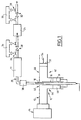
- FIG 1 there is shown a schematic view a plasma gas purification installation, in particular rare gases such as krypton or xenon.
- the invention also applies to the treatment of other gases, such as A r , N 2 , N e , K r , X e , H e , O 2 , CO 2 , H 2 or to a mixture of these gases.
- gases such as A r , N 2 , N e , K r , X e , H e , O 2 , CO 2 , H 2 or to a mixture of these gases.
- the purpose of this installation is to place the gas plasmagen to be treated in an electric field sufficient intense to achieve an electric discharge by ionization molecules of the gas, caused by the tearing of electrons initially neutral gas molecules.
- plasma gas is meant a gas in which the discharge is created under the action of the electric field and of which the properties of the discharge, namely the function of electronic distribution and physico-chemical parameters, are determined by the gas in which the landfill is created.
- the molecules of the gas are dissociated to form plus size radicals smaller than the initial molecules, and therefore atoms individual.
- the atoms or molecules, as the case may be, of the gas to purify are excited and the molecules are dissociated in the discharge into atoms or fragments of molecules.
- the species excited and / or dissociated do not, however, give rise to practically no chemical reaction, either due to their intrinsic nature (rare gas) either because we do not introduce not in landfill in significant quantity of other gas likely to react with the gas to be treated.
- the atoms or molecules of the gas to be purified are de-excite and / or recombine and are thus found intact at the outlet of the landfill.
- the impurities which are, as described previously, molecules harmful to a process subsequent using the gas to be purified and present in low quantity, undergo by excitation a dissociation and a irreversible transformation by training new ones molecular fragments with chemical properties different from the original molecules and that is either likely to be treated by reaction on a solid or a suitable liquids, either immediately condense and spontaneously in deposits or solid particles.
- the purification installation is intended to be mounted at the outlet of an air distillation installation, for the extraction of krypton and xenon with a view to the destruction of the molecules impurities, such as CF 4 and CH 4 by converting these impurities into reactive gas compounds capable of being treated by the action of corresponding reactive compounds. It can also be installed downstream from a krypton and xenon separation installation by distillation. Finally, it can constitute an independent purification installation, supplied from bottles where krypton, xenon, or a mixture of these two gases are stored under pressure.
- the installation according to the invention includes a field applicator device to high frequency, designated by reference numeral 10, consisting of a surface wave exciter, connected by through a waveguide 12, to a generator microwave 14.
- the installation also includes, associated with the surface wave exciter 10, a discharge tube 16 in dielectric material, such as silica, in which circulates a plasmogenic gas to be purified.
- dielectric material such as silica
- the surface wave exciter 10 also designated high frequency field applicator, consists of a surfatron-guide type applicator ensuring, in cooperation with waveguide 12, the routing of microwave radiation created by the microwave generator 14 to the tube at discharge 16 to create a plasma 18 in the gas to be purified.
- FIG. 1 It can also be seen in FIG. 1 that the tube to discharge 16 is placed in a sleeve 19 of material conductor whose structure will be described in detail by the continued with reference to Figure 2.
- a gas transport pipe 20 excited to a processing unit 22, consisting of a cartridge containing an alkaline element such as lime soda or an alkaline aqueous solution, and a unit of gas dehydration 24.
- a processing unit 22 consisting of a cartridge containing an alkaline element such as lime soda or an alkaline aqueous solution, and a unit of gas dehydration 24.
- the line 20 has two branch sets 26 and 28 controlled by valves corresponding, such as 30 and 32, and on which come to tightly assemble sample cells 34 and 36 for the analysis of gases by Fourier transform infrared spectrometry.
- These cells are single-pass “Spectra-Tec” type cells with a length of approximately 100 mm, which gives a detection limit that is more than sufficient for the intended application. They are made of stainless steel to avoid the generation of additional products which would not fail to appear in the case of a silica cell capable of being attacked by some of the fluorinated products following the passage of the gas in the discharge created in tube 16.
- the cell windows are made of BaF 2 , a material with very little absorption in the wavelength range considered for analysis by infrared spectrometry.
- FIG. 1 it can be seen in FIG. 1 that the discharge tube 16 is connected to line 20 via a cooling cartridge 38 whose structure will be described thereafter in detail with reference to FIG. 3.
- the applicator 10 is preferably consisting of a surfatron-guide applicator.
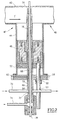
- first part 40 forming a guide wave proper intended for the transmission of radiation microwave guided by waveguide 12 and incident according to the direction indicated by arrow F in this figure and a second so-called coaxial impedance matching part 42 itself composed of a first substantially cylindrical part 44, coaxial with the discharge tube 16, in which is mounted axially displaceable a tuning piston 46 forming a trap in quarter wave and a second part 48 also substantially cylindrical arranged in the extension of the waveguide 12 and equipped with a movable piston 50 as a waveguide, shown in figure 1.
- tuning piston 46 is fixed on a sliding washer 52 advantageously made of Teflon®.
- the guide surfatron 10 is further provided with means for control of the adjustment of the axial position of the pistons 46 and 50, constituted by rods 53 and 54 which can be actuated manually by an operator or fitted with drive means, view of the impedance adjustment of the generator system microwave / waveguide with surfatron-guide / plasma system by adjusting the position of the tuning piston 46 and the waveguide piston 50.
- coaxial piston 46 ensures a contactless short circuit by quarter-wave trap allowing high power operation as well as substantially zero maintenance.
- a screw 56 is provided in the body of the guide-surfatron 10 for blocking the tuning piston 46 in position after adjustment.
- the guide surfatron is internally provided with a cylindrical sleeve 19 inside from which the discharge tube 16 is placed. It is mounted axially movable relative to the first part 44 coaxial with the discharge tube 16 and the tuning piston 46, in view of the width of the launch gap surfatron-guide.
- the body of the guide surfatron 10 includes a member for holding the sleeve 19 in position, consisting of a transverse screw 62.
- the sleeve 19 has two coaxial walls 64 and 66 delimiting between them a cylindrical chamber 68 in communication with a water cooling circuit 70, partially shown in Figure 2, and allowing to ensure the cooling of the sleeve 19 during the discharge into tube 16.
- the discharge tube 16 delimits with the inner wall 64 of the sleeve 60 a gap 72 substantially cylindrical connected to a pipe 74 supplying pressurized gas (partially shown) for cause a forced gas flow in the gap 72 between the discharge tube 16 and the sleeve 19 to ensure a additional cooling.
- the cooling gas is for example pressurized air, formed by a compressor.
- the launch gap 76 is adjustable by axial displacement of the sleeve 19 in the first coaxial part 44 and blocking with the screw 62. This setting optimizes the impedance agreement by avoiding the formation of an electric arc in the interstice of launch 76 when the installation is running at high microwave power.
- the free end 78 of the discharge tube 16 is connected to a source of gas to be treated, not shown, constituted for example by a distillation installation air, so as to circulate this gas in the guide surfatron.
- the microwave radiation produced by the generator 14 is guided by the waveguide 12 towards the guide-surfatron 10 which concentrates the incident radiation in launch gap 76 so as to spread in the discharge tube 16 and in the gas mixture which it contains a progressive electromagnetic surface wave whose associated electric field generates and maintains a discharge into the gas mixture.
- the construction of the guide-surfatron 10 allows the electric field of the incident wave to be communicated to the plasma gas in the axial direction of the tube discharge 16 through launch gap 76.
- the plasma thus generated in the gas to be purified is present as a column and its density electronics decreases from the launch gap according to a known function.
- the installation is completed by means of adjusting the longitudinal dimension of the plasma in the discharge tube 16.
- These means consist of a device for adjusting the microwave power conventionally fitted to the generator microwave 14 and allowing to adjust the dimension longitudinal of the area in which the field is created electric, the length of this area increasing, so known, when the power is increased.
- the diameter of the tube to discharge 16 is chosen sufficiently small, for example with a external diameter equal to 8 mm and an internal diameter equal to 4 mm, to obtain a single plasma filament centered on the axis of the tube which can be established in a stable and reproducible manner.
- the arrangement which has just been described makes it possible to create, on the path of a plasma gas to be purified and in it, a plasma which is the seat of very high electronic energetic excitations, corresponding to temperatures several tens of thousands of Kelvin, thus allowing, by electronic collision, to excite the atoms and molecules constituting the gas, and in particular to transform the molecules of impurities, such as CF 4 and CH 4 , of a relatively state chemically stable towards a reactive state which then makes it possible to eliminate them either following their immediate and spontaneous condensation in the form of deposits or solid particles (fluorocarbon polymers, carbon black ...) or by causing them to react with a reagent corresponding solid or liquid, as will be described later.
- thermodynamics In a system that is not in balance thermodynamics, a lot of different states can be achieved by playing on the parameters of the discharge, by example the frequency of the electromagnetic field, the diameter of the discharge tube, the absorbed microwave power density, and the composition of the gas to be treated, by adding adjuvants.
- a unit of cooling 38 is interposed between the discharge tube 16 and line 20 for the evacuation of calories in the connection area.
- krypton we contrasts a very intense heat release not at dielectric tube level, but immediately after its connection with line 20, in a region which located several tens of cm downstream of the dump. This phenomenon can be applied by de-excitation deferred from metastable energy states of krypton, due to high gas velocity in the discharge tube (strong flow and small diameter).
- the de-excitation preferably takes place in a metal pipe or in polymer with respect to the silica tube.
- line 20 quickly reaches temperatures incompatible with the maintaining its integrity, even if it is made of stainless steel (metal brought to red after a few minutes of operation).
- the installation includes therefore, at the outlet of the discharge tube, a heat exchanger made of a copper or stainless steel coil, in which the gas flow to be treated circulates, said coil being enclosed in a steel enclosure inside of which is established a circulation of water.
- the heat exchanger is dimensioned so that that the temperature of the pipeline at the outlet of this last remains sufficiently moderate under permanent operation, typically less than 100 ° C.
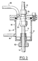
- the cartridge cooling includes a housing 80 delimiting subsequently a chamber 81 and provided at one of its ends a fitting 82 for fixing to the discharge tube 16 and to its opposite end of a flange 84 for connecting the tube to discharge 16 and line 20.
- the cartridge 38 is provided with a pipe 86 for water intake in room 81 and a pipe 88 water drain.
- the cell is isolated and the gas flows through the branch branches corresponding.
- the opening and closing sequences of valves for sampling are reproduced identically and we check that we always operate at a pressure constant in the cell.
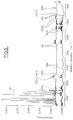
- a reference spectrum is recorded with a cell purged under pure nitrogen.
- the net transmission T of the gas sample is obtained by division with this spectrum of reference which integrates the contribution of the optics of spectrometer, the emission spectrum of the source and the detector response, both likely to drift into the weather.
- Product identification is carried out by comparison with stored reference spectra and each corresponding to a known product.
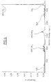
- characteristic peaks of H 2 O are observed in the vicinity of 1500 cm -1 and at wave numbers greater than 3500 cm -1 , as well as characteristic peaks of residual atmospheric CO 2 in the spectrometer compartment, at 2380 cm -1 .
- the gas to be purified does not contain no other impurities at a notable concentration.
- the gaseous effluent to be treated consists of krypton, at a flow rate of 20 1 standard / min (slm), or 1.2 m 3 / h and an incident microwave power of 1500 W.
- oxygen is added to the krypton before it circulates in the dielectric tube 16.
- the admissible oxygen concentrations in such a surface wave plasma generated in krypton are very limited compared to plasmas generated in other gases. More particularly, beyond an oxygen concentration substantially of the same order of magnitude as that of CF 4 existing in the incident gas, the plasma changes color very quickly and becomes unstable and multifilamentary.
- the maximum oxygen flow rate is preferably, for the conditions considered, fixed at 20 cm 3 standard / min (sccm).
- the adjustment of the impedance tuning of the surfatron-guide 10 is carried out by acting on the length of the launch gap 76, on the piston position coaxial agreement 46 and on the position of the guide piston wave 50.
- launch space 76 cannot be adjusted only by successive approximation, the modifications being made without switching on the plasma so as not to expose the operator to incompatible leakage radiation with safety standards.
- the residual concentration of CO in the purified gas is of the order of the value average legal exposure, i.e. 50 ppmv. It is however possible to easily extract gas purified by subsequent cryogenic distillation steps for its release to the atmosphere.
- both C 2 H 2 and CO 2 can be very easily removed by adsorption on a molecular sieve.
- the gas dehydration unit consists of a gel silica. It is however possible to replace this gel with a molecular sieve, for example of the "13X" type.
- a particulate filter can be placed downstream of the so as to avoid particles of carbonaceous solids found at the exit of the installation.
- the installation can be advantageously supplemented by a conventional humidifier placed in upstream of soda lime to avoid loss of efficiency following its gradual drying under the effect circulation of the gas to be purified in continuous operation, and bringing the circulating gas into contact with water so that this gas becomes charged with vapor.
- the description which has just been made applies to the purification of krypton and xenon, but of course the purification process described above also applies to any type of plasma gas, in particular argon, and in general for the purification of gases, such as A r , N x , N e , k r -, X e , H e , O 2 , CO 2 , H 2 .
- the invention makes it possible to purify, so particularly effective, krypton, which is capable of generate a plasma with a relatively long residence time high and whose atoms are relatively cold.
- the impurities mentioned above mainly consist of CF 4 and CH 4 , but of course the invention also applies to the purification of gases into other impurities, in particular other perfluorinated or hydrofluorocarbon gases.
- the plasma is created using a guide surfatron. It is also possible, as a variant, to endow the installation of other plasma creation devices at high frequency, for example a surfaguide or a "ro-box" in with regard to surface waves, or possibly a resonant cavity device of known type, or one of the field propagation conductive structures also known: ladder, spiral or helix structure surrounding externally the dielectric tube.
- other plasma creation devices at high frequency, for example a surfaguide or a "ro-box" in with regard to surface waves, or possibly a resonant cavity device of known type, or one of the field propagation conductive structures also known: ladder, spiral or helix structure surrounding externally the dielectric tube.
- the setting of the longitudinal dimension of the plasma is made in appropriately sizing the device for creating plasma so that it spans a sufficient length the along the discharge tube to obtain the plasma length desired.
- the invention also applies to the treatment of other gases plasmagenses, and in particular the treatment of nitrogen, gas in which plasmas reach temperatures significantly higher than in other gases, such as argon.
- the circulating coolant in the chamber 68 delimited by the dielectric tube and the outer cylinder 66 of sleeve 19 preferably consists by an isoparaffinic polyalphaolefin (PAO) sold by the company LUBRI DELTA Inc., Quebec conventionally used in hydraulic circuits.
- PAO isoparaffinic polyalphaolefin
- a wave discharge of surface in nitrogen shows less contractions radial than an argon, krypton or xenon plasma and the luminescent zone is radially delocalized throughout the section of the discharge tube.
- the internal diameter of the tube to discharge is chosen equal for example 4 mm in the case of krypton or xenon
- the internal diameter of tube 16 is increased up to a value equal to 14 mm so that increase the total flow of gas to be purified for a time of residence in the given landfill, without significantly decreasing the conversion efficiency of the impurities to be treated, and while minimizing plasma density in the vicinity of the wall internal of the tube.
- the opening in the bet of the exciter for the passage of the discharge tube 16, at the neighborhood of the incident wave concentration area 76, is chosen equal to about 13 mm in the case of use a discharge tube 16 having an internal diameter of 10 mm and a thickness of 0.5 or 1 mm.
- the other orifice provided opposite of the first in the wall of the exciter 10 for the passage of the sleeve 19 and tube 16 has a diameter substantially equal to 22mm, for a sleeve 19 having an external diameter included between 16 and 18 mm.
- the section of the wall of the guide-surfatron 10 near launch gap 76 is thinned by removal of material in the external wall of the waveguide 40 so as not to impede the excitation of surface waves.
Landscapes
- Chemical & Material Sciences (AREA)
- Chemical Kinetics & Catalysis (AREA)
- Engineering & Computer Science (AREA)
- Organic Chemistry (AREA)
- Analytical Chemistry (AREA)
- General Chemical & Material Sciences (AREA)
- General Engineering & Computer Science (AREA)
- Thermal Sciences (AREA)
- Mechanical Engineering (AREA)
- Inorganic Chemistry (AREA)
- Physics & Mathematics (AREA)
- Oil, Petroleum & Natural Gas (AREA)
- Physical Or Chemical Processes And Apparatus (AREA)
Applications Claiming Priority (2)
| Application Number | Priority Date | Filing Date | Title |
|---|---|---|---|
| FR9615370 | 1996-12-13 | ||
| FR9615370A FR2757082B1 (fr) | 1996-12-13 | 1996-12-13 | Procede d'epuration d'un gaz plasmagene et installation pour la mise en oeuvre d'un tel procede |
Publications (1)
| Publication Number | Publication Date |
|---|---|
| EP0847794A1 true EP0847794A1 (de) | 1998-06-17 |
Family
ID=9498666
Family Applications (1)
| Application Number | Title | Priority Date | Filing Date |
|---|---|---|---|
| EP97402973A Withdrawn EP0847794A1 (de) | 1996-12-13 | 1997-12-09 | Verfahren und Vorrichtung zur Gasreinigung |
Country Status (7)
| Country | Link |
|---|---|
| US (2) | US5993612A (de) |
| EP (1) | EP0847794A1 (de) |
| JP (1) | JPH10277354A (de) |
| KR (1) | KR19980064336A (de) |
| FR (1) | FR2757082B1 (de) |
| SG (1) | SG67456A1 (de) |
| TW (1) | TW436321B (de) |
Cited By (2)
| Publication number | Priority date | Publication date | Assignee | Title |
|---|---|---|---|---|
| WO2000062904A1 (en) * | 1999-04-16 | 2000-10-26 | Swinburne Limited | Ioniser for effluent gas |
| WO2002076583A3 (de) * | 2001-03-27 | 2002-11-21 | Ct Therm Elek Sche Anlagen Gmb | Anordnung und verfahren zur reinigung von abgasen |
Families Citing this family (29)
| Publication number | Priority date | Publication date | Assignee | Title |
|---|---|---|---|---|
| IL129564A (en) * | 1999-04-23 | 2004-06-20 | Atlantium Lasers Ltd | Method for disinfecting and purifying liquids and gases and a device to use therein |
| JP2001252527A (ja) * | 2000-03-13 | 2001-09-18 | Seiko Epson Corp | Pfcの処理方法および処理装置 |
| WO2001093315A2 (en) | 2000-05-25 | 2001-12-06 | Jewett Russell F | Methods and apparatus for plasma processing |
| US6623705B2 (en) * | 2000-06-20 | 2003-09-23 | Advanced Electron Beams, Inc. | Gas conversion system |
| US6623706B2 (en) * | 2000-06-20 | 2003-09-23 | Advanced Electron Beams, Inc. | Air sterilizing system |
| US7189978B2 (en) * | 2000-06-20 | 2007-03-13 | Advanced Electron Beams, Inc. | Air sterilizing system |
| FR2815888B1 (fr) * | 2000-10-27 | 2003-05-30 | Air Liquide | Dispositif de traitement de gaz par plasma |
| RU2183474C1 (ru) * | 2001-02-09 | 2002-06-20 | Пекшев Александр Валерьевич | Способ и устройство для формирования no-содержащего газового потока для воздействия на биологический объект |
| FR2825295B1 (fr) * | 2001-05-31 | 2004-05-28 | Air Liquide | Application des plasmas denses crees a pression atmospherique au traitement d'effluents gazeux |
| US6843973B2 (en) * | 2002-05-01 | 2005-01-18 | Air Products And Chemicals | Krypton and xenon recovery system |
| JP2005524963A (ja) * | 2002-05-08 | 2005-08-18 | ダナ・コーポレーション | プラズマ触媒 |
| US7497922B2 (en) | 2002-05-08 | 2009-03-03 | Btu International, Inc. | Plasma-assisted gas production |
| US7465362B2 (en) | 2002-05-08 | 2008-12-16 | Btu International, Inc. | Plasma-assisted nitrogen surface-treatment |
| US7432470B2 (en) | 2002-05-08 | 2008-10-07 | Btu International, Inc. | Surface cleaning and sterilization |
| US7638727B2 (en) | 2002-05-08 | 2009-12-29 | Btu International Inc. | Plasma-assisted heat treatment |
| US7445817B2 (en) | 2002-05-08 | 2008-11-04 | Btu International Inc. | Plasma-assisted formation of carbon structures |
| US7494904B2 (en) | 2002-05-08 | 2009-02-24 | Btu International, Inc. | Plasma-assisted doping |
| US7560657B2 (en) | 2002-05-08 | 2009-07-14 | Btu International Inc. | Plasma-assisted processing in a manufacturing line |
| US7498066B2 (en) | 2002-05-08 | 2009-03-03 | Btu International Inc. | Plasma-assisted enhanced coating |
| US7189940B2 (en) | 2002-12-04 | 2007-03-13 | Btu International Inc. | Plasma-assisted melting |
| KR100836094B1 (ko) * | 2004-01-29 | 2008-06-09 | 다다히로 오미 | 배기가스 처리방법 및 배기가스 처리장치 |
| EP1768776A2 (de) * | 2004-07-13 | 2007-04-04 | L'Air Liquide, Société Anonyme à Directoire et Conseil de Surveillance pour l'Etude et L'Exploitation des Procédés Georges Claude | Atmosphärendruckplasmabehandlung von gasförmigen austragsströmen |
| GB2442990A (en) * | 2004-10-04 | 2008-04-23 | C Tech Innovation Ltd | Microwave plasma apparatus |
| CN100352793C (zh) * | 2006-01-20 | 2007-12-05 | 杨鸿生 | 用于以天然气制乙烯的槽波导微波化学反应设备及制备方法 |
| US8906195B2 (en) * | 2009-11-18 | 2014-12-09 | Lam Research Corporation | Tuning hardware for plasma ashing apparatus and methods of use thereof |
| AU2015284596A1 (en) | 2014-06-30 | 2017-01-12 | Origin Inc. | Apparatus for applying nitric oxide to a treatment site |
| US11213786B2 (en) * | 2015-03-06 | 2022-01-04 | Mécanique Analytique Inc. | Methods and systems for managing gas purification |
| US11273282B2 (en) * | 2016-10-20 | 2022-03-15 | Vapotherm, Inc. | Vapor transfer cartridge |
| EP3554995B1 (de) | 2016-12-14 | 2023-07-12 | Origin, Inc. | Vorrichtung und verfahren zur herstellung von hochkonzentriertem niedertemperaturstickoxid |
Citations (5)
| Publication number | Priority date | Publication date | Assignee | Title |
|---|---|---|---|---|
| US5137701A (en) * | 1984-09-17 | 1992-08-11 | Mundt Randall S | Apparatus and method for eliminating unwanted materials from a gas flow line |
| DE4319118A1 (de) * | 1993-06-09 | 1994-12-15 | Breitbarth Friedrich Wilhelm D | Verfahren und Vorrichtung zur Entsorgung von Fluorkohlenstoffen und anderen fluorhaltigen Verbindungen |
| US5453125A (en) * | 1994-02-17 | 1995-09-26 | Krogh; Ole D. | ECR plasma source for gas abatement |
| EP0781599A2 (de) * | 1995-12-27 | 1997-07-02 | Applied Materials, Inc. | Verfahren und Vorrichrung zur Reduzierung von Gasen bestehend aus Perfluoroverbindungen in Abgasen von einer Substrat-Bearbeitungsvorrichtung |
| EP0820801A1 (de) * | 1996-07-26 | 1998-01-28 | L'air Liquide, Societe Anonyme Pour L'etude Et L'exploitation Des Procedes Georges Claude | Verfahren und Anlage zur Behandlung von perfluorierten und hydrofluorkohlenwasserstoffhaltigen Gasen zu ihrer Vernichtung |
Family Cites Families (3)
| Publication number | Priority date | Publication date | Assignee | Title |
|---|---|---|---|---|
| US3909206A (en) * | 1974-04-10 | 1975-09-30 | United Technologies Corp | High performance carbon dioxide scrubber |
| FR2678956B1 (fr) * | 1991-07-12 | 1993-09-24 | Pechiney Recherche | Dispositif et procede de depot de diamant par dcpv assiste par plasma microonde. |
| US5750823A (en) * | 1995-07-10 | 1998-05-12 | R.F. Environmental Systems, Inc. | Process and device for destruction of halohydrocarbons |
-
1996
- 1996-12-13 FR FR9615370A patent/FR2757082B1/fr not_active Expired - Fee Related
-
1997
- 1997-12-04 US US08/985,258 patent/US5993612A/en not_active Expired - Fee Related
- 1997-12-09 EP EP97402973A patent/EP0847794A1/de not_active Withdrawn
- 1997-12-12 SG SG1997004423A patent/SG67456A1/en unknown
- 1997-12-12 JP JP9343475A patent/JPH10277354A/ja active Pending
- 1997-12-13 TW TW086118839A patent/TW436321B/zh not_active IP Right Cessation
- 1997-12-13 KR KR1019970070465A patent/KR19980064336A/ko not_active Withdrawn
-
1999
- 1999-08-11 US US09/372,251 patent/US6190510B1/en not_active Expired - Fee Related
Patent Citations (5)
| Publication number | Priority date | Publication date | Assignee | Title |
|---|---|---|---|---|
| US5137701A (en) * | 1984-09-17 | 1992-08-11 | Mundt Randall S | Apparatus and method for eliminating unwanted materials from a gas flow line |
| DE4319118A1 (de) * | 1993-06-09 | 1994-12-15 | Breitbarth Friedrich Wilhelm D | Verfahren und Vorrichtung zur Entsorgung von Fluorkohlenstoffen und anderen fluorhaltigen Verbindungen |
| US5453125A (en) * | 1994-02-17 | 1995-09-26 | Krogh; Ole D. | ECR plasma source for gas abatement |
| EP0781599A2 (de) * | 1995-12-27 | 1997-07-02 | Applied Materials, Inc. | Verfahren und Vorrichrung zur Reduzierung von Gasen bestehend aus Perfluoroverbindungen in Abgasen von einer Substrat-Bearbeitungsvorrichtung |
| EP0820801A1 (de) * | 1996-07-26 | 1998-01-28 | L'air Liquide, Societe Anonyme Pour L'etude Et L'exploitation Des Procedes Georges Claude | Verfahren und Anlage zur Behandlung von perfluorierten und hydrofluorkohlenwasserstoffhaltigen Gasen zu ihrer Vernichtung |
Cited By (2)
| Publication number | Priority date | Publication date | Assignee | Title |
|---|---|---|---|---|
| WO2000062904A1 (en) * | 1999-04-16 | 2000-10-26 | Swinburne Limited | Ioniser for effluent gas |
| WO2002076583A3 (de) * | 2001-03-27 | 2002-11-21 | Ct Therm Elek Sche Anlagen Gmb | Anordnung und verfahren zur reinigung von abgasen |
Also Published As
| Publication number | Publication date |
|---|---|
| FR2757082B1 (fr) | 1999-01-15 |
| US6190510B1 (en) | 2001-02-20 |
| SG67456A1 (en) | 1999-09-21 |
| FR2757082A1 (fr) | 1998-06-19 |
| KR19980064336A (ko) | 1998-10-07 |
| US5993612A (en) | 1999-11-30 |
| TW436321B (en) | 2001-05-28 |
| JPH10277354A (ja) | 1998-10-20 |
Similar Documents
| Publication | Publication Date | Title |
|---|---|---|
| FR2757082A1 (fr) | Procede d'epuration d'un gaz plasmagene et installation pour la mise en oeuvre d'un tel procede | |
| EP0820801B1 (de) | Verfahren und Anlage zur Behandlung von perfluorierten und hydrofluorkohlenwasserstoffhaltigen Gasen zu ihrer Vernichtung | |
| EP1397529B1 (de) | Verwendung von unter atmosphärischem druck erzeugten dichten plasmen zur behandlung von abgasen | |
| EP0874537B1 (de) | Vorrichtung zur Gasanregung durch Oberflächenwellen-Plasma und diese Vorrichtung enthaltende Gasanregungsanlage | |
| EP0575260B1 (de) | Vorrichtung zur Bildung von angeregten oder instabilen gasförmigen Molekülen und Benutzung dieser Vorrichtung | |
| EP1332511B1 (de) | Vorrichtung zur plasma-gasbehandlung | |
| FR2864795A1 (fr) | Procede de traitement des gaz par des decharges hautes frequence | |
| FR2782837A1 (fr) | Procede et dispositif de traitement de surface par plasma a pression atmospherique | |
| FR2554302A1 (fr) | Source de rayonnement pour appareils d'optique, notamment pour systemes de reproduction par photolithographie | |
| EP1048747B1 (de) | Verfahren und Vorrichtung zur Behandlung eines Werkstoffes mit elektromagnetischer Strahlung in einer kontrollierten Atmosphäre | |
| EP0343038A1 (de) | Oberflächenreinigungsverfahren mit transportiertem Plasma | |
| FR2481945A1 (fr) | Procede de neutralisation des effluents nocifs contenus dans les gaz d'echappement des moteurs thermiques et dispositifs pour la mise en oeuvre de ce procede | |
| EP1529305A2 (de) | Verfahren und einrichtung zum substratätzen mit induktiv gekoppeltem höchstleistungsplasma | |
| EP1014761B1 (de) | Kanalelement für Gasbehandlungsvorrichtung und Vorrichtung die ein solches Kanalelement enthält | |
| EP2131633A1 (de) | Kühlverfahren von Mikrowellenplasma und selektives Zerstörungssystem von chemischen Molekülen, bei dem dieses Verfahren verwendet wird | |
| EP1763488A1 (de) | Verfahren zur herstellung eines gases oder gasmischung mit molekularem fluor | |
| WO2006008421A2 (fr) | Traitement d'effluents gazeux par plasma a pression atmospherique | |
| CA1251419A (fr) | Appareil generateur d'effluves electriques, en particulier pour la production d'ozone | |
| FR2864913A1 (fr) | Procede de pre-concentration et de destruction d'effluents a l'aide d'un plasma | |
| FR2873045A1 (fr) | Traitement d'effluents gazeux par plasma a pression atmospherique | |
| FR2932058A1 (fr) | Procede de demarrage d'un plasma micro-onde et systeme de destruction selective de molecules chimiques utilisant ce procede | |
| FR2872506A1 (fr) | Procede de preparation d'un gaz ou melange de gaz contenant du fluor moleculaire | |
| FR2713511A1 (fr) | Procédé et dispositif de création d'une atmosphère d'espèces gazeuses excitées ou instables. | |
| EP0658637B1 (de) | Verfahren und Vorrichtung zur Trockenbehandlung von metallischen Oberflächen | |
| FR2872505A1 (fr) | Generateur de gaz fluore |
Legal Events
| Date | Code | Title | Description |
|---|---|---|---|
| PUAI | Public reference made under article 153(3) epc to a published international application that has entered the european phase |
Free format text: ORIGINAL CODE: 0009012 |
|
| AK | Designated contracting states |
Kind code of ref document: A1 Designated state(s): BE DE ES FR GB IT NL SE |
|
| AX | Request for extension of the european patent |
Free format text: AL;LT;LV;MK;RO;SI |
|
| 17P | Request for examination filed |
Effective date: 19981217 |
|
| AKX | Designation fees paid |
Free format text: BE DE ES FR GB IT NL SE |
|
| RBV | Designated contracting states (corrected) |
Designated state(s): BE DE ES FR GB IT NL SE |
|
| RAP1 | Party data changed (applicant data changed or rights of an application transferred) |
Owner name: L'AIR LIQUIDE, S.A. A DIRECTOIRE ET CONSEIL DE SUR |
|
| STAA | Information on the status of an ep patent application or granted ep patent |
Free format text: STATUS: THE APPLICATION HAS BEEN WITHDRAWN |
|
| 18W | Application withdrawn |
Withdrawal date: 20020504 |