EP0847846A2 - Flaschenform mit einstellbarer Oberformanordnung und Ausrichtungsteile für eine Oberformanordnung - Google Patents
Flaschenform mit einstellbarer Oberformanordnung und Ausrichtungsteile für eine Oberformanordnung Download PDFInfo
- Publication number
- EP0847846A2 EP0847846A2 EP96120987A EP96120987A EP0847846A2 EP 0847846 A2 EP0847846 A2 EP 0847846A2 EP 96120987 A EP96120987 A EP 96120987A EP 96120987 A EP96120987 A EP 96120987A EP 0847846 A2 EP0847846 A2 EP 0847846A2
- Authority
- EP
- European Patent Office
- Prior art keywords
- top block
- mold
- assembly
- block body
- bodies
- Prior art date
- Legal status (The legal status is an assumption and is not a legal conclusion. Google has not performed a legal analysis and makes no representation as to the accuracy of the status listed.)
- Granted
Links
Images


Classifications
-
- B—PERFORMING OPERATIONS; TRANSPORTING
- B29—WORKING OF PLASTICS; WORKING OF SUBSTANCES IN A PLASTIC STATE IN GENERAL
- B29C—SHAPING OR JOINING OF PLASTICS; SHAPING OF MATERIAL IN A PLASTIC STATE, NOT OTHERWISE PROVIDED FOR; AFTER-TREATMENT OF THE SHAPED PRODUCTS, e.g. REPAIRING
- B29C49/00—Blow-moulding, i.e. blowing a preform or parison to a desired shape within a mould; Apparatus therefor
- B29C49/42—Component parts, details or accessories; Auxiliary operations
- B29C49/76—Neck calibration
- B29C49/761—Forming threads, e.g. shaping neck thread between blowing means and mould
-
- B—PERFORMING OPERATIONS; TRANSPORTING
- B29—WORKING OF PLASTICS; WORKING OF SUBSTANCES IN A PLASTIC STATE IN GENERAL
- B29C—SHAPING OR JOINING OF PLASTICS; SHAPING OF MATERIAL IN A PLASTIC STATE, NOT OTHERWISE PROVIDED FOR; AFTER-TREATMENT OF THE SHAPED PRODUCTS, e.g. REPAIRING
- B29C33/00—Moulds or cores; Details thereof or accessories therefor
- B29C33/30—Mounting, exchanging or centering
- B29C33/303—Mounting, exchanging or centering centering mould parts or halves, e.g. during mounting
-
- B—PERFORMING OPERATIONS; TRANSPORTING
- B29—WORKING OF PLASTICS; WORKING OF SUBSTANCES IN A PLASTIC STATE IN GENERAL
- B29C—SHAPING OR JOINING OF PLASTICS; SHAPING OF MATERIAL IN A PLASTIC STATE, NOT OTHERWISE PROVIDED FOR; AFTER-TREATMENT OF THE SHAPED PRODUCTS, e.g. REPAIRING
- B29C49/00—Blow-moulding, i.e. blowing a preform or parison to a desired shape within a mould; Apparatus therefor
- B29C49/42—Component parts, details or accessories; Auxiliary operations
- B29C49/48—Moulds
- B29C2049/4856—Mounting, exchanging or centering moulds or parts thereof
- B29C2049/4862—Aligning the mould part position e.g. left half to right half
Definitions
- This invention relates to a top block assembly for a container blow-mold system which facilitates proper alignment of the top block and the main mold, and a method for adjusting the top block assembly with respect to the main mold to achieve such alignment.
- blow-molding of plastic containers is well known and practiced worldwide. Blow-molding offers many advantages over other forms of container manufacturing.
- Blow-molds for producing such containers are commonly made of aluminum.
- Aluminum offers several advantages. Among those are: ease and economy of mold manufacture; light weight; efficient heat transfer. Because the process pressures and clamping forces during blow-molding are relatively low, and mold erosion from the flow of molten plastic is not a factor, aluminum is amply strong and wear resistant for blow-molding, whereas other processes, such as injection molding, require the use of hardened steel. The relative softness of aluminum does however subject the mold to damage, such as during maintenance, and wear, such as when the mold halves do not correctly mate and cooperate. These factors, combined with the high production rates common to blow-molding, lead to the need for regular maintenance on and restoration of the aluminum molds.
- the matching paring faces of the mold halves must often be repaired or refaced.
- This refacing usually results in a reduction of the overall depth of the mold, measured from the back side of one mold half to the back side of the other across the parting face.
- a standard mold half depth of four and three-quarters inches is normally provided on new molds, that dimension is reduced with each such refacing.
- Blow-molded containers having specially formed neck finishes are commonly employed for use with container closures.
- Neck finishes may be threaded for use with threaded closures, adapted for mating with snap-on closures, etc.
- Top blocks are also made to standard dimensions so that the parting face of the top block and main mold properly match.
- the main mold is usually adapted to interchangeably accept any standard top block for a particular container size or style.
- Top blocks and main molds are generally aligned visually by being loosely engaged, tapped into alignment such as with a mallet, then firmly affixed together.
- each mold half, and the back side, or heel, of each top block are affixed to a planar mounting or back plate.
- Such tapping and rigid engagement usually by steel bolts driven into threaded holes in the main mold, may cause damage and wear to the mold system, particularly when performed repeatedly as is common.
- the mold system can be properly aligned and effective molding can be performed therein.
- the top blocks and main molds are originally made to standard dimensions, extremely tight dimensional tolerances must be expensively met to prevent mismatching of the parting faces.
- the first pair of components mounted to the top block are the neck finish blocks.
- Each neck finish block is usually made of aluminum, and may originally be formed as a circular body. The circular body is cut in half to form the neck finish block for each half of the mold.
- the neck finish blocks are machined to provide threads, ratchet teeth, shoulders or other surface features on the container which are used to engage or otherwise accommodate a closure.
- a parison of molten plastic is extruded between the open mold halves, then the mold system closes to entrap the parison within the mold cavity.
- a hollow blow pin is inserted through the neck opening, and into the parison where it inflates the parison with pressurized air to cause the parison to form to the shape of the container and neck finish cavity.
- the blow pin includes a hardened steel bushing, or shear bushing, having an annular blade, and each top block half includes a semi-circular hardened steel blade, or shear steel.
- shear steel shapes and trims flash from the top end of the bottle neck.
- a distinct radius can be formed at the upper edge of the bottle neck area. This can improve the strength of the bottle neck in this critical area.
- Shear steels are made of precision ground and hardened steel.
- the semi-circular blades and seals form annular orifices around the shear bushing.
- portions of the parison extending beyond the mold cavity are trapped between the parting faces of the mold halves and become unwanted flash.
- the shear bushing is retracted through the shear steel orifice.
- the shear bushing and shear steels are sized and shaped so that the retraction causes a shearing of the container opening through the neck, whose diameter is that of the shear bushing blade and shear steel orifice.
- the last set of components which are mounted to the top block are the master seals, which are sometimes referred to as masters. These components provide a seal for the blow pin, thereby preventing air from escaping from the mold when the parison is inflated to form the container. They also form a "flash pocket" which pinches and seals the parison when the molds close at the start of the production cycle.
- masters which are sometimes referred to as masters.
- All neck finish components i.e. the neck finish block, the shear steel and the master seal, have been mounted to the top block halves, they are then secured thereto with four Allen cap screws. All neck finish components are aligned as closely as possible with the mold parting line. Failure to do so can prevent the mold from closing properly, leading to damage or even destruction of the neck finish components and/or blow pin.
- the neck finish components are often the most detailed components of the mold system, having many features and requiring the highest degree of accuracy in manufacture. For instance, the mating halves of threaded neck finish blocks must match precisely and prevent mold flash to ensure that the container closure will properly fit onto the neck and seal the container opening.
- Interchangeable mold inserts are commonly employed within the top blocks to simplify and reduce the cost and time of making changes to the neck finish type. As a result, it is not so common to recondition or repair the top block itself as it is to recondition or repair a main mold which generally includes an integral cavity. This fact creates a problem and burden when main mold reconditioning or repair is required.
- the top block must also be reworked only to maintain an equal depth as the main mold, for proper alignment thereafter, or else a relief pocket must be precisely cut into the back plate to accommodate the new position of the top block's tail end. This is a costly and time consuming process.
- a top block assembly which allows alignment of the parting faces of the top block and/or neck finish components thereof with the parting face of the main mold.
- a method of providing such alignment is also provided.
- a top block assembly includes a top block including a neck finish portion and a rotatable cam which bears against a surface of the top block.
- the cam preferably bears against the rear surface of the top block. It may alternatively bear against the neck finish portion.
- the top block assembly is mountable to a main mold. By rotating the cam, a front surface of the top block can be aligned a front surface of the main mold.
- a top block assembly which includes a pair of top block bodies, and alignment means in the front face of each top block body for preventing shifting of the top block bodies along a parting plane therebetween.
- alignment means are preferably in the form of alignment pins and bushings.
- a method for aligning a surface of a top block with a front surface of a main mold includes the steps of providing an assembly including a main mold, a top block assembly mounted to the main mold, and moving means operatively associated with the top block, and causing said moving means to move a front surface of the top block assembly into alignment with a front surface of the main mold.
- the moving means is preferably in the form of a rotatable cam.
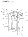
- a typical mold system 100 is comprised of two main mold halves 101A and 101B, two top block halves 102A and 102B, and two back plates 103A and 103B.
- Main mold half 101A is affixed to back plate 103A which in turn is mounted within an extrusion blow-molding machine.
- Top block half 102A is affixed atop main mold half 101A by machine bolts 104 through screw-holes 117 such that top block parting face 105 is aligned with main mold parting face 106.
- the opposing main mold and top block halves are similarly assembled, with further attention that the matching mold halves and top blocks mate properly to each other.
- Reservoir cavity 107 is formed by the mating of the mold halves such that container 200 may be formed therein.
- Container 200 includes reservoir portion 201 and neck portion 202.
- the neck portion includes helical threading 203 therearound.
- the mating top block halves form a thread cavity 108 for forming the container neck threading 203 therein.
- Each top block halve comprises base portion 110, a neck finish insert 111, a shear steel 118, and a master seal 119.
- the neck finish inserts, shear steels and master seals are removable from the top block halves for interchangeability and replacement.
- top block parting face 105 After assembly and alignment, top block parting face 105 must be precisely aligned with main mold parting face 106 to ensure proper molding and minimal mold wear. In order to accomplish this, top plate depth 112, measured from back mounting surface 113 of the back plate 103A to top block parting face 105, must be equal to main mold depth 114, equivalently measured. Further, the parting faces must each be held parallel to the back plate.
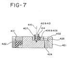
- movable aluminum heel 402 is attached to aluminum top block base 401 within longitudinal groove 403.
- the movable heel includes two longitudinal guide-slots 404 and is held within the groove by two heel mounting shoulder screws 405 which allow longitudinal translation of the heel within the groove.
- the forward face 406 of the movable heel engages rotatable eccentric cam 407 at cylindrical cam surface 408.
- the cam includes through-hole 412 and is affixed to base 401 by cam mounting shoulder screw 413. Loosening of screw 413 allows rotation of the cam, while tightening locks the cam to deny such.
- the cam is adapted such that a wrench may engage external hex feature 414 while a hex driver may engage screw 413. This allows the properly rotated cam to be held in position by a wrench while the screw is tightened, to avoid unintended rotation from the torque of tightening the screw.
- the cylindrical cam surface 408 is eccentric about cam axis 415, so that the distance from the axis to the cam surface ,or the cam throw, varies about the axis. Rotation of the cam about the axis causes more or less throw by the cam and longitudinally moves the point of engagement of the heel's forward face accordingly. This simultaneously allows longitudinal translation of the heel. Such longitudinal translation causes a variation in the top block depth 420, measured from the heel's tail face 421, transverse the top block, to the parting face 422.
- Screw-holes 423 and 424 are positioned in a standard mounting-hole pattern through the base 401 to allow mounting to a standard main mold half.
- Screw-slot 425 is longitudinally positioned through the heel 402 and about screw-hole 424 to allow a mounting screw to pass through and affix the heel and base simultaneously to a standard main mold half.
- the present Invention top block and associated top block components 111, 118, 119 may be affixed and properly aligned to the main mold half 101A, with far more tolerance of the actual main mold depth 114.
- mounting screws are positioned through forward screw-holes 423 and into the main mold half 101A.
- the main mold parting face 106 and present top block parting face 422 are aligned as required, then the mounting screws are tightened.
- Cam mounting shoulder screw 413 is loosened and the cam 407 is rotated until the heel's tail face 421 seats snugly against the forward mounting face 115 of the back plate 103A.
- the cam mounting shoulder screw is now tightened and a mounting screw is positioned through screw-slot 425 and screw-hole 424 and tightened to secure the aligned assembly.
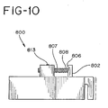
- a second adjustable top block 800 according to the invention is presented in which the cam is a threaded lead-screw 807.
- the lead-screw is adapted with hex socket 814 to accept a hex driver.
- Locking screw 813 must be loosened to allow rotation of the lead-screw or tightened to deny such rotation. Rotation of the lead-screw varies the longitudinal position of the lead-screw's tail end 808 which engages the forward face 806 of the movable heel 802.
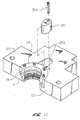
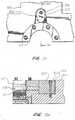
- a third embodiment of the invention is shown in Figs. 12-13. It includes a rotatable cam 507 which bears against the neck finish components 111, 118, 119, thereby allowing the parting faces of these components to be aligned with the parting face 522 of the top block base 501 as well as the parting face of the main mold half 101A with which they are associated.
- the top block base 501 in this embodiment is provided with a cavity 502 in which the cam 507 is positioned.
- the cavity 502 adjoins the cavity in which the neck finish components are mounted, and is located along the center line of the top block base 501.
- the neck finish components include sets of holes which are aligned with corresponding threaded openings (not shown) in the top block base.
- Allen cap screws may be used for securing the neck finish components to the base.
- the cam 507 bears against the rear surfaces of the components.
- the neck finish components may be moved several thousandths of an inch with respect to the base by rotation of the cam, which is sufficient to ensure proper alignment.
- An Allen cap screw 504 may be employed to secure the cam to the top block base 501.
- the assembly shown in Figs. 4-7 may be modified to include the cam 507.
- Figs. 14-16 show a fourth embodiment of the invention.
- This is a highly preferred embodiment as it allows the top block assembly to be correctly aligned with the main mold and prevents shifting of the top block assemblies along the parting plane between mold halves. Such shifting can be attributable to factors such as mold face or back plate irregularities, or wear on the main mold leader pins and bushings.
- the neck finish components are incorrectly aligned with each other and/or the blow pin, the neck finishes of the plastic containers produced by the mold cannot be effectively capped, and leakage will be a problem. Specifically, if the shear steels are not satisfactorily aligned, the opening in the neck finish will not be round, and the annular valve of a cap applied thereto will not provide a leakproof seal.
- the assembly shown in Figs. 14-16 ensures that all neck finish components in both mold halves will be properly aligned with each other each time the mold closes.
- the shear steels are accordingly able to trim flash in a precise manner, providing a smooth finish capable of forming a good seal with a ring-shaped valve member of a cap. If the neck finish blocks are of the types which include threads, the thread formed on each half of the container neck will be positioned correctly, allowing the corresponding threads of a cap to properly engage those on the container neck.
- a top block assembly having the above-described capabilities includes an aluminum top block base 601, a movable heel 602 similar to the heel 402 shown in Figs. 4-7, and a cam assembly 603 including a rotatable cam 607 which is substantially identical to that shown in Figs. 4-7.
- the heel is preferably made from aluminum bronze or stainless steel, though anodized aluminum will perform satisfactorily.
- the cam assembly and heel allow the parting plane of the top block base 601 and neck finish components 111, 118, 119 to be aligned with the parting planes of the main mold half 101A to which they are mounted. As the structure and operation of the heel and cam assembly are described in detail above with respect to Figs. 4-7, it is unnecessary to repeat it with respect to the present embodiment.
- the top block base 601 includes a face portion including a pair of flash pockets 604 on opposite sides of the neck finish components, one of which is shown In Fig. 16.
- the outer edge of each flash pocket adjoins an elongate, vertically extending protrusion 605.
- This protrusion is substantially triangular in cross section, and is referred to as a pinch-off.
- the portions of the top block base 601 outside each pinch-off are known as the tonnage pad sections.
- a male alignment pin 608 is secured to each of the tonnage pad sections of one top block base.
- Each pin may be made from case hardened steel.
- the ends of the pins are preferably rounded.
- Each pin 608 is positioned within a steel bushing 609, as shown in Fig. 15.
- the bushing is located in a horizontal bore 610 extending into the tonnage pad section.
- a second, threaded bore 611 extends vertically into the top block base 601, and intersects the bore 610.
- a set screw 612 is positioned within the threaded bore 611, and maintains the bushing and set screw in position. Removal of the set screw allows the bushing and pin to be replaced when worn or damaged.
- the set screw shown is accessible with an Allen wrench.
- Each of the tonnage pad sections of the opposite top block base 601A includes a bore 610A and bushing 609A.
- a second threaded bore 611A intersects this bore, and contains a second set screw 612A which engages the bushing.
- the bushing contains no alignment pin.
- Each bushing 609A is aligned with a pin 608 of the opposing top block base.
- the tolerance between each pin 608 and bushing is preferably between .0005-.002 inches for a one gallon mold. The closing of the mold causes the pins to enter the respective bushings. As the tolerances between pin and bushing diameters are small, there is little opportunity for either top block base to shift in any direction along the parting plane between mold halves.
- the above-described assembly ensures precise alignment of the neck finish components in all three directions: vertically, horizontally and translationally. Translational alignment is provided by the cam assemblies 603, 603A of the respective top block bases; vertical and horizontal alignment is provided by the pins and bushings.
- the ends of the respective alignment pins are rounded to facilitate their entry into the respective bushings. Once the pins are within the bushings, any shifting of the top block bases which might otherwise occur is prevented.
- the dimensions of the various components may vary depending upon the sizes of the main molds and associated top block bases.
- the pins for the top block base of a one gallon mold may be between about 1/4 and 5/16 of an inch in length.
- the bores defined by the bushings are longer so that the pins to not engage an end wall.
- the diameters of the pins may be about 5/16 of an inch.
- Tapered bins and bushings may be employed, and have the advantage of providing a centering function.
- the possibility of top block base shifting may be further reduced or even eliminated in this manner.
- top block bases may, for example, include integrally formed protrusions and slots similar to the removable pins and bushings described above. While each pin or protrusion is preferably positionable in a bore which is circular in cross section, other pin and bore configurations could be employed to accomplish the desired prevention of shifting of the top block bases horizontally and/or vertically along the parting plane of the mold.
- the alignment means described herein may be incorporated in any of the top block bodies described above, though the assembly shown in Figs. 14-16 is highly preferred.
Landscapes
- Engineering & Computer Science (AREA)
- Mechanical Engineering (AREA)
- Manufacturing & Machinery (AREA)
- Moulds For Moulding Plastics Or The Like (AREA)
Applications Claiming Priority (2)
| Application Number | Priority Date | Filing Date | Title |
|---|---|---|---|
| US748431 | 1996-11-13 | ||
| US08/748,431 US5776518A (en) | 1995-05-16 | 1996-11-13 | Bottle mold and adjustable top block assembly and top block alignment members |
Publications (3)
| Publication Number | Publication Date |
|---|---|
| EP0847846A2 true EP0847846A2 (de) | 1998-06-17 |
| EP0847846A3 EP0847846A3 (de) | 1998-09-23 |
| EP0847846B1 EP0847846B1 (de) | 2003-04-02 |
Family
ID=25009416
Family Applications (1)
| Application Number | Title | Priority Date | Filing Date |
|---|---|---|---|
| EP96120987A Expired - Lifetime EP0847846B1 (de) | 1996-11-13 | 1996-12-30 | Flaschenform mit einstellbarer Oberformanordnung und Ausrichtungsteile für eine Oberformanordnung |
Country Status (4)
| Country | Link |
|---|---|
| US (1) | US5776518A (de) |
| EP (1) | EP0847846B1 (de) |
| CA (1) | CA2194122C (de) |
| DE (1) | DE69627162T2 (de) |
Cited By (2)
| Publication number | Priority date | Publication date | Assignee | Title |
|---|---|---|---|---|
| EP1332862A3 (de) * | 2002-02-05 | 2005-03-23 | Ultraseal Technologies Corporation | Verfahren und Vorrichtung zur Positionierung der Oberformanordnung sowie Elemente für den Behälterhals in einer Blasformeinrichtung |
| IT201700093124A1 (it) * | 2017-08-10 | 2019-02-10 | Orvim Srl | Colletto e parti complementari fatti in materiali compositi e materiali plastici per macchine di stampi di soffiaggio |
Families Citing this family (19)
| Publication number | Priority date | Publication date | Assignee | Title |
|---|---|---|---|---|
| US7229587B2 (en) * | 2003-04-03 | 2007-06-12 | Custom - Pak, Inc. | Blow molded container having holes therein and method and apparatus for facilitating the creation thereof |
| US7214341B2 (en) * | 2004-01-30 | 2007-05-08 | Owens-Illinois Prescription Products Inc. | Method of injection molding a preform including a radially extending element |
| US20060177536A1 (en) * | 2005-02-08 | 2006-08-10 | Boden Christian S | Apparatus for blow molding |
| US20060177537A1 (en) * | 2005-02-08 | 2006-08-10 | Boden Christian S | Apparatus for blow molding |
| US7270529B2 (en) * | 2005-02-08 | 2007-09-18 | Uniloy Milacron Inc. | Apparatus for blow molding |
| US20060182841A1 (en) * | 2005-02-16 | 2006-08-17 | Rick Rodriguez | Apparatus for blow molding |
| US20060255513A1 (en) * | 2005-05-11 | 2006-11-16 | Graham Packaging Company, L.P. | Mold gap seal |
| US7713055B2 (en) * | 2005-10-18 | 2010-05-11 | Milacron Llc | Blow mold assembly |
| CN100553924C (zh) * | 2006-01-18 | 2009-10-28 | 鸿富锦精密工业(深圳)有限公司 | 光学元件成型模具 |
| US7713054B2 (en) * | 2007-12-12 | 2010-05-11 | Husky Injection Molding Systems Ltd. | Split mold insert and a mold incorporating same |
| CN101298355B (zh) * | 2008-06-04 | 2010-10-06 | 常熟市伟恒模具铸造有限公司 | 制作玻璃容器用的模具 |
| US8641955B2 (en) * | 2008-08-08 | 2014-02-04 | Gauthier Biomedical Inc. | Method for forming a molded component for an item |
| US10000405B2 (en) | 2010-06-29 | 2018-06-19 | Owens-Brockway Glass Container Inc. | Stelvin/cork glass wine bottles |
| US9486942B1 (en) * | 2013-03-25 | 2016-11-08 | Stampede Die Corp. | Mold interlocks |
| US10703021B2 (en) * | 2017-06-06 | 2020-07-07 | R&D Tool & Engineering Co. | Cavity mold alignment system for blow mold tooling |
| CN107902873A (zh) * | 2017-12-19 | 2018-04-13 | 常熟市伟恒模具铸造有限公司 | 头颈镶嵌式成模 |
| WO2020247795A1 (en) * | 2019-06-07 | 2020-12-10 | Tpi Composites, Inc. | Mold precision pins for component location during fabrication of wind turbine blades |
| USD1103773S1 (en) | 2023-06-07 | 2025-12-02 | Hattab Global Corp. | Connectable beverage bottle |
| US12589544B2 (en) * | 2022-07-14 | 2026-03-31 | Hattab Global Corp. | Three-piece mold device, system, and method for manufacturing of connectable beverage bottle |
Family Cites Families (24)
| Publication number | Priority date | Publication date | Assignee | Title |
|---|---|---|---|---|
| US3264684A (en) * | 1963-10-08 | 1966-08-09 | Ernest P Moslo | Neck ring mold |
| US3354509A (en) * | 1965-06-01 | 1967-11-28 | Diversified Prod | Barbell mold |
| DE1936648C3 (de) * | 1969-07-18 | 1975-07-24 | Gerhard 7161 Laufen Hansen | Verfahren und Vorrichtung zum Herstellen von mit fließfähigem Gut gefüllten Kunststoffbehältern |
| US3868202A (en) * | 1971-12-27 | 1975-02-25 | Emery I Valyi | Apparatus for the production of composite containers |
| US3807928A (en) * | 1972-03-24 | 1974-04-30 | Monsanto Co | Blow mold improvements |
| US3941539A (en) * | 1972-12-05 | 1976-03-02 | Continental Can Company, Inc. | Injection blow molding apparatus and method |
| US3892829A (en) * | 1973-10-03 | 1975-07-01 | Owens Illinois Inc | Method of making blown plastic articles |
| US4076484A (en) * | 1975-11-10 | 1978-02-28 | Hercules Incorporated | Injection-blow molding machine having non-splitting injection and blow molds |
| US4832592A (en) * | 1976-07-23 | 1989-05-23 | Saumsiegle Robert W | Hollow article forming apparatus |
| US4299371A (en) * | 1979-02-21 | 1981-11-10 | Emhart Industries, Inc. | Neck ring assembly |
| US4254933A (en) * | 1979-12-26 | 1981-03-10 | Netto Eduardo D L C | Mold for injection molding |
| US4285658A (en) * | 1980-02-01 | 1981-08-25 | Cincinnati Milacron Inc. | Self-centering blow mold |
| US4352652A (en) * | 1981-03-23 | 1982-10-05 | Charlotte Pipe And Foundry Company | Apparatus for molding plastic pipe fitting with internal groove therein |
| US4382769A (en) * | 1981-03-31 | 1983-05-10 | Hercules Incorporated | Container forming apparatus |
| US4818213A (en) * | 1982-04-12 | 1989-04-04 | Roy Siegfried S | Injection blow molding |
| DE3623099C3 (de) * | 1986-07-09 | 1998-08-13 | Spoetzl Markus Dipl Ing Fh | Blasformmaschine |
| EP0297196A1 (de) * | 1987-04-03 | 1989-01-04 | Chell Snc | Hohlform zur Herstellung von plastischen Gegenständen, die verschiedene Höhen und Mundstücke haben |
| CA1328550C (en) * | 1988-09-19 | 1994-04-19 | Yoshinori Umezawa | Method of fabricating pipe units |
| GB2238974A (en) * | 1989-12-13 | 1991-06-19 | William Douglas Lamb | Securing neck inserts into moulds for plastics bottles |
| US5332384A (en) * | 1992-07-29 | 1994-07-26 | Gerhard Abramat | Blow mold guide pin and alignment device |
| US5474438A (en) * | 1993-10-14 | 1995-12-12 | Walker, Jr.; John T. | Adjustable back plate for a mold |
| US5589204A (en) * | 1995-05-16 | 1996-12-31 | Wohlgemuth; Emanuel E. | Bottle mold with adjustable neck block |
| US5629032A (en) * | 1995-08-25 | 1997-05-13 | Pari Industries, Inc. | Blow-molding apparatus |
| US5585121A (en) * | 1995-11-16 | 1996-12-17 | Allied Tool, Inc. | Adjustable shear plate for blow molding machine |
-
1996
- 1996-11-13 US US08/748,431 patent/US5776518A/en not_active Expired - Lifetime
- 1996-12-30 CA CA002194122A patent/CA2194122C/en not_active Expired - Fee Related
- 1996-12-30 EP EP96120987A patent/EP0847846B1/de not_active Expired - Lifetime
- 1996-12-30 DE DE69627162T patent/DE69627162T2/de not_active Expired - Fee Related
Non-Patent Citations (1)
| Title |
|---|
| None |
Cited By (2)
| Publication number | Priority date | Publication date | Assignee | Title |
|---|---|---|---|---|
| EP1332862A3 (de) * | 2002-02-05 | 2005-03-23 | Ultraseal Technologies Corporation | Verfahren und Vorrichtung zur Positionierung der Oberformanordnung sowie Elemente für den Behälterhals in einer Blasformeinrichtung |
| IT201700093124A1 (it) * | 2017-08-10 | 2019-02-10 | Orvim Srl | Colletto e parti complementari fatti in materiali compositi e materiali plastici per macchine di stampi di soffiaggio |
Also Published As
| Publication number | Publication date |
|---|---|
| EP0847846A3 (de) | 1998-09-23 |
| DE69627162T2 (de) | 2003-11-13 |
| DE69627162D1 (de) | 2003-05-08 |
| CA2194122C (en) | 2000-02-15 |
| EP0847846B1 (de) | 2003-04-02 |
| US5776518A (en) | 1998-07-07 |
| CA2194122A1 (en) | 1998-05-14 |
Similar Documents
| Publication | Publication Date | Title |
|---|---|---|
| US5776518A (en) | Bottle mold and adjustable top block assembly and top block alignment members | |
| DE10033412B4 (de) | Vorrichtung zur Blasformung von Behältern | |
| US7935280B2 (en) | Core locking assembly and method for orientation of asymmetric tooling | |
| EP1189740B1 (de) | Vorrichtung zur blasformung von behältern | |
| US5803676A (en) | Method and tool for repairing damaged threads | |
| US20060145369A1 (en) | Non-optical multi-piece core assembly for rapid tool change | |
| US5589204A (en) | Bottle mold with adjustable neck block | |
| US5795598A (en) | Assembly for inflating a parison and forming the neck of a plastic bottle | |
| US6939500B2 (en) | Method and apparatus for eliminating a parting line witness mark from a molded part | |
| US20060145370A1 (en) | Optical tool assembly | |
| US6966764B2 (en) | Method and apparatus for positioning a top block assembly and neck finish components of a blow molding machine | |
| US7258538B2 (en) | Apparatus for blow molding | |
| EP0256693A2 (de) | Formsatz für Kunststoff-Formmaschinen | |
| US5647114A (en) | Method of providing a barrier to substantially block the flow of liquid in a mold insert | |
| US6824732B2 (en) | Blow pin assembly | |
| US5894024A (en) | Adjustable, pinch-off neck assembly | |
| US4732514A (en) | Device for use in reshaping the gate of a metal mould for plastic injection moulding | |
| US20090155400A1 (en) | Apparatus for Blow Molding | |
| CN219769069U (zh) | Pet中空吹塑模分模结构 | |
| US20060165839A1 (en) | Method and apparatus for making blown containers with round neck openings | |
| CN218312204U (zh) | 一种玻璃模具加工用工装夹具 | |
| US20250340000A1 (en) | Gate insert for injection molding | |
| KR910007779Y1 (ko) | 타이어 가류금형내의 문자변경 및 공기 누출장치 | |
| JPH11925A (ja) | 成形用金型 | |
| JP2002187174A (ja) | 射出成形用金型 |
Legal Events
| Date | Code | Title | Description |
|---|---|---|---|
| PUAI | Public reference made under article 153(3) epc to a published international application that has entered the european phase |
Free format text: ORIGINAL CODE: 0009012 |
|
| AK | Designated contracting states |
Kind code of ref document: A2 Designated state(s): DE FR GB IE |
|
| AX | Request for extension of the european patent |
Free format text: AL;LT;LV;RO;SI |
|
| PUAL | Search report despatched |
Free format text: ORIGINAL CODE: 0009013 |
|
| AK | Designated contracting states |
Kind code of ref document: A3 Designated state(s): AT BE CH DE DK ES FI FR GB GR IE IT LI LU MC NL PT SE |
|
| AX | Request for extension of the european patent |
Free format text: AL;LT;LV;RO;SI |
|
| 17P | Request for examination filed |
Effective date: 19990203 |
|
| AKX | Designation fees paid |
Free format text: DE FR GB IE |
|
| RBV | Designated contracting states (corrected) |
Designated state(s): DE FR GB IE |
|
| 17Q | First examination report despatched |
Effective date: 20001212 |
|
| GRAG | Despatch of communication of intention to grant |
Free format text: ORIGINAL CODE: EPIDOS AGRA |
|
| GRAG | Despatch of communication of intention to grant |
Free format text: ORIGINAL CODE: EPIDOS AGRA |
|
| GRAH | Despatch of communication of intention to grant a patent |
Free format text: ORIGINAL CODE: EPIDOS IGRA |
|
| RAP1 | Party data changed (applicant data changed or rights of an application transferred) |
Owner name: ULTRASEAL TECHNOLOGIES CORPORATION |
|
| GRAH | Despatch of communication of intention to grant a patent |
Free format text: ORIGINAL CODE: EPIDOS IGRA |
|
| GRAH | Despatch of communication of intention to grant a patent |
Free format text: ORIGINAL CODE: EPIDOS IGRA |
|
| GRAH | Despatch of communication of intention to grant a patent |
Free format text: ORIGINAL CODE: EPIDOS IGRA |
|
| GRAA | (expected) grant |
Free format text: ORIGINAL CODE: 0009210 |
|
| AK | Designated contracting states |
Designated state(s): DE FR GB IE |
|
| REG | Reference to a national code |
Ref country code: GB Ref legal event code: FG4D |
|
| REG | Reference to a national code |
Ref country code: IE Ref legal event code: FG4D |
|
| REF | Corresponds to: |
Ref document number: 69627162 Country of ref document: DE Date of ref document: 20030508 Kind code of ref document: P |
|
| ET | Fr: translation filed | ||
| PLBE | No opposition filed within time limit |
Free format text: ORIGINAL CODE: 0009261 |
|
| STAA | Information on the status of an ep patent application or granted ep patent |
Free format text: STATUS: NO OPPOSITION FILED WITHIN TIME LIMIT |
|
| 26N | No opposition filed |
Effective date: 20040105 |
|
| PGFP | Annual fee paid to national office [announced via postgrant information from national office to epo] |
Ref country code: FR Payment date: 20061208 Year of fee payment: 11 |
|
| PGFP | Annual fee paid to national office [announced via postgrant information from national office to epo] |
Ref country code: IE Payment date: 20061213 Year of fee payment: 11 |
|
| PGFP | Annual fee paid to national office [announced via postgrant information from national office to epo] |
Ref country code: GB Payment date: 20061227 Year of fee payment: 11 |
|
| PGFP | Annual fee paid to national office [announced via postgrant information from national office to epo] |
Ref country code: DE Payment date: 20061229 Year of fee payment: 11 |
|
| GBPC | Gb: european patent ceased through non-payment of renewal fee |
Effective date: 20071230 |
|
| REG | Reference to a national code |
Ref country code: IE Ref legal event code: MM4A |
|
| PG25 | Lapsed in a contracting state [announced via postgrant information from national office to epo] |
Ref country code: IE Free format text: LAPSE BECAUSE OF NON-PAYMENT OF DUE FEES Effective date: 20071231 Ref country code: DE Free format text: LAPSE BECAUSE OF NON-PAYMENT OF DUE FEES Effective date: 20080701 |
|
| REG | Reference to a national code |
Ref country code: FR Ref legal event code: ST Effective date: 20081020 |
|
| PG25 | Lapsed in a contracting state [announced via postgrant information from national office to epo] |
Ref country code: GB Free format text: LAPSE BECAUSE OF NON-PAYMENT OF DUE FEES Effective date: 20071230 |
|
| PG25 | Lapsed in a contracting state [announced via postgrant information from national office to epo] |
Ref country code: FR Free format text: LAPSE BECAUSE OF NON-PAYMENT OF DUE FEES Effective date: 20071231 |