EP0848105A2 - Procédé et appareil pour mesurer des distances dans la zone de la caisse de tête d'une machine à papier - Google Patents
Procédé et appareil pour mesurer des distances dans la zone de la caisse de tête d'une machine à papier Download PDFInfo
- Publication number
- EP0848105A2 EP0848105A2 EP97119141A EP97119141A EP0848105A2 EP 0848105 A2 EP0848105 A2 EP 0848105A2 EP 97119141 A EP97119141 A EP 97119141A EP 97119141 A EP97119141 A EP 97119141A EP 0848105 A2 EP0848105 A2 EP 0848105A2
- Authority
- EP
- European Patent Office
- Prior art keywords
- magnetic field
- measuring device
- headbox
- lip
- lips
- Prior art date
- Legal status (The legal status is an assumption and is not a legal conclusion. Google has not performed a legal analysis and makes no representation as to the accuracy of the status listed.)
- Granted
Links
Images
Classifications
-
- D—TEXTILES; PAPER
- D21—PAPER-MAKING; PRODUCTION OF CELLULOSE
- D21F—PAPER-MAKING MACHINES; METHODS OF PRODUCING PAPER THEREON
- D21F1/00—Wet end of machines for making continuous webs of paper
- D21F1/02—Head boxes of Fourdrinier machines
-
- D—TEXTILES; PAPER
- D21—PAPER-MAKING; PRODUCTION OF CELLULOSE
- D21F—PAPER-MAKING MACHINES; METHODS OF PRODUCING PAPER THEREON
- D21F1/00—Wet end of machines for making continuous webs of paper
- D21F1/02—Head boxes of Fourdrinier machines
- D21F1/028—Details of the nozzle section
Definitions
- the invention relates to a method and a device for measuring Clearances in the area of the headbox of a paper machine.
- the aim of the invention is therefore to provide a measurement method that the Measures the outlet gap directly with the best accuracy.
- the invention is therefore characterized in that magnetic Constant fields are generated in the area of the headbox outlet gap, their thickness measured and from this the distance between the individual lips is determined. This enables the consistencies in the constant part of the paper machine be precisely determined, which creates the conditions for the exact control of a multi-layer headbox (top layer, Intermediate layer, back layer) is given. The amount of substance of each Layers can be set precisely in the area of the headbox will.
- An advantageous development of the invention is characterized in that that the magnetic field is generated by a permanent magnet.
- Conventional inductive distance sensors or eddy current sensors cannot penetrate the stainless steel walls.
- a favorable embodiment of the invention is characterized in that that the measurement of the magnetic field is carried out by a Hall generator. These are due to the small mechanical dimensions especially suitable for installation in thin lips.
- a favorable further development of the invention is characterized in that that a linearization of the measurement result by subsequent connection on Signal output of the magnetic field sensor from nonlinear elements with non-linear characteristic is reversed to the magnetic field characteristic. As a result, no linearization of the magnetic field is necessary.
- An advantageous embodiment of the invention is characterized in that that nonlinear signals from a transducer into a via a data table linear signal can be converted.
- This data table can be special simply be adapted to the respective magnetic field characteristics. Also possible non-linearities of the Hall generator or the signal processing can be taken into account in this way.
- An alternative embodiment of the invention is characterized in that that nonlinear signals from a transducer into a via a data table targeted non-linear signal can be converted. That has e.g. the advantage, that small distances can be detected with greater accuracy, larger distances with less accuracy.
- the relative accuracy (Resolution / current signal level) could e.g. B. over the entire measuring range be kept constant.
- the invention also relates to a measuring device for determining distances in the area of the headbox of a paper machine. she is characterized in that in one of the two, the distance determining elements a magnetic field generator for a magnetic Same field and on the second of the two, determining the distance Elements a magnetic field meter is provided. Such Measuring device can be particularly easily in the thin lips of a Headbox are housed.
- a favorable further development of the invention is characterized in that that a permanent magnet is provided as the magnetic field source, wherein alternatively, a current coil can also be provided.
- the permanent magnet needs no electrical supply voltage, needed therefore no cable connection to the other parts of the measuring arrangement.
- a current coil can be a particularly strong one and also at extreme temperature fluctuations generate a constant magnetic field.
- An advantageous embodiment of the invention is characterized in that that a Hall generator is provided as a magnetic field measuring device. This is due to its small mechanical dimensions, it is particularly easy to To house the lips of the headbox.
- An advantageous development of the invention is characterized in that that in a two-layer headbox with a central lip, the magnetic field source, especially the permanent magnet, in the middle lip and in everyone outer lip (upper and lower lip) provided a magnetic field meter are.
- the gap between the upper lip can also be particularly good and middle lip and between the middle lip and lower lip will.
- a particularly favorable development of the invention is characterized in that in a multi-layer headbox with several Intermediate lips the magnetic field sources, especially the permanent magnets, are staggered in the intermediate lips and in each outer lip (upper and lower lip) for each magnetic field Pair of magnetic field meters is provided. With this move The position of the individual intermediate lips can be arranged determine exactly between the upper and lower lip and thus also the Gap between the intermediate lips from the differences in the distances to calculate. So all are for the determination of the individual material flows Column recorded.
- An advantageous embodiment of the invention is characterized in that that the magnets are designed such that they have a linear magnetic field produce.
- the signal from the magnetic field detectors can then without further processing can be used as a measurement signal.
- a favorable further development of the invention is characterized in that that magnetic field meters are connected to a microprocessor.
- the signals from the transducer can thus be particularly cheap into the linear or non-linear ones required for further processing Convert signals.
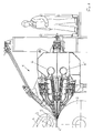
- Fig. 1 shows a section through a two-layer headbox Tissue paper machine
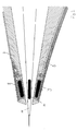
- Fig. 2 the lips with the built-in measuring devices in detail
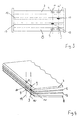
- Fig. 3 the installation situation with a three-layer Headbox
- Fig. 4 is an axionometric view of Fig. 3.
- the paper web is here formed between two rollers 2, 3 are covered with sieves 4, 4 '. Between them around the rollers 2, 3 running sieves 4, 4 'there is a gap 5 into which the headbox 1 is injected via feed lines 6, 6 'injected suspension.
- the speed of the sieve belts 4, 4 'and thus the required The speed of the suspension injected into the gap 5 can up to about 2000 m / min. be.
- the area of the suspension exit into the gap 5 between the sieves 4, 4 'on the rollers 2, 3 is shown in detail in Fig. 2.
- the magnetic field transmitter 10 is installed in the intermediate lip 11.
- the Magnetic field of the transmitter 10 has a position-dependent intensity.
- the signal of the magnetic field receiver 9 corresponds to the received one Magnetic field and is therefore also from the position, in particular from the Distance to the magnetic field transmitter 10 depends. So it can Signal of the magnetic field receiver 9 as a measure of the distance of the Intermediate lip 11 to the upper lip 7 or lower lip 8 can be used. In usually exists between the distance from the transmitter 10 to Receiver 9 no linear relationship, but there is a clear one Relationship in the form that a particular signal a certain magnetic field strength and thus corresponds to a certain distance.
- This linearization produces e.g. via a data table a value for the from the respective magnetic field receiver signal actual distance.
- the output can be on a display, or also as a standardized current signal e.g. 4 ... 20 milliamps.
- the current signal is particularly suitable for further processing of the signal in one Process control system.
- Fig. 3 is the view from the screen section on the lips of a three-layer headbox.
- two measuring arrangements 14, 14 ' are sufficient offset far to the side so that there is no mutual interference more exists.
- the left measuring arrangement 14 measures the position of the lower intermediate lip 13, the right measuring arrangement 14 'the position of the upper intermediate lip 12. From these signals can by difference also the distance between the two intermediate lips 12, 13 be determined.
- the measuring arrangements 14, 14 ' are analogous to the measuring arrangement built in a two-layer headbox and consist of two magnetic field receivers 9 and one transmitter 10 each.
- Fig. 4 shows a perspective view of the lips 7, 8, 12, 13 and built-in measuring arrangements 14, 14 'for a three-layer headbox.
Landscapes
- Measurement Of Length, Angles, Or The Like Using Electric Or Magnetic Means (AREA)
- Measuring Magnetic Variables (AREA)
- Controlling Sheets Or Webs (AREA)
Applications Claiming Priority (3)
| Application Number | Priority Date | Filing Date | Title |
|---|---|---|---|
| AT198596 | 1996-11-13 | ||
| AT0198596A AT404848B (de) | 1996-11-13 | 1996-11-13 | Verfahren und einrichtung zur messung von abständen im bereich des stoffauflaufes einer papiermaschine |
| AT1985/96 | 1996-11-13 |
Publications (3)
| Publication Number | Publication Date |
|---|---|
| EP0848105A2 true EP0848105A2 (fr) | 1998-06-17 |
| EP0848105A3 EP0848105A3 (fr) | 1999-01-13 |
| EP0848105B1 EP0848105B1 (fr) | 2002-09-25 |
Family
ID=3525356
Family Applications (1)
| Application Number | Title | Priority Date | Filing Date |
|---|---|---|---|
| EP97119141A Expired - Lifetime EP0848105B1 (fr) | 1996-11-13 | 1997-11-03 | Appareil pour mesurer des distances dans la zone de la caisse de tête d'une machine à papier |
Country Status (9)
| Country | Link |
|---|---|
| US (1) | US6221213B1 (fr) |
| EP (1) | EP0848105B1 (fr) |
| CN (1) | CN1145012C (fr) |
| AT (1) | AT404848B (fr) |
| CA (1) | CA2220838A1 (fr) |
| DE (1) | DE59708318D1 (fr) |
| ES (1) | ES2184018T3 (fr) |
| ID (1) | ID19703A (fr) |
| ZA (1) | ZA9710179B (fr) |
Families Citing this family (2)
| Publication number | Priority date | Publication date | Assignee | Title |
|---|---|---|---|---|
| US8333631B2 (en) * | 2009-02-19 | 2012-12-18 | Cree, Inc. | Methods for combining light emitting devices in a package and packages including combined light emitting devices |
| CN109520408B (zh) * | 2019-01-09 | 2020-10-27 | 谭斌 | 钢筋间距检测设备及钢筋间距测量方法 |
Family Cites Families (8)
| Publication number | Priority date | Publication date | Assignee | Title |
|---|---|---|---|---|
| US3828248A (en) * | 1971-01-14 | 1974-08-06 | G Wennerberg | Apparatus for measuring a predetermined characteristic of moving sheet material which accommodates both tilting and changes in thickness and vertical location of the material |
| DE2409521C3 (de) * | 1974-02-28 | 1979-04-26 | J.M. Voith Gmbh, 7920 Heidenheim | Stoff auflauf für Papiermaschinen |
| DE3107926A1 (de) * | 1981-03-02 | 1982-11-04 | Escher Wyss Gmbh, 7980 Ravensburg | Verfahren zum ausbilden einer mehrlagigen papierbahn in einem doppelsiebformer und doppelsiebformer zur durchfuehrung des verfahrens |
| CA1157304A (fr) * | 1981-09-28 | 1983-11-22 | Consolidated-Bathurst Inc. | Methode et dispositif de controle d'un produit affecte par le dosage |
| SE428809B (sv) * | 1981-12-01 | 1983-07-25 | Karlstad Mekaniska Ab | Sett och anordning for att under drift av en inloppslada eller liknande meldavgivande don for en pappersmaskin erhalla information om storleken av en meltutloppsspalt |
| US4791367A (en) * | 1987-07-15 | 1988-12-13 | Impact Systems, Inc. | Contacting thickness gauge for moving sheet material |
| US4929895A (en) * | 1989-03-22 | 1990-05-29 | Impact Systems, Inc. | Thickness gauge for moving sheet material with inner and outer flexibly mounted bearings |
| FI92437C (fi) * | 1992-06-09 | 1994-11-10 | Tampella Oy Valmet | Magneettinen mittausmenetelmä raon suuruuden ja muodon (profiilin) määräämiseksi |
-
1996
- 1996-11-13 AT AT0198596A patent/AT404848B/de not_active IP Right Cessation
-
1997
- 1997-11-03 DE DE59708318T patent/DE59708318D1/de not_active Expired - Fee Related
- 1997-11-03 EP EP97119141A patent/EP0848105B1/fr not_active Expired - Lifetime
- 1997-11-03 ES ES97119141T patent/ES2184018T3/es not_active Expired - Lifetime
- 1997-11-06 ID IDP973620A patent/ID19703A/id unknown
- 1997-11-12 ZA ZA9710179A patent/ZA9710179B/xx unknown
- 1997-11-12 CA CA002220838A patent/CA2220838A1/fr not_active Abandoned
- 1997-11-13 CN CNB971141584A patent/CN1145012C/zh not_active Expired - Fee Related
- 1997-11-13 US US08/969,691 patent/US6221213B1/en not_active Expired - Fee Related
Also Published As
| Publication number | Publication date |
|---|---|
| AT404848B (de) | 1999-03-25 |
| ID19703A (id) | 1998-07-30 |
| CN1145012C (zh) | 2004-04-07 |
| EP0848105A3 (fr) | 1999-01-13 |
| CN1183545A (zh) | 1998-06-03 |
| CA2220838A1 (fr) | 1998-05-13 |
| ES2184018T3 (es) | 2003-04-01 |
| DE59708318D1 (de) | 2002-10-31 |
| US6221213B1 (en) | 2001-04-24 |
| EP0848105B1 (fr) | 2002-09-25 |
| ATA198596A (de) | 1998-07-15 |
| ZA9710179B (en) | 1998-05-28 |
Similar Documents
| Publication | Publication Date | Title |
|---|---|---|
| DE68924898T2 (de) | System und Verfahren zur Detektion der Quereigenschaften einer sich bewegenden Bahn. | |
| DE3905658A1 (de) | Verfahren und vorrichtung zum messen der feuchte eines gutes | |
| DE2257510A1 (de) | Verfahren und geraet zum messen der spannung eines bands | |
| CH479478A (de) | Verfahren und Vorrichtung zur Überwachung der Bewegung eines Textilfadens | |
| EP1189058A2 (fr) | Procédé et appareil d'inspection d'une pièce à usiner par courants de Foucault | |
| DE3780210T2 (de) | Ultraschallgeschwindigkeitsmessung in einer sich bewegenden papierbahn. | |
| EP0846310B1 (fr) | Procede et dispositif pour mesurer des proprietes magnetiques de materiaux sous forme de feuilles | |
| EP0848105B1 (fr) | Appareil pour mesurer des distances dans la zone de la caisse de tête d'une machine à papier | |
| DE4136527A1 (de) | Vorrichtung und verfahren zur untersuchung eines drahtseils | |
| DE3781372T2 (de) | Geraet zur prozessgekoppelten charakterisierung einer (papier-)bahnbildung. | |
| DE1598592A1 (de) | Verfahren und Anordnung zur Messung des Feuchtigkeitsgehaltes | |
| DE69635353T2 (de) | Verfahren und vorrichtung zur indiktiven messung von physikalischen parametern eines gegenstandes aus metall sowie deren verwendung | |
| EP0814324B1 (fr) | Systèmes d'amplificateur de mesure pour débitmètres électromagnétiques | |
| DE102012201592B3 (de) | Coriolis-Massendurchflussmessgerät | |
| AT391719B (de) | Stoffauflauf-vorrichtung | |
| DE69814351T2 (de) | Gerät zum ermitteln der eigenschaften eines elektrisch leitfähigen objektes | |
| DE2856240A1 (de) | Verfahren zur induktiven durchflussmessung von fluessigkeiten in teilgefuellten rohrleitungen oder offenen kanaelen sowie durchflussmesser zur durchfuehrung des verfahrens | |
| CH690385A5 (de) | Verfahren und Vorrichtung zur Hochgeschwindigkeitsmessung und Kennzeichnung von magnetischen Materialien. | |
| DE2133725A1 (de) | Elektronischer muenzpruefer | |
| DE112006001212B4 (de) | Verfahren und Messgerät zur Messung von Wassergehalt | |
| DE69315340T2 (de) | Magnetisch messverfahren und vorrichtung zur bestimmung von grösse und form eines schlitzes | |
| DE19806121C2 (de) | Vorrichtung zur Ermittlung verschiedener Druckwerte in einem rotierenden System | |
| DE4231314A1 (de) | Garnbruch-detektoreinrichtung | |
| DE102010050026A1 (de) | Magnetisch abtastende Positionsmessvorrichtung | |
| EP0014398A2 (fr) | Dispositif de mesure sans contact d'épaisseurs ou de distances |
Legal Events
| Date | Code | Title | Description |
|---|---|---|---|
| PUAI | Public reference made under article 153(3) epc to a published international application that has entered the european phase |
Free format text: ORIGINAL CODE: 0009012 |
|
| AK | Designated contracting states |
Kind code of ref document: A2 Designated state(s): DE ES FI FR GB IT NL SE |
|
| AX | Request for extension of the european patent |
Free format text: AL;LT;LV;MK;RO;SI |
|
| PUAL | Search report despatched |
Free format text: ORIGINAL CODE: 0009013 |
|
| AK | Designated contracting states |
Kind code of ref document: A3 Designated state(s): AT BE CH DE DK ES FI FR GB GR IE IT LI LU MC NL PT SE |
|
| AX | Request for extension of the european patent |
Free format text: AL;LT;LV;MK;RO;SI |
|
| RHK1 | Main classification (correction) |
Ipc: D21F 1/02 |
|
| 17P | Request for examination filed |
Effective date: 19990614 |
|
| AKX | Designation fees paid |
Free format text: DE ES FI FR GB IT NL SE |
|
| RAP1 | Party data changed (applicant data changed or rights of an application transferred) |
Owner name: ANDRITZ AG |
|
| 17Q | First examination report despatched |
Effective date: 20010518 |
|
| RTI1 | Title (correction) |
Free format text: APPARATUS TO MEASURE DISTANCES IN THE ZONE OF THE HEADBOX IN A PAPER MACHINE |
|
| GRAG | Despatch of communication of intention to grant |
Free format text: ORIGINAL CODE: EPIDOS AGRA |
|
| GRAG | Despatch of communication of intention to grant |
Free format text: ORIGINAL CODE: EPIDOS AGRA |
|
| GRAH | Despatch of communication of intention to grant a patent |
Free format text: ORIGINAL CODE: EPIDOS IGRA |
|
| GRAH | Despatch of communication of intention to grant a patent |
Free format text: ORIGINAL CODE: EPIDOS IGRA |
|
| GRAA | (expected) grant |
Free format text: ORIGINAL CODE: 0009210 |
|
| AK | Designated contracting states |
Kind code of ref document: B1 Designated state(s): DE ES FI FR GB IT NL SE |
|
| REG | Reference to a national code |
Ref country code: GB Ref legal event code: FG4D Free format text: NOT ENGLISH |
|
| REF | Corresponds to: |
Ref document number: 59708318 Country of ref document: DE Date of ref document: 20021031 |
|
| GBT | Gb: translation of ep patent filed (gb section 77(6)(a)/1977) |
Effective date: 20021206 |
|
| REG | Reference to a national code |
Ref country code: ES Ref legal event code: FG2A Ref document number: 2184018 Country of ref document: ES Kind code of ref document: T3 |
|
| ET | Fr: translation filed | ||
| PLBE | No opposition filed within time limit |
Free format text: ORIGINAL CODE: 0009261 |
|
| STAA | Information on the status of an ep patent application or granted ep patent |
Free format text: STATUS: NO OPPOSITION FILED WITHIN TIME LIMIT |
|
| 26N | No opposition filed |
Effective date: 20030626 |
|
| PGFP | Annual fee paid to national office [announced via postgrant information from national office to epo] |
Ref country code: GB Payment date: 20051024 Year of fee payment: 9 |
|
| PGFP | Annual fee paid to national office [announced via postgrant information from national office to epo] |
Ref country code: FR Payment date: 20051110 Year of fee payment: 9 Ref country code: DE Payment date: 20051110 Year of fee payment: 9 |
|
| PGFP | Annual fee paid to national office [announced via postgrant information from national office to epo] |
Ref country code: SE Payment date: 20051114 Year of fee payment: 9 Ref country code: NL Payment date: 20051114 Year of fee payment: 9 |
|
| PGFP | Annual fee paid to national office [announced via postgrant information from national office to epo] |
Ref country code: FI Payment date: 20051115 Year of fee payment: 9 |
|
| PGFP | Annual fee paid to national office [announced via postgrant information from national office to epo] |
Ref country code: ES Payment date: 20051121 Year of fee payment: 9 |
|
| PG25 | Lapsed in a contracting state [announced via postgrant information from national office to epo] |
Ref country code: FI Free format text: LAPSE BECAUSE OF NON-PAYMENT OF DUE FEES Effective date: 20061103 |
|
| PG25 | Lapsed in a contracting state [announced via postgrant information from national office to epo] |
Ref country code: SE Free format text: LAPSE BECAUSE OF NON-PAYMENT OF DUE FEES Effective date: 20061104 |
|
| PGFP | Annual fee paid to national office [announced via postgrant information from national office to epo] |
Ref country code: IT Payment date: 20061130 Year of fee payment: 10 |
|
| PG25 | Lapsed in a contracting state [announced via postgrant information from national office to epo] |
Ref country code: NL Free format text: LAPSE BECAUSE OF NON-PAYMENT OF DUE FEES Effective date: 20070601 Ref country code: DE Free format text: LAPSE BECAUSE OF NON-PAYMENT OF DUE FEES Effective date: 20070601 |
|
| EUG | Se: european patent has lapsed | ||
| GBPC | Gb: european patent ceased through non-payment of renewal fee |
Effective date: 20061103 |
|
| NLV4 | Nl: lapsed or anulled due to non-payment of the annual fee |
Effective date: 20070601 |
|
| REG | Reference to a national code |
Ref country code: FR Ref legal event code: ST Effective date: 20070731 |
|
| PG25 | Lapsed in a contracting state [announced via postgrant information from national office to epo] |
Ref country code: GB Free format text: LAPSE BECAUSE OF NON-PAYMENT OF DUE FEES Effective date: 20061103 |
|
| REG | Reference to a national code |
Ref country code: ES Ref legal event code: FD2A Effective date: 20061104 |
|
| PG25 | Lapsed in a contracting state [announced via postgrant information from national office to epo] |
Ref country code: FR Free format text: LAPSE BECAUSE OF NON-PAYMENT OF DUE FEES Effective date: 20061130 Ref country code: ES Free format text: LAPSE BECAUSE OF NON-PAYMENT OF DUE FEES Effective date: 20061104 |
|
| PG25 | Lapsed in a contracting state [announced via postgrant information from national office to epo] |
Ref country code: IT Free format text: LAPSE BECAUSE OF NON-PAYMENT OF DUE FEES Effective date: 20071103 |