EP0848115B1 - Appareil de cuisine avec un dispositif de sécurité pour le réseau d'alimentation - Google Patents
Appareil de cuisine avec un dispositif de sécurité pour le réseau d'alimentation Download PDFInfo
- Publication number
- EP0848115B1 EP0848115B1 EP97117235A EP97117235A EP0848115B1 EP 0848115 B1 EP0848115 B1 EP 0848115B1 EP 97117235 A EP97117235 A EP 97117235A EP 97117235 A EP97117235 A EP 97117235A EP 0848115 B1 EP0848115 B1 EP 0848115B1
- Authority
- EP
- European Patent Office
- Prior art keywords
- water
- overflow
- pipe
- cooker according
- siphon
- Prior art date
- Legal status (The legal status is an assumption and is not a legal conclusion. Google has not performed a legal analysis and makes no representation as to the accuracy of the status listed.)
- Expired - Lifetime
Links
- XLYOFNOQVPJJNP-UHFFFAOYSA-N water Substances O XLYOFNOQVPJJNP-UHFFFAOYSA-N 0.000 title claims abstract description 101
- 238000010411 cooking Methods 0.000 title claims description 25
- 239000002351 wastewater Substances 0.000 claims abstract description 16
- 238000005192 partition Methods 0.000 claims description 7
- 239000002699 waste material Substances 0.000 claims 8
- 238000010791 quenching Methods 0.000 claims 1
- 230000000171 quenching effect Effects 0.000 claims 1
- 239000010865 sewage Substances 0.000 description 6
- 230000005494 condensation Effects 0.000 description 4
- 238000009833 condensation Methods 0.000 description 4
- 239000003990 capacitor Substances 0.000 description 3
- 238000011109 contamination Methods 0.000 description 3
- 239000003651 drinking water Substances 0.000 description 3
- 235000020188 drinking water Nutrition 0.000 description 3
- 230000007257 malfunction Effects 0.000 description 2
- 238000000034 method Methods 0.000 description 2
- 238000000926 separation method Methods 0.000 description 2
- 230000000903 blocking effect Effects 0.000 description 1
- 238000004140 cleaning Methods 0.000 description 1
- 230000001419 dependent effect Effects 0.000 description 1
- 239000013505 freshwater Substances 0.000 description 1
- 238000009434 installation Methods 0.000 description 1
- 230000014759 maintenance of location Effects 0.000 description 1
- 238000007789 sealing Methods 0.000 description 1
- 238000009423 ventilation Methods 0.000 description 1
Images




Classifications
-
- E—FIXED CONSTRUCTIONS
- E03—WATER SUPPLY; SEWERAGE
- E03C—DOMESTIC PLUMBING INSTALLATIONS FOR FRESH WATER OR WASTE WATER; SINKS
- E03C1/00—Domestic plumbing installations for fresh water or waste water; Sinks
- E03C1/02—Plumbing installations for fresh water
- E03C1/10—Devices for preventing contamination of drinking-water pipes, e.g. means for aerating self-closing flushing valves
- E03C1/102—Devices for preventing contamination of drinking-water pipes, e.g. means for aerating self-closing flushing valves using an air gap device
-
- A—HUMAN NECESSITIES
- A47—FURNITURE; DOMESTIC ARTICLES OR APPLIANCES; COFFEE MILLS; SPICE MILLS; SUCTION CLEANERS IN GENERAL
- A47J—KITCHEN EQUIPMENT; COFFEE MILLS; SPICE MILLS; APPARATUS FOR MAKING BEVERAGES
- A47J39/00—Heat-insulated warming chambers; Cupboards with heating arrangements for warming kitchen utensils
- A47J39/003—Heat-insulated warming chambers; Cupboards with heating arrangements for warming kitchen utensils with forced air circulation
Definitions
- the invention relates to a cooking device with a safety device for the Water supply.
- FIG. 1 is a realization of a free outlet according to the prior art shown, in which an inlet pipe 2 above a waste water collecting container 1 with a free air gap h between the lower edge of the inlet opening and the maximum water level M and at the lower edge of the waste water collector 1 on the one hand a drain line 3 and on the other hand a valve 4 above a Drainage object 5 is connected.
- the Water level N below the maximum water level M, while in the case of Clogging of the drain pipe 3 waste water from the waste water collecting tank 1 can overflow so that a backflow is excluded by the free air gap h is.
- FIG. 2 shows a known arrangement of a free outlet with overflow, comprising a waste water collecting container 11, an inlet line 12, a Drain line 13, a valve 14, a drainage object 15, a Overflow pipe 16 and a drainage object 17.
- a waste water collecting container 11 an inlet line 12, a Drain line 13, a valve 14, a drainage object 15, a Overflow pipe 16 and a drainage object 17.
- the lower edge the supply line 2 with a vertical air gap h above the maximum Water level M, which is at the top edge when the drain line 13 is blocked the overflow line 12, arranged.
- a free flow can also be done by means of a Ventilation device, which is in the event of an interruption in the flow and / or a negative pressure in the sewage system opens, what however, the structure can be complicated and prone to failure.
- DE-U-9307738 is a lifting gully arrangement in a line system known, with a retractable in the bottom, sealed container and below a jack tube, the two jack tube arms at least partially within the Container are arranged, which for cleaning the sump on the floor The suction tube of the lifter can be lifted out of the container without tools is trained.
- WC siphon systems generally known from the prior art include a Siphon overflow system, which contains a water reserve, which by existing Waste water is filled up.
- the siphon system is so with the drain pipe connected that water of the water reserve above a certain Water level emptied in a safety device via the drain line, as long as it is not blocked.
- the invention is therefore based on the object of a cooking appliance of this type to further develop that the disadvantages of the prior art are overcome, i.e. in particular a vapor lock for the overflow system is available.
- a cooking device with a Safety device connected in a sewage system of the cooking appliance wherein the sewage system is a water catchment tank with an inlet pipe and a drain line, and the safety device a vapor-tight Provides closure by means of a water reservoir.
- the waste water system comprises an overflow line, via which water only flows when the drain line is blocked, and the overflow line is sealed in a steam-tight manner against the water collecting container via the water reservoir.
- the water supply can be through existing wastewater or through a separate one Water inlet device must be filled.
- the securing device with the drain line is connected that water of the water reserve above a certain water level in the safety device via the drain line, as long as it is not blocked, emptied.
- a siphon or a siphon overflow system containing the water reservoir can be provided according to the invention.
- An embodiment of the invention is characterized in that the Siphon overflow system the overflow line, the upper edge in the Water collecting container protrudes and the upper edge of the drain pipe, in Water collecting container surrounds a water opening below the top of the Overflow line and above the upper edge of the drain line so that Water with blocked drain line within the siphon overflow system up to Rise the upper edge of the overflow line and then drain over it.
- the siphon system should be a shoulder that the Determines the height of the water opening and thus the retention of water in the Siphon overflow system is used, and a partition that is located between the shoulder and the overflow line to allow water to rise within of the siphon overflow system includes.
- the water opening of the siphon overflow system between the shoulder and the partition, the lower edge of which is below the upper edge of the shoulder is arranged.
- the Siphon overflow system comprises two interconnected legs, the one leg forms the overflow edge of the overflow line, the overflow edge the maximum water level in the water collecting tank when blocked Drain line determined, and the other leg in the water catchment tank stretched in, the lower edge of the water collecting container, but not the Exceptional upper edge of the overflow line.
- the water collecting container in the form of a condenser between one Cooking space and the safety device must be connected.
- the invention is therefore based on the surprising finding that a Water reserve can be provided in the sewage system of a cooking device may have a vapor lock.
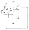
- the cooking appliance includes one Cooking space 140, which has a condenser drain line 141 with a condenser 121 connected.
- a drain line 123, a Overflow line 126 inside the capacitor 121 from a Siphon overflow system 128 is surrounded, a vent pipe 129 and one Condensation nozzle 142 connected.
- the siphon overflow system 128 is automatically shown over water from not shown Extinguishing nozzles filled to a water reservoir W for steam-tight sealing the overflow line 126 opposite the condenser 121.
- the water In normal operation, i.e. without blocking the drain line 123, the water drain off at a water level O via drain line 123.
- the water template W in the siphon overflow system 128 closes the overflow line 126 vapor-tight against the condenser 121 and emptied via the drain line 123 and not via the overflow line 126 on it due to the geometry of the Siphon overflow system 128 predetermined minimum. It is Siphon overflow system 128 dimensioned so that the water reservoir W itself in the event of brief pressure surges, such as when opening and closing the cooking appliance can occur, not emptied via the overflow line 126.
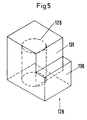
- the siphon overflow system 128 includes one adjacent the drain line 123 Shoulder 130 for retaining water reserve W in the siphon overflow system 128, and a partition 131 between the shoulder 130 and the overflow line 126, so that water between the shoulder 130 and the partition 131 in the Siphon overflow system 128 may rise in the event of a malfunction to a water level N to be able to drain via the overflow line 126.
- the maximum is Water level M, in the event of blockage of the drain line 123, with respect to the Water level N increased by the so-called overflow water level.
- the amount of Overflow water level is basically dependent on the amount of inflowing Water determined.
- FIG. 6 Another which works in principle like the embodiment just described An example of a siphon overflow system according to the invention in a cooking appliance is shown in 6, 7 and 8 are shown.
- the siphon overflow system 228 consists of a water tank with two legs 232, 233 for two interconnected water columns.
- One leg 232 is connected to an overflow pipe 226, while the second leg 233 projects into the condenser 221.
- the overflow line 226 is sealed in a steam-tight manner against the condenser 212.
- a water level N which is determined by the lower edge of the outlet opening in the leg 232, water can flow off via the overflow line 226, and the maximum water level M, in the event of a fault, within the condenser 221 is determined by the overflow edge of the outlet opening of the first leg 232.
Landscapes
- Health & Medical Sciences (AREA)
- Life Sciences & Earth Sciences (AREA)
- Engineering & Computer Science (AREA)
- Hydrology & Water Resources (AREA)
- Public Health (AREA)
- Water Supply & Treatment (AREA)
- Sink And Installation For Waste Water (AREA)
- Cookers (AREA)
- Commercial Cooking Devices (AREA)
- Jet Pumps And Other Pumps (AREA)
Claims (13)
- Appareil de cuisson avec un dispositif de sécurité incorporé à un système d'évacuation de l'eau de l'appareil de cuisson, où le système d'évacuation de l'eau comporte un récipient pour l'eau d'évacuation avec une conduite d'amenée et une conduite d'évacuation et où le dispositif de sécurité (128, 228) assure une étanchéité à la vapeur, grâce à un bouchon d'eau (W).
- Appareil de cuisson selon la revendication 1, caractérisé en ce que le système d'évacuation de l'eau comprend une conduite de débordement (126, 226) par laquelle une évacuation de l'eau ne peut s'effectuer qu'en cas de blocage de la conduite d'évacuation (123, 223) et en ce que la conduite de débordement (126, 226) est isolée d'une manière étanche à la vapeur du récipient pour l'eau d'évacuation (121, 221), grâce au bouchon d'eau (W).
- Appareil de cuisson selon la revendication 1 ou la revendication 2, caractérisé en ce que le bouchon d'eau (W) est complété au préalable avec de l'eau d'évacuation.
- Appareil de cuisson selon la revendication 1 ou la revendication 2, caractérisé en ce que le bouchon d'eau (W) est complété par un dispositif séparé d'alimentation en eau.
- Appareil de cuisson selon l'une des revendications précédentes, caractérisé en ce que le dispositif de sécurité (128, 228) est connecté avec la conduite d'évacuation (126, 226) de manière à évacuer l'eau du bouchon d'eau (W) lorsque son niveau dépasse une certaine limite supérieure dans le dispositif de sécurité (128, 228), par l'intermédiaire de la conduite d'évacuation (123, 223), pour autant que celle-ci ne soit pas bloquée.
- Appareil de cuisson selon l'une des revendications précédentes, caractérisé par un siphon pour vider le bouchon d'eau.
- Appareil de cuisson selon l'une des revendications 2 à 5, caractérisé en ce que le système d'évacuation par un siphon (128, 228) comprend le bouchon d'eau (W).
- Appareil de cuisson selon la revendication 7, caractérisé en ce que le système d'évacuation par un siphon (128) entoure la conduite de débordement (126), dont le côté supérieur avance dans le récipient pour l'eau d'évacuation (121) et dépasse le côté supérieur de la conduite d'évacuation (123), en ce qu'il comporte une ouverture pour l'eau en dessous du côté supérieur de la conduite de débordement (126) et audessus du côté supérieur de la conduite d'évacuation (123) pour que l'eau, lorsque la conduite d'évacuation (123) est bloquée, monte dans le système d'évacuation par un siphon (128) jusqu'au côté supérieur de la conduite de débordement (126) pour être évacuée par cette conduite.
- Appareil de cuisson selon la revendication 8, caractérisé en ce que le système d'évacuation par un siphon (128) comprend un épaulement 130 qui détermine la hauteur de l'ouverture pour l'eau et qui sert ainsi à retenir le bouchon d'eau (W) dans le système d'évacuation par un siphon (128) et une paroi de séparation (131) qui s'étend entre l'épaulement (130) et la conduite de débordement (126) pour permettre à l'eau de monter dans le système d'évacuation par un siphon (128).
- Appareil de cuisson selon la revendication 9, caractérisé en ce que l'ouverture pour l'eau du système d'évacuation par un siphon (128) se trouve entre l'épaulement (130) et la paroi de séparation (131), dont le côté inférieur se trouve sous le côté supérieur de l'épaulement (130).
- Appareil de cuisson selon la revendication 7, caractérisé en ce que le système d'évacuation par un siphon (228) a deux côtés (232, 233) solidaires l'un de l'autre, où un (232) des côtés constitue le côté d'évacuation de la conduite de débordement (226), ce côté d'évacuation déterminant le niveau maximum d'eau (M) possible dans le récipient pour l'eau d'évacuation (221) en cas de blocage de la conduite d'évacuation (223) et l'autre (233) des côtés s'étend à l'intérieur du récipient pour l'eau d'évacuation (221), le côté inférieur du récipient pour l'eau d'évacuation (221) ne dépassant toutefois pas le côté supérieur de la conduite de débordement (226).
- Appareil de cuisson selon l'une des revendications précédentes, caractérisé en ce que le récipient pour l'eau d'évacuation est réalisé sous la forme d'un condenseur (121, 221) entre une chambre de cuisson (140, 240) et le dispositif de sécurité (128, 228).
- Appareil de cuisson selon l'une des revendications précédentes, caractérisé en ce que le bouchon d'eau (W) peut être complété automatiquement avec de l'eau par une buse de remplissage.
Priority Applications (1)
| Application Number | Priority Date | Filing Date | Title |
|---|---|---|---|
| DE29724395U DE29724395U1 (de) | 1996-12-10 | 1997-10-06 | Gargerät mit Sicherungsvorrichtung für die Wasserversorgung |
Applications Claiming Priority (2)
| Application Number | Priority Date | Filing Date | Title |
|---|---|---|---|
| DE19651283A DE19651283C2 (de) | 1996-12-10 | 1996-12-10 | Sicherungssystem im Ablaufsystem eines Gargerätes |
| DE19651283 | 1996-12-10 |
Publications (3)
| Publication Number | Publication Date |
|---|---|
| EP0848115A2 EP0848115A2 (fr) | 1998-06-17 |
| EP0848115A3 EP0848115A3 (fr) | 1999-01-27 |
| EP0848115B1 true EP0848115B1 (fr) | 2001-12-12 |
Family
ID=7814227
Family Applications (1)
| Application Number | Title | Priority Date | Filing Date |
|---|---|---|---|
| EP97117235A Expired - Lifetime EP0848115B1 (fr) | 1996-12-10 | 1997-10-06 | Appareil de cuisine avec un dispositif de sécurité pour le réseau d'alimentation |
Country Status (3)
| Country | Link |
|---|---|
| EP (1) | EP0848115B1 (fr) |
| AT (1) | ATE210404T1 (fr) |
| DE (2) | DE19651283C2 (fr) |
Cited By (1)
| Publication number | Priority date | Publication date | Assignee | Title |
|---|---|---|---|---|
| DE102004001221A1 (de) * | 2004-01-07 | 2005-08-04 | Rational Ag | Vorrichtung und Verfahren zum Verschließen/Öffnen eines Behälters insbesondere eines Gargeräts |
Families Citing this family (7)
| Publication number | Priority date | Publication date | Assignee | Title |
|---|---|---|---|---|
| DE10038136B4 (de) * | 2000-08-04 | 2006-03-09 | BSH Bosch und Siemens Hausgeräte GmbH | Dampfgargerät |
| EP1314387A1 (fr) * | 2001-11-27 | 2003-05-28 | Bernhard Rzemieniuk | Appareil pour préparation d'aliments avec vapeur et/ou de l'air chaud |
| DE102004007236B4 (de) * | 2004-02-13 | 2007-05-10 | Convotherm Elektrogeräte GmbH | Dampferzeuger für gewerbliche Gargeräte, insbesondere Heißluftdämpfer |
| ES2287836T3 (es) | 2005-04-29 | 2007-12-16 | MKN MASCHINENFABRIK KURT NEUBAUER GMBH & CO. | Aparato de cocinado con una salida del recinto de cocinado y un sifon. |
| DE102006034081B4 (de) * | 2006-07-24 | 2015-03-05 | Rational Ag | Gargerät mit einer Ablaufvorrichtung |
| CN108331100A (zh) * | 2017-12-11 | 2018-07-27 | 江苏奥田环保设备有限公司 | 一种垃圾处理器污水排放装置 |
| CN109797810B (zh) * | 2019-01-17 | 2024-05-07 | 广东省水利水电科学研究院 | 一种应用于高水头供水构筑物的弯管分流消泡装置 |
Family Cites Families (7)
| Publication number | Priority date | Publication date | Assignee | Title |
|---|---|---|---|---|
| DE9202395U1 (de) * | 1992-02-25 | 1992-04-23 | Fiedler, Martin, 6411 Künzell | Behälter |
| EP0577548A1 (fr) * | 1992-06-30 | 1994-01-05 | Werner Nill | Siphon pour égouts |
| DE4225696A1 (de) * | 1992-08-04 | 1994-02-10 | Wiesheu Gmbh | Gerät für die Wärmebehandlung von Nahrungsmitteln |
| FR2711229B1 (fr) * | 1993-10-12 | 1995-12-08 | Bourgeois Ste Coop Prod | Four à vapeur muni d'un dispositif d'évacuation de la vapeur. |
| EP0750703B1 (fr) * | 1994-03-17 | 1997-12-03 | Triple Crown Securities Holdings Limited | Appareil de recyclage de l'eau |
| DE9416078U1 (de) * | 1994-10-06 | 1995-02-02 | Grübener, Werner, 57334 Bad Laasphe | Wasserversorgungsanlage |
| DE29518147U1 (de) * | 1995-11-16 | 1996-01-25 | Staudacher, Georg, 89358 Kammeltal | Vorrichtung zur Nutzung von Abwasser als Spülwasser |
-
1996
- 1996-12-10 DE DE19651283A patent/DE19651283C2/de not_active Expired - Fee Related
-
1997
- 1997-10-06 EP EP97117235A patent/EP0848115B1/fr not_active Expired - Lifetime
- 1997-10-06 DE DE59705762T patent/DE59705762D1/de not_active Expired - Fee Related
- 1997-10-06 AT AT97117235T patent/ATE210404T1/de not_active IP Right Cessation
Cited By (2)
| Publication number | Priority date | Publication date | Assignee | Title |
|---|---|---|---|---|
| DE102004001221A1 (de) * | 2004-01-07 | 2005-08-04 | Rational Ag | Vorrichtung und Verfahren zum Verschließen/Öffnen eines Behälters insbesondere eines Gargeräts |
| DE102004001221B4 (de) * | 2004-01-07 | 2009-02-12 | Rational Ag | Gargerät mit einer Vorrichtung zum Verschließen / Öffnen zumindest einer Öffnung und Verfahren hierzu |
Also Published As
| Publication number | Publication date |
|---|---|
| DE59705762D1 (de) | 2002-01-24 |
| EP0848115A3 (fr) | 1999-01-27 |
| DE19651283C2 (de) | 2003-03-27 |
| DE19651283A1 (de) | 2001-01-18 |
| ATE210404T1 (de) | 2001-12-15 |
| EP0848115A2 (fr) | 1998-06-17 |
Similar Documents
| Publication | Publication Date | Title |
|---|---|---|
| EP0219622B1 (fr) | Dispositif pour contrôler au moins un courant de gaz | |
| DE202017100626U1 (de) | System aus einem Geruchsverschluss und einem Aufnahmekörper sowie ein Geruchsverschluss | |
| EP0848115B1 (fr) | Appareil de cuisine avec un dispositif de sécurité pour le réseau d'alimentation | |
| DE69703630T2 (de) | Vorrichtung für die Beseitigung von Flüssigkeiten und/oder Verunreinigungen aus einem Gas | |
| DE4416462C2 (de) | Entlüftungsvorrichtung für eine Toilette | |
| DE69214775T2 (de) | Zwischenphase-Vakuumventil | |
| DE2838111C2 (fr) | ||
| DE19836563A1 (de) | Klarwasserabzug | |
| DE3822555C2 (fr) | ||
| DE69423160T2 (de) | Überdruckventil für einen Abfallbehälter | |
| EP0185109B1 (fr) | Siphon | |
| DE1935665C3 (de) | Sicherheits-Gaswaschflasche | |
| DE2714626C2 (de) | Vorrichtung zur Aufnahme und Ableitung von Abwasser aus tiefliegenden Räumen | |
| EP0565483B1 (fr) | Bassin dans une installation d'eaux usées | |
| DE19903952C2 (de) | Klosettbeckenentlüftung | |
| DE2340223C3 (de) | Kondenstopf | |
| DE2212112C3 (de) | Entlüftungsvorrichtung | |
| DE8206324U1 (de) | Vorrichtung zur automatischen Spülung von Absaug-Melkanlagen | |
| DE8620048U1 (de) | Naßbehandlungsgerät für fotografisches Material | |
| DE3934216A1 (de) | Einloch-mischbatterie mit ausziehbarer handbrause | |
| DE29702408U1 (de) | Zisterne mit Regenwasserfilter | |
| DE29724395U1 (de) | Gargerät mit Sicherungsvorrichtung für die Wasserversorgung | |
| EP0671966B1 (fr) | Dispositif d'extraction de liquides legers pour bac de separation | |
| EP0750073B1 (fr) | Chambre à eau d'un réservoir surélevé à eau potable | |
| DE2301976A1 (de) | Regenwasser-fallrohr u.dgl |
Legal Events
| Date | Code | Title | Description |
|---|---|---|---|
| PUAI | Public reference made under article 153(3) epc to a published international application that has entered the european phase |
Free format text: ORIGINAL CODE: 0009012 |
|
| AK | Designated contracting states |
Kind code of ref document: A2 Designated state(s): AT CH DE GB LI NL |
|
| AX | Request for extension of the european patent |
Free format text: AL;LT;LV;RO;SI |
|
| PUAL | Search report despatched |
Free format text: ORIGINAL CODE: 0009013 |
|
| AK | Designated contracting states |
Kind code of ref document: A3 Designated state(s): AT BE CH DE DK ES FI FR GB GR IE IT LI LU MC NL PT SE |
|
| AX | Request for extension of the european patent |
Free format text: AL;LT;LV;RO;SI |
|
| 17P | Request for examination filed |
Effective date: 19990709 |
|
| AKX | Designation fees paid |
Free format text: AT CH DE GB LI NL |
|
| RAP1 | Party data changed (applicant data changed or rights of an application transferred) |
Owner name: RATIONAL AG |
|
| 17Q | First examination report despatched |
Effective date: 20000809 |
|
| GRAG | Despatch of communication of intention to grant |
Free format text: ORIGINAL CODE: EPIDOS AGRA |
|
| RIC1 | Information provided on ipc code assigned before grant |
Free format text: 7A 47J 36/00 A |
|
| RTI1 | Title (correction) |
Free format text: COOKING APPLIANCE WITH A SECURITY DEVICE FOR THE WATER SUPPLY |
|
| GRAG | Despatch of communication of intention to grant |
Free format text: ORIGINAL CODE: EPIDOS AGRA |
|
| GRAH | Despatch of communication of intention to grant a patent |
Free format text: ORIGINAL CODE: EPIDOS IGRA |
|
| RIC1 | Information provided on ipc code assigned before grant |
Free format text: 7A 47J 36/00 A |
|
| RTI1 | Title (correction) |
Free format text: COOKING APPLIANCE WITH A SECURITY DEVICE FOR THE WATER SUPPLY |
|
| GRAH | Despatch of communication of intention to grant a patent |
Free format text: ORIGINAL CODE: EPIDOS IGRA |
|
| GRAA | (expected) grant |
Free format text: ORIGINAL CODE: 0009210 |
|
| AK | Designated contracting states |
Kind code of ref document: B1 Designated state(s): AT CH DE GB LI NL |
|
| REF | Corresponds to: |
Ref document number: 210404 Country of ref document: AT Date of ref document: 20011215 Kind code of ref document: T |
|
| REG | Reference to a national code |
Ref country code: CH Ref legal event code: NV Representative=s name: BUECHEL, KAMINSKI & PARTNER PATENTANWAELTE ESTABLI Ref country code: CH Ref legal event code: EP |
|
| REG | Reference to a national code |
Ref country code: GB Ref legal event code: IF02 |
|
| GBT | Gb: translation of ep patent filed (gb section 77(6)(a)/1977) |
Effective date: 20011212 |
|
| REF | Corresponds to: |
Ref document number: 59705762 Country of ref document: DE Date of ref document: 20020124 |
|
| PG25 | Lapsed in a contracting state [announced via postgrant information from national office to epo] |
Ref country code: AT Free format text: LAPSE BECAUSE OF NON-PAYMENT OF DUE FEES Effective date: 20021006 |
|
| PLBE | No opposition filed within time limit |
Free format text: ORIGINAL CODE: 0009261 |
|
| STAA | Information on the status of an ep patent application or granted ep patent |
Free format text: STATUS: NO OPPOSITION FILED WITHIN TIME LIMIT |
|
| 26N | No opposition filed | ||
| PG25 | Lapsed in a contracting state [announced via postgrant information from national office to epo] |
Ref country code: NL Free format text: LAPSE BECAUSE OF NON-PAYMENT OF DUE FEES Effective date: 20030501 |
|
| NLV4 | Nl: lapsed or anulled due to non-payment of the annual fee |
Effective date: 20030501 |
|
| PGFP | Annual fee paid to national office [announced via postgrant information from national office to epo] |
Ref country code: GB Payment date: 20031001 Year of fee payment: 7 |
|
| PGFP | Annual fee paid to national office [announced via postgrant information from national office to epo] |
Ref country code: CH Payment date: 20031017 Year of fee payment: 7 |
|
| PGFP | Annual fee paid to national office [announced via postgrant information from national office to epo] |
Ref country code: DE Payment date: 20031022 Year of fee payment: 7 |
|
| PG25 | Lapsed in a contracting state [announced via postgrant information from national office to epo] |
Ref country code: GB Free format text: LAPSE BECAUSE OF NON-PAYMENT OF DUE FEES Effective date: 20041006 |
|
| PG25 | Lapsed in a contracting state [announced via postgrant information from national office to epo] |
Ref country code: LI Free format text: LAPSE BECAUSE OF NON-PAYMENT OF DUE FEES Effective date: 20041031 Ref country code: CH Free format text: LAPSE BECAUSE OF NON-PAYMENT OF DUE FEES Effective date: 20041031 |
|
| PG25 | Lapsed in a contracting state [announced via postgrant information from national office to epo] |
Ref country code: DE Free format text: LAPSE BECAUSE OF NON-PAYMENT OF DUE FEES Effective date: 20050503 |
|
| GBPC | Gb: european patent ceased through non-payment of renewal fee |
Effective date: 20041006 |
|
| REG | Reference to a national code |
Ref country code: CH Ref legal event code: PL |