EP0848154A2 - Moteur à combustion contrÔlé par remplissage des cylindres avec un système d'admission d'air secondaire - Google Patents
Moteur à combustion contrÔlé par remplissage des cylindres avec un système d'admission d'air secondaire Download PDFInfo
- Publication number
- EP0848154A2 EP0848154A2 EP97120047A EP97120047A EP0848154A2 EP 0848154 A2 EP0848154 A2 EP 0848154A2 EP 97120047 A EP97120047 A EP 97120047A EP 97120047 A EP97120047 A EP 97120047A EP 0848154 A2 EP0848154 A2 EP 0848154A2
- Authority
- EP
- European Patent Office
- Prior art keywords
- combustion engine
- throttle
- internal combustion
- throttle valve
- air
- Prior art date
- Legal status (The legal status is an assumption and is not a legal conclusion. Google has not performed a legal analysis and makes no representation as to the accuracy of the status listed.)
- Withdrawn
Links
Images


Classifications
-
- F—MECHANICAL ENGINEERING; LIGHTING; HEATING; WEAPONS; BLASTING
- F02—COMBUSTION ENGINES; HOT-GAS OR COMBUSTION-PRODUCT ENGINE PLANTS
- F02M—SUPPLYING COMBUSTION ENGINES IN GENERAL WITH COMBUSTIBLE MIXTURES OR CONSTITUENTS THEREOF
- F02M35/00—Combustion-air cleaners, air intakes, intake silencers, or induction systems specially adapted for, or arranged on, internal-combustion engines
- F02M35/10—Air intakes; Induction systems
- F02M35/10242—Devices or means connected to or integrated into air intakes; Air intakes combined with other engine or vehicle parts
- F02M35/10255—Arrangements of valves; Multi-way valves
-
- F—MECHANICAL ENGINEERING; LIGHTING; HEATING; WEAPONS; BLASTING
- F02—COMBUSTION ENGINES; HOT-GAS OR COMBUSTION-PRODUCT ENGINE PLANTS
- F02D—CONTROLLING COMBUSTION ENGINES
- F02D9/00—Controlling engines by throttling air or fuel-and-air induction conduits or exhaust conduits
- F02D9/02—Controlling engines by throttling air or fuel-and-air induction conduits or exhaust conduits concerning induction conduits
-
- F—MECHANICAL ENGINEERING; LIGHTING; HEATING; WEAPONS; BLASTING
- F02—COMBUSTION ENGINES; HOT-GAS OR COMBUSTION-PRODUCT ENGINE PLANTS
- F02D—CONTROLLING COMBUSTION ENGINES
- F02D9/00—Controlling engines by throttling air or fuel-and-air induction conduits or exhaust conduits
- F02D9/08—Throttle valves specially adapted therefor; Arrangements of such valves in conduits
- F02D9/10—Throttle valves specially adapted therefor; Arrangements of such valves in conduits having pivotally-mounted flaps
- F02D9/1005—Details of the flap
- F02D9/101—Special flap shapes, ribs, bores or the like
- F02D9/1015—Details of the edge of the flap, e.g. for lowering flow noise or improving flow sealing in closed flap position
-
- F—MECHANICAL ENGINEERING; LIGHTING; HEATING; WEAPONS; BLASTING
- F02—COMBUSTION ENGINES; HOT-GAS OR COMBUSTION-PRODUCT ENGINE PLANTS
- F02D—CONTROLLING COMBUSTION ENGINES
- F02D9/00—Controlling engines by throttling air or fuel-and-air induction conduits or exhaust conduits
- F02D9/08—Throttle valves specially adapted therefor; Arrangements of such valves in conduits
- F02D9/10—Throttle valves specially adapted therefor; Arrangements of such valves in conduits having pivotally-mounted flaps
- F02D9/1035—Details of the valve housing
- F02D9/104—Shaping of the flow path in the vicinity of the flap, e.g. having inserts in the housing
-
- F—MECHANICAL ENGINEERING; LIGHTING; HEATING; WEAPONS; BLASTING
- F02—COMBUSTION ENGINES; HOT-GAS OR COMBUSTION-PRODUCT ENGINE PLANTS
- F02D—CONTROLLING COMBUSTION ENGINES
- F02D9/00—Controlling engines by throttling air or fuel-and-air induction conduits or exhaust conduits
- F02D9/08—Throttle valves specially adapted therefor; Arrangements of such valves in conduits
- F02D9/10—Throttle valves specially adapted therefor; Arrangements of such valves in conduits having pivotally-mounted flaps
- F02D9/1035—Details of the valve housing
- F02D9/1055—Details of the valve housing having a fluid by-pass
-
- F—MECHANICAL ENGINEERING; LIGHTING; HEATING; WEAPONS; BLASTING
- F02—COMBUSTION ENGINES; HOT-GAS OR COMBUSTION-PRODUCT ENGINE PLANTS
- F02D—CONTROLLING COMBUSTION ENGINES
- F02D9/00—Controlling engines by throttling air or fuel-and-air induction conduits or exhaust conduits
- F02D9/08—Throttle valves specially adapted therefor; Arrangements of such valves in conduits
- F02D9/10—Throttle valves specially adapted therefor; Arrangements of such valves in conduits having pivotally-mounted flaps
- F02D9/1065—Mechanical control linkage between an actuator and the flap, e.g. including levers, gears, springs, clutches, limit stops of the like
-
- F—MECHANICAL ENGINEERING; LIGHTING; HEATING; WEAPONS; BLASTING
- F02—COMBUSTION ENGINES; HOT-GAS OR COMBUSTION-PRODUCT ENGINE PLANTS
- F02M—SUPPLYING COMBUSTION ENGINES IN GENERAL WITH COMBUSTIBLE MIXTURES OR CONSTITUENTS THEREOF
- F02M3/00—Idling devices for carburettors
- F02M3/06—Increasing idling speed
-
- F—MECHANICAL ENGINEERING; LIGHTING; HEATING; WEAPONS; BLASTING
- F02—COMBUSTION ENGINES; HOT-GAS OR COMBUSTION-PRODUCT ENGINE PLANTS
- F02M—SUPPLYING COMBUSTION ENGINES IN GENERAL WITH COMBUSTIBLE MIXTURES OR CONSTITUENTS THEREOF
- F02M35/00—Combustion-air cleaners, air intakes, intake silencers, or induction systems specially adapted for, or arranged on, internal-combustion engines
- F02M35/10—Air intakes; Induction systems
- F02M35/104—Intake manifolds
- F02M35/108—Intake manifolds with primary and secondary intake passages
-
- F—MECHANICAL ENGINEERING; LIGHTING; HEATING; WEAPONS; BLASTING
- F02—COMBUSTION ENGINES; HOT-GAS OR COMBUSTION-PRODUCT ENGINE PLANTS
- F02D—CONTROLLING COMBUSTION ENGINES
- F02D9/00—Controlling engines by throttling air or fuel-and-air induction conduits or exhaust conduits
- F02D9/02—Controlling engines by throttling air or fuel-and-air induction conduits or exhaust conduits concerning induction conduits
- F02D2009/0201—Arrangements; Control features; Details thereof
- F02D2009/0279—Throttle valve control for intake system with two parallel air flow paths, each controlled by a throttle, e.g. a resilient flap disposed on a throttle
Definitions
- the invention relates to a quantity-controlled internal combustion engine with at least a throttle device provided in the intake tract and with a System for introducing additional air into the intake ducts of the individual Internal combustion engine cylinder, with a control element for influencing the Additional air volume is provided.
- the technical environment is based on the DE 40 41 628 A1 referenced.
- the mixture can be prepared in this way in front of and in the cylinder can be significantly improved.
- the Additional air can be introduced via so-called air-coated fuel injection valves take place, as shown in DE 40 41 628 A1. It it is also possible, the additional air via a separate, for example nozzle-like initiate trained inlet opening in each cylinder intake port. This can also be used to increase the charge movement and Improvement of the combustion properties through targeted introduction an additional amount of air in the inlet channel or in the combustion chamber good conditions be created for an improved combustion process. This results in cheaper fuel consumption and higher residual gas compatibility and thus lower exhaust emissions, as well as an improved Smooth running of the internal combustion engine.
- a separate control element can be provided which supplies the additional air system with an intake air flow or prevents the introduction of intake air into the additional air system.
- this control element is designed as a separate air shut-off valve, which, however, can only release or shut off the additional air system.
- the amount of intake air actually entering the auxiliary air system is determined via the delivery rate of a separate air pump.
- this is relatively complex since not only a large number of components but also separate control logic is required.
- auxiliary air system which introduces an auxiliary air flow into the intake ducts of the individual internal combustion engine cylinders, directly from the intake tract of the internal combustion engine, but it is also necessary here to control the amount of auxiliary air flow provide separate control body.
- the above separate control body is extreme in terms of its operation easy to design if the actuation of the control element is practically together with the actuation of the throttle body.
- This coupling is preferred the actuation so designed that starting from a closed position both the control element and the throttle element in the event of a load increase initially only the control unit opens and thereby the system to supply additional air with intake air while the throttle body the intake tract for supplying the intake ducts with intake air only releases with a further increase in load.
- This allows the so-called additional air system in its main operating area, namely the low load area the internal combustion engine, which have the greatest possible effect.
- the control element arrives after a certain opening path of the throttle body back into its Closed position. This is the function of the control body for supply the so-called. Additional air system designed such that this system no additional air into the intake ducts of the individual internal combustion engine cylinders is initiated when or after the throttle body one has reached a certain degree of opening and the intake air flow of the internal combustion engine at a higher part-load operating point or full-load operating point the same essentially via the throttle body in the Internal combustion engine suction system arrives. This is because in these mentioned operating points ideal inflow conditions of the intake air into the intake ducts.
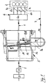
- the intake tract of a quantity-controlled, multi-cylinder Internal combustion engine 2 designated.
- Components of the intake tract 1 are, as usual, an intake air filter 3, an air mass meter 4, a Quantity control throttle body 5, and a suction system 6, these individual elements of course through air lines are interconnected. Partly the direction of flow of the intake air represented by arrows.
- the suction system 6 has a collecting volume 6a and several Intake ducts 6b leading from the collecting volume 6a to the individual cylinders the internal combustion engine 2 lead.
- Part of the intake tract 1 is a so-called.
- Additional air system 7, via which in the individual intake ducts 6b of the intake system 6 additional air flows can be initiated by the intake air flow of the internal combustion engine 2 are branched off. This can be done at any point in the Intake tract 1, however, preferably downstream of the air mass meter 4 So-called air branch 7a can be provided, from which an air line 7b into the Proximity of the suction system 6, where it leads into individual inlet nozzles 7c, from each of which opens into an intake duct 6b, branches.
- suitable bores or Slits may be provided in the intake ducts 6b.
- this auxiliary air system 7 is used for improvement the mixture preparation in the intake channels 6b, in which of course additionally open fuel injection valves, not shown (can).
- a control element 8 is also provided, with the aid of the control element 8 that supplied to the auxiliary air system 7 or that of the internal combustion engine 2
- the additional air quantity supplied via the additional air system 7 can be changed.
- control member 8 is in the Throttle body 5 integrated, as will be explained in more detail below.
- the throttle body 5 as one in a throttle body 5a an axis of rotation 5b pivotable throttle valve 5c - and thus as in Internal combustion engines usual - trained.
- the throttle valve 5c is pivoted slightly in the direction of the arrow 9 and consequently performs a slight opening movement, the air branch 7a is released, so that at least some of the intake air brought in by the air mass meter 4 into the additional air System 7 and can get more precisely into the air line 7b of the same.
- the flow path for the intake air through the throttle valve connector 5a directly into the collection volume 6a of the intake system 6 is still largely blocked, also due to the spherical shape of the inner wall of the throttle valve connector 5a in the area of the throttle valve 5c.
- this inner wall section of the throttle valve connector 5a in the region of the throttle valve 5c is preferably designed as a spherical zone.
- control element in the embodiment of FIG. 1 just explained 8 is arranged as an attachment 8 'on the throttle valve 5c itself each time the throttle valve 5c is actuated Actuation of the control element 8, in the desired manner. It is namely desired that the control member when the throttle valve 5c is closed 8 is closed, so that no intake air flow in the auxiliary air system 7 can reach. If the throttle valve opens slightly 5c, however, should initially only include the auxiliary air system 7 Intake air are supplied while a further opening movement takes place the throttle valve 5c also the complete intake system 6, d. H. the collection volume 6a of the same is to be supplied with intake air.
- control element 8 shown, after its actuation mechanically to the actuation of the throttle element 5 or the throttle valve 5c is coupled. It is therefore not necessary for the control element 8, with the help of which the intake air supply of the Additional air system 7 is controlled to provide a separate actuation.
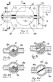
- FIG. 2 A preferred such system with a register throttle body 10 is shown in Figure 2 and in the other figures 3 to 6d further trained.
- the control element 8 is - as in FIG. 2 shows - downstream of the air branch 7a in the air line 7b of the additional air system 7 provided.
- the control body provides 8, so to speak, the first stage of the register throttle valve connector 10 represents, while the trained as a conventional throttle valve 5c and in a duct piece 10b, which is part of the throttle valve connector 10 is arranged throttle body 5 forms the second stage.
- the throttle valve 5c and the control member 8 which is designed as a roller segment slide 8a and is arranged in a channel piece 10a of the register throttle valve connector 10, which is part of the air line 7b, are located on a common rotary shaft 11 By rotating this rotary shaft 11 about its axis of rotation, both the throttle valve 5c and the control element 8 or the roller segment slide 8a can thus be pivoted in or against the direction of the arrow 9.
- Figures 2, 3 clearly show the structure of the register throttle valve connector 10, which contains both the throttle element 5 in an associated channel piece 10b and (adjacent) the control element 8 in the associated channel piece 10a.
- the guidance of the section CC in FIG. 3 makes it clear that in the illustration in FIG. 2 the duct section 10b is located behind the duct section 10a. Accordingly, the lower half of the throttle valve 5c is shown in dashed lines in FIG. 2.
- the throttle element 5 or the throttle valve 5c is first in FIG a closed position shown in FIG. 2.
- the control element 8 or the roller segment slide 8a deviates from at idle operating point the representation in Fig. 2 an intermediate position between fully open (this is shown in Fig.2) and completely closed (this is in the figures 6a, 6b). This leads on the one hand and the good meterability due to the cheaper mixture preparation on the other hand to an improved Idle quality.
- the load is increased from the idling operating point Internal combustion engine initiated, it is based on the still closed Position of the throttle element 5 by rotating the rotary shaft 11 in addition to the control element 8 or the roller segment slide 8a also the throttle valve 5c is pivoted according to the direction of arrow 9.
- the Control member 8 By the Control member 8, the free cross section of the duct piece 10a is increased and finally assumes the position shown in Fig. 2. This can be based on by far the largest part of the air branch 7a from the air mass meter 4 introduced intake air into the auxiliary air system 7 get more precisely via the air line 7b thereof to the nozzles 7c.
- the throttle valve 5c is moved further in the direction of an opening movement (arrow direction 9), after which the throttling function of the throttle valve 5c is reduced to such an extent that the majority of the intake air flow directly through the duct section 10b into the intake system 6 that is, in the collection volume 6a thereof. Then the internal combustion engine is operated at a higher part-load operating point or under full load. Since in these operating points no additional air is to get into the intake ducts 6b via the additional air system 7, this further opening movement of the throttle valve 5c according to arrow direction 9 goes hand in hand with a closing movement of the control element 8.
- the roller segment slide 8a After a certain opening path of the throttle element 5, the roller segment slide 8a, which is also pivoted further in the direction of the arrow 9, reaches a position closing the channel piece 10a, the left half of the roller segment slide 8a in FIG. 2 now blocking the channel piece 10a, whereas in the starting position explained above, 6a, 6b this shut-off was carried out with the right half of the roller segment slide 8a.
- the control element 8 is also actuated in the desired manner.
- the control member 8 is also closed when the throttle valve 5c is closed, so that no intake air flow can get into the additional air system 7.
- the additional air system 7 is to be supplied with intake air, while only when the throttle valve 5c opens further does the complete intake system 6, ie the collection volume 6a thereof, are to be supplied with intake air.
- This is also possible in a simple manner with this control element 8 after its actuation is mechanically coupled to the actuation of the throttle element 5 (the throttle valve 5c).
- control element 8 is to assume its closed position again, which is also ensured in a simple manner due to the design described. It is therefore not necessary to provide a separate actuation for the control element 8, with the aid of which the intake air supply of the additional air system 7 is controlled.
- FIGS. 6a to 6d Possible structural embodiments for the control element 8 according to the exemplary embodiment according to FIGS. 2, 3 are shown in FIGS. 6a to 6d.
- the sectional representations in each case through the channel piece 10a show different shapes for the control element 8. Analogously to FIG. 2, this is formed in FIGS. 6a, 6b as a roller segment slide 8a, the segment of the corresponding roller extending over different angular ranges. As a result, it can thus be determined at what angle of rotation of the rotary shaft 11 the additional air system 7 is opened or closed.
- FIG. 6a, 6d Possible structural embodiments for the control element 8 according to the exemplary embodiment according to FIGS. 2, 3 are shown in FIGS. 6a to 6d.
- the sectional representations in each case through the channel piece 10a show different shapes for the control element 8. Analogously to FIG. 2, this is formed in FIGS. 6a, 6b as a roller segment slide 8a, the segment of the corresponding roller extending over different angular ranges.
- the control element 8 is designed as a roller rotary valve 8b with a central passage 8c which, depending on the angular position of the roller rotary valve 8b, can coincide with the duct piece 10a and thus releases the auxiliary air system 7, or else blocks it when the central passage 8c lies outside the duct section 10a.
- the control element 8 being designed as a rotary flap 8d, which is arranged in a correspondingly enlarged section 10a 'of the channel piece 10a such that, as can be seen, the right and left sides of the rotary flap 8d are offset from one another in the enlarged section 10a 'opening channel pieces 10a are either connected to each other or interrupted by the rotary flap 8d.
- FIGS. 4 and 5 A further exemplary embodiment of a register throttle valve connector 10 with a throttle element 5 and a control element 8, which can be actuated together in the desired manner, is shown in FIGS. 4 and 5.
- the control element 8 which is designed analogously to FIGS. 6a-6d and is arranged in a channel piece 10a in the register throttle valve connector 10, has its own rotary shaft 11a, which is initially independently rotatable by the rotary shaft 11b of the throttle valve 5c or the throttle element 5.
- the two rotary shafts 11a and 11b are arranged coaxially to one another, ie the rotary shaft 11a carrying the control element 8 runs within the hollow rotary shaft 11b which actuates the throttle element 5.
- the rotary shaft 11a or the rotary shaft 11 is actuated by an electric servomotor 14, the pinion 14a of which meshes with a toothed-disk segment 15 seated on the rotary shaft 11 / 11a.
- an electric servomotor 14 the pinion 14a of which meshes with a toothed-disk segment 15 seated on the rotary shaft 11 / 11a.
- the two rotary shafts 11a, 11b are additionally functionally connected to one another via an entrainment device 13 that enables an initial freewheeling, such that - starting from the closed position of the throttle element 5 and the control element 8 - in one by a servomotor 14 initiated rotational movement of the control element rotary shaft 11a, the rotary shaft 11b of the throttle element 5 initially does not move and is only taken along by the rotary shaft 11a after a certain opening movement of the control element in the sense of a rotational movement now also opening the throttle element 5.
- a drive plate 13b which is connected in a rotationally fixed manner to the rotary shaft 11b and which has a slot 13c which extends over a certain angular segment and into which a drive pin 13a which is connected to the toothed disk segment 15 of the rotary shaft 11a engages.
- the slot 13c in the drive plate 13b enables the initial freewheeling;
- the driving pin 13a comes to a stop on the driving plate 13b at the other end of the slot 13c, the rotary shaft 11b and thus the throttle element 5 are taken along in the sense of an opening movement when the driving pin 13a is rotated or swiveled in the direction of the arrow 9.
Landscapes
- Engineering & Computer Science (AREA)
- Chemical & Material Sciences (AREA)
- Combustion & Propulsion (AREA)
- Mechanical Engineering (AREA)
- General Engineering & Computer Science (AREA)
- Control Of Throttle Valves Provided In The Intake System Or In The Exhaust System (AREA)
Applications Claiming Priority (4)
| Application Number | Priority Date | Filing Date | Title |
|---|---|---|---|
| DE19651647 | 1996-12-12 | ||
| DE19651647A DE19651647A1 (de) | 1996-12-12 | 1996-12-12 | Quantitätsgesteuerte Brennkraftmaschine mit einem System zur Einleitung von Zusatzluft |
| DE19701757 | 1997-01-20 | ||
| DE19701757A DE19701757A1 (de) | 1996-12-12 | 1997-01-20 | Quantitätsgesteuerte Brennkraftmaschine mit einem System zur Einleitung von Zusatzluft |
Publications (2)
| Publication Number | Publication Date |
|---|---|
| EP0848154A2 true EP0848154A2 (fr) | 1998-06-17 |
| EP0848154A3 EP0848154A3 (fr) | 1999-03-31 |
Family
ID=26032133
Family Applications (1)
| Application Number | Title | Priority Date | Filing Date |
|---|---|---|---|
| EP97120047A Withdrawn EP0848154A3 (fr) | 1996-12-12 | 1997-11-15 | Moteur à combustion contrÔlé par remplissage des cylindres avec un système d'admission d'air secondaire |
Country Status (2)
| Country | Link |
|---|---|
| EP (1) | EP0848154A3 (fr) |
| DE (1) | DE19701757A1 (fr) |
Cited By (3)
| Publication number | Priority date | Publication date | Assignee | Title |
|---|---|---|---|---|
| WO2002025085A1 (fr) * | 2000-09-25 | 2002-03-28 | Internova International Innovation Company B.V. | Dispositif d'admission d'air pour un moteur thermique |
| WO2009130028A1 (fr) * | 2008-04-25 | 2009-10-29 | Friedrich Boysen Gmbh & Co. Kg | Soupape à volet |
| EP3620698A1 (fr) * | 2018-09-06 | 2020-03-11 | United Technologies Corporation | Vanne papillon globulaire |
Citations (2)
| Publication number | Priority date | Publication date | Assignee | Title |
|---|---|---|---|---|
| DE3239577A1 (de) | 1981-10-27 | 1983-05-11 | Suzuki Jidosha Kogyo K.K., Kami, Shizuoka | Drosselsteuervorrichtung fuer eine brennkraftmaschine |
| DE4041628A1 (de) | 1990-12-22 | 1992-07-02 | Daimler Benz Ag | Gemischverdichtende brennkraftmaschine mit sekundaerlufteinblasung und mit luftmassenmessung im saugrohr |
Family Cites Families (16)
| Publication number | Priority date | Publication date | Assignee | Title |
|---|---|---|---|---|
| DE677078C (de) * | 1935-07-26 | 1939-06-17 | Thomas James Swinney | Mischvorrichtung fuer Brennkraftmaschinen |
| JPS511841A (fr) * | 1974-06-21 | 1976-01-09 | Hitachi Ltd | |
| JPS54163212A (en) * | 1978-06-15 | 1979-12-25 | Toyota Motor Co Ltd | Suction device for internal combustion engine |
| JPS5841255A (ja) * | 1981-09-07 | 1983-03-10 | Suzuki Motor Co Ltd | 内燃機関の吸気装置 |
| DE3217251A1 (de) * | 1982-05-07 | 1983-11-10 | Bayerische Motoren Werke AG, 8000 München | Ansaugsystem fuer gemischverdichtende, fremdgezuendete mehrzylinder-brennkraftmaschinen |
| FR2573485A1 (fr) * | 1984-11-20 | 1986-05-23 | Pierburg Gmbh & Co Kg | Dispositif de formation du melange pour des moteurs a combustion interne a plusieurs cylindres |
| DE3641273C2 (de) * | 1985-12-12 | 1994-12-08 | Volkswagen Ag | Saugrohranordnung für eine Dieselmaschine |
| JPH0663471B2 (ja) * | 1986-02-13 | 1994-08-22 | 本田技研工業株式会社 | 内燃機関の補助空気量制御装置 |
| DE3905655C2 (de) * | 1989-02-24 | 2000-10-12 | Bosch Gmbh Robert | Steuervorrichtung |
| JPH03156140A (ja) * | 1989-08-20 | 1991-07-04 | Nippondenso Co Ltd | エンジンのアイドリング制御弁 |
| DE4037913A1 (de) * | 1990-08-28 | 1992-06-04 | Bayerische Motoren Werke Ag | Steuerverfahren fuer ein abgasrueckfuehr-steuerorgan |
| DE4202406C1 (en) * | 1992-01-29 | 1993-03-18 | Mercedes-Benz Aktiengesellschaft, 7000 Stuttgart, De | IC engine air intake control with two intake ducts - has each duct with throttle flap, one for medium and top load, and second for idling |
| JPH06213107A (ja) * | 1992-09-09 | 1994-08-02 | Nippondenso Co Ltd | 内燃機関の吸気絞り弁装置 |
| DE4239069C2 (de) * | 1992-11-20 | 1999-02-18 | Fredi Alexander Pommer | Vorrichtung zur Zuführung von Zusatzluft in den Ansaugkanal einer Brennkraftmaschine |
| KR100329166B1 (ko) * | 1993-07-09 | 2002-08-28 | 가부시끼가이샤 히다치 세이사꾸쇼 | 내연기관의제어장치및와류발생장치 |
| GB9426399D0 (en) * | 1994-12-30 | 1995-03-01 | Ford Motor Co | Engine management system |
-
1997
- 1997-01-20 DE DE19701757A patent/DE19701757A1/de not_active Withdrawn
- 1997-11-15 EP EP97120047A patent/EP0848154A3/fr not_active Withdrawn
Patent Citations (2)
| Publication number | Priority date | Publication date | Assignee | Title |
|---|---|---|---|---|
| DE3239577A1 (de) | 1981-10-27 | 1983-05-11 | Suzuki Jidosha Kogyo K.K., Kami, Shizuoka | Drosselsteuervorrichtung fuer eine brennkraftmaschine |
| DE4041628A1 (de) | 1990-12-22 | 1992-07-02 | Daimler Benz Ag | Gemischverdichtende brennkraftmaschine mit sekundaerlufteinblasung und mit luftmassenmessung im saugrohr |
Cited By (6)
| Publication number | Priority date | Publication date | Assignee | Title |
|---|---|---|---|---|
| WO2002025085A1 (fr) * | 2000-09-25 | 2002-03-28 | Internova International Innovation Company B.V. | Dispositif d'admission d'air pour un moteur thermique |
| FR2814501A1 (fr) * | 2000-09-25 | 2002-03-29 | Internova Int Innovation | Dispositif d'admission d'air pour un moteur thermique |
| WO2009130028A1 (fr) * | 2008-04-25 | 2009-10-29 | Friedrich Boysen Gmbh & Co. Kg | Soupape à volet |
| EP3620698A1 (fr) * | 2018-09-06 | 2020-03-11 | United Technologies Corporation | Vanne papillon globulaire |
| US20200080658A1 (en) * | 2018-09-06 | 2020-03-12 | United Technologies Corporation | Globe butterfly valve |
| US10823302B2 (en) * | 2018-09-06 | 2020-11-03 | Raytheon Technologies Corporation | Globe butterfly valve |
Also Published As
| Publication number | Publication date |
|---|---|
| EP0848154A3 (fr) | 1999-03-31 |
| DE19701757A1 (de) | 1998-08-20 |
Similar Documents
| Publication | Publication Date | Title |
|---|---|---|
| DE2803533A1 (de) | Luftverdichtende, selbstzuendende brennkraftmaschine | |
| AT402326B (de) | Zylinderkopf für eine brennkraftmaschine | |
| DE3446377A1 (de) | Ansaugvorrichtung fuer kolben-verbrennungskraftmaschinen | |
| DE3909837A1 (de) | Saugrohranlage fuer eine mehrzylinder-brennkraftmaschine | |
| DE102008048912B4 (de) | Abgasanlage und Abgasventil zur Steuerung eines Volumenstroms von Abgas sowie ein Verfahren zur Steuerung eines Volumenstroms | |
| DE4039992C2 (fr) | ||
| DE69000139T2 (de) | Einlassvorrichtung fuer brennkraftmaschine. | |
| EP0848154A2 (fr) | Moteur à combustion contrÔlé par remplissage des cylindres avec un système d'admission d'air secondaire | |
| EP0954686B1 (fr) | Tubulure d'aspiration pour la regulation de la consommation d'air dans le systeme d'aspiration d'un moteur a combustion interne | |
| DE2507413A1 (de) | Vergaser mit verstellbarem lufttrichter | |
| DE2928590A1 (de) | Frischluftleitung fuer hubkolbenbrennkraftmaschinen mit einlassdrallkanaelen | |
| WO2006111280A1 (fr) | Moteur thermique a recyclage des gaz d'echappement | |
| DE2557533C3 (de) | Gemischansaugende Kreiskolben-Brennkraftmaschine | |
| DE29507321U1 (de) | Kolbenbrennkraftmaschine mit zumindest zwei Einlaßventilen je Zylinder | |
| EP1025349A2 (fr) | Tambour d'ouverture ou de fermeture | |
| DE19651647A1 (de) | Quantitätsgesteuerte Brennkraftmaschine mit einem System zur Einleitung von Zusatzluft | |
| DE377554C (de) | Vergaser mit in einem von dem Hauptluftrohr abgezweigten Luftkanal liegender Brennstoffduese | |
| EP0822325A2 (fr) | Dispositif de commande de la section d'aspiration de conduits d'admission d'air de moteurs à combustion | |
| DE19516926A1 (de) | Drosselklappe | |
| DE3339680C1 (de) | Vorrichtung für Gemischbildung für Brennkraftmaschinen | |
| DE102005059080A1 (de) | Vergaser für einen Verbrennungsmotor sowie Verfahren zur gesteuerten Kraftstoffzufuhr | |
| DE832362C (de) | Hilfsstartvergaser zur Inbetriebsetzung und fuer den Betrieb von Verbrennungsmotorenin kaltem Zustand | |
| DE2945824A1 (de) | Einstellbarer venturi-vergaser | |
| DE19754139A1 (de) | Ansaugluftverteiler einer mehrzylindrigen Brennkraftmaschine, insbesondere für ein Zusatz-Ansaugluftsystem | |
| DE102018210078B4 (de) | Ventileinheit und Verwendung einer derartigen Ventileinheit |
Legal Events
| Date | Code | Title | Description |
|---|---|---|---|
| PUAI | Public reference made under article 153(3) epc to a published international application that has entered the european phase |
Free format text: ORIGINAL CODE: 0009012 |
|
| AK | Designated contracting states |
Kind code of ref document: A2 Designated state(s): AT BE CH DE DK ES FI FR GB GR IE IT LI LU MC NL PT SE |
|
| AX | Request for extension of the european patent |
Free format text: AL;LT;LV;MK;RO;SI |
|
| PUAL | Search report despatched |
Free format text: ORIGINAL CODE: 0009013 |
|
| AK | Designated contracting states |
Kind code of ref document: A3 Designated state(s): AT BE CH DE DK ES FI FR GB GR IE IT LI LU MC NL PT SE |
|
| AX | Request for extension of the european patent |
Free format text: AL;LT;LV;MK;RO;SI |
|
| AKX | Designation fees paid | ||
| STAA | Information on the status of an ep patent application or granted ep patent |
Free format text: STATUS: THE APPLICATION IS DEEMED TO BE WITHDRAWN |
|
| 18D | Application deemed to be withdrawn |
Effective date: 19991001 |
|
| REG | Reference to a national code |
Ref country code: DE Ref legal event code: 8566 |