EP0848183A2 - Support hydraulique à chambres multiples - Google Patents
Support hydraulique à chambres multiples Download PDFInfo
- Publication number
- EP0848183A2 EP0848183A2 EP97120904A EP97120904A EP0848183A2 EP 0848183 A2 EP0848183 A2 EP 0848183A2 EP 97120904 A EP97120904 A EP 97120904A EP 97120904 A EP97120904 A EP 97120904A EP 0848183 A2 EP0848183 A2 EP 0848183A2
- Authority
- EP
- European Patent Office
- Prior art keywords
- chamber
- membrane
- throttle
- compensation chamber
- hydraulic
- Prior art date
- Legal status (The legal status is an assumption and is not a legal conclusion. Google has not performed a legal analysis and makes no representation as to the accuracy of the status listed.)
- Granted
Links
- 239000012528 membrane Substances 0.000 claims abstract description 28
- 239000012530 fluid Substances 0.000 claims abstract description 3
- 238000005192 partition Methods 0.000 claims description 6
- 239000013536 elastomeric material Substances 0.000 claims description 2
- 229920001971 elastomer Polymers 0.000 abstract 1
- 239000000806 elastomer Substances 0.000 abstract 1
- 239000000463 material Substances 0.000 abstract 1
- 238000013016 damping Methods 0.000 description 8
- 238000010276 construction Methods 0.000 description 6
- 230000000694 effects Effects 0.000 description 4
- 239000006096 absorbing agent Substances 0.000 description 2
- 238000013459 approach Methods 0.000 description 1
- 230000005540 biological transmission Effects 0.000 description 1
- 230000005284 excitation Effects 0.000 description 1
- 238000009413 insulation Methods 0.000 description 1
- 239000007788 liquid Substances 0.000 description 1
- 238000004519 manufacturing process Methods 0.000 description 1
- 230000008439 repair process Effects 0.000 description 1
- 238000007789 sealing Methods 0.000 description 1
- 230000035939 shock Effects 0.000 description 1
- 239000000725 suspension Substances 0.000 description 1
Images

Classifications
-
- F—MECHANICAL ENGINEERING; LIGHTING; HEATING; WEAPONS; BLASTING
- F16—ENGINEERING ELEMENTS AND UNITS; GENERAL MEASURES FOR PRODUCING AND MAINTAINING EFFECTIVE FUNCTIONING OF MACHINES OR INSTALLATIONS; THERMAL INSULATION IN GENERAL
- F16F—SPRINGS; SHOCK-ABSORBERS; MEANS FOR DAMPING VIBRATION
- F16F13/00—Units comprising springs of the non-fluid type as well as vibration-dampers, shock-absorbers, or fluid springs
- F16F13/04—Units comprising springs of the non-fluid type as well as vibration-dampers, shock-absorbers, or fluid springs comprising both a plastics spring and a damper, e.g. a friction damper
- F16F13/06—Units comprising springs of the non-fluid type as well as vibration-dampers, shock-absorbers, or fluid springs comprising both a plastics spring and a damper, e.g. a friction damper the damper being a fluid damper, e.g. the plastics spring not forming a part of the wall of the fluid chamber of the damper
- F16F13/08—Units comprising springs of the non-fluid type as well as vibration-dampers, shock-absorbers, or fluid springs comprising both a plastics spring and a damper, e.g. a friction damper the damper being a fluid damper, e.g. the plastics spring not forming a part of the wall of the fluid chamber of the damper the plastics spring forming at least a part of the wall of the fluid chamber of the damper
- F16F13/10—Units comprising springs of the non-fluid type as well as vibration-dampers, shock-absorbers, or fluid springs comprising both a plastics spring and a damper, e.g. a friction damper the damper being a fluid damper, e.g. the plastics spring not forming a part of the wall of the fluid chamber of the damper the plastics spring forming at least a part of the wall of the fluid chamber of the damper the wall being at least in part formed by a flexible membrane or the like
- F16F13/105—Units comprising springs of the non-fluid type as well as vibration-dampers, shock-absorbers, or fluid springs comprising both a plastics spring and a damper, e.g. a friction damper the damper being a fluid damper, e.g. the plastics spring not forming a part of the wall of the fluid chamber of the damper the plastics spring forming at least a part of the wall of the fluid chamber of the damper the wall being at least in part formed by a flexible membrane or the like characterised by features of partitions between two working chambers
- F16F13/107—Passage design between working chambers
Definitions
- the invention relates to a multi-chamber hydraulic bearing for elastic support of aggregates, especially of Motor vehicle engines, with one with hydraulic fluid filled hydraulic chamber, which by a with a Throttle opening provided partition in two rooms, one Working chamber and a compensation chamber, is divided, the compensation chamber with a compensation chamber membrane is completed, according to the preamble of Claim 1.
- the elasticity of the hydraulic bearing forms in Interact with the mass of the engine to be supported vibrating structure. Below the natural frequency chassis and the supported motor move more or less in conflict with each other.
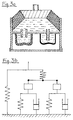
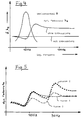
- Hydraulically damped engine mounts are usually designed in such a way that they greatly reduce the resonance vibrations of the engine in the vertical direction (usually in the frequency range 6 - 12 Hz) due to a pronounced damping maximum and a damper effect (Fig. 4).
- the design results in an increase in the dynamic spring rate to a second stiffness level. This always applies to larger amplitudes. For smaller amplitudes, decoupling in the damping device can ensure that the original stiffness level is maintained up to high frequencies.
- the hydraulic bearing presented here is based on the latter principle.
- the object of the invention consists in creating a simplified, inexpensive Construction.
- the hydraulic bearing according to the invention is characterized in that the second damping maximum can be implemented in existing hydraulic bearing constructions with little or no additional cost.
- the construction according to the invention advantageously combines the properties given with a free path with the second damping maximum given with a further compensation chamber. This means: good insulation is guaranteed at low amplitudes and high frequencies.
- the multi-chamber hydraulic bearing according to the invention is easy to manufacture. Compared to known single-chamber hydraulic bearings, only a few additional components are required. Therefore, the bearing can be manufactured inexpensively. The structure is compact and robust and therefore less prone to failure and repairs.
- the construction according to the invention is based on a universal basic bearing concept. This enables variants with one and two compensation chambers. For this purpose, the conventional membrane is exchanged for the membrane according to the invention with a second compensation chamber in existing series bearings. A complex new construction and new tools are not necessary.
- the throttle diaphragm is in the ring-shaped Throttle disc incorporated.
- a free path results from the fact that the second compensation chamber membrane on the Throttle diaphragm is attached. When attached to the Partition would not be completely decoupled.
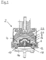
- the multi-chamber hydraulic bearing according to the invention shown in Fig. 1 2 consists essentially of a with Liquid-filled hydraulic chamber 4 through a Throttle disc (partition) 6 in a working chamber 8 and a (first) compensation chamber 10 is divided.
- Throttle disc 6 is an annular channel 12 as a (first) Flow connection between working chamber 8 and (first) Compensation chamber 10 is provided.
- the compensation chamber 10 is on its side facing away from the throttle disc 6 with a (First) compensation chamber membrane 14 completed.
- a throttle diaphragm (Decoupling membrane) 16 inserted, preferably with a free path can be moved back and forth.
- the throttle diaphragm 16 has at least one parallel to the free path switched additional according to the invention
- Flow connection 18 that leads to a further (second) Compensation chamber 20 leads in such a way that the first Compensation chamber 10 with the other (second) Compensation chamber 20 via this additional flow channel 18 communicates.
- the second compensation chamber 20 is hydraulically separated from the working chamber 8 by means of a second compensation chamber membrane 22.
- the throttle diaphragm 16 and the second compensation chamber diaphragm 22 are preferably made of elastomeric material and are formed in one piece as a unit.
- the dent resistance of the (second) Compensation chamber membrane 22 must be significantly above that (First) compensation chamber membrane 10 of the hydraulic bearing 2 so that the first damping maximum does not increase greatly reduced.
- the channel 18 in the throttle membrane (decoupling membrane) 16 can be straight or formed as a circumferential ring channel be.
- the compensation chamber 20 for the second channel 18 can itself in the compensation chamber 10 of the hydraulic bearing 2, however are also in the working chamber 8.
- the Decoupling membrane 16 with a second channel 18 can be like that conventional for acoustic decoupling with a Clearance or a special spring characteristic be executed.
- Embodiments point one toward the first Compensation chamber 10 arranged second compensation chamber 20 on.
- curve 5 shows the course of the dynamic characteristic curve for a conventional hydraulic bearing (curve 1). If the decoupling membrane is replaced by a membrane with a second channel in this hydraulic bearing, depending on the vote, z. B. curves 2 or 3 for the dynamic spring rate. Curve 2 shows the curve for a high buckling stiffness of the compensating membrane, curve 3 for a lower buckling stiffness.
Landscapes
- Engineering & Computer Science (AREA)
- General Engineering & Computer Science (AREA)
- Mechanical Engineering (AREA)
- Combined Devices Of Dampers And Springs (AREA)
- Diaphragms And Bellows (AREA)
- Fluid-Pressure Circuits (AREA)
Applications Claiming Priority (2)
| Application Number | Priority Date | Filing Date | Title |
|---|---|---|---|
| DE19650230 | 1996-12-04 | ||
| DE19650230A DE19650230B4 (de) | 1996-12-04 | 1996-12-04 | Mehrkammer-Hydrauliklager |
Publications (3)
| Publication Number | Publication Date |
|---|---|
| EP0848183A2 true EP0848183A2 (fr) | 1998-06-17 |
| EP0848183A3 EP0848183A3 (fr) | 2000-12-20 |
| EP0848183B1 EP0848183B1 (fr) | 2002-08-28 |
Family
ID=7813582
Family Applications (1)
| Application Number | Title | Priority Date | Filing Date |
|---|---|---|---|
| EP97120904A Expired - Lifetime EP0848183B1 (fr) | 1996-12-04 | 1997-11-28 | Support hydraulique à chambres multiples |
Country Status (3)
| Country | Link |
|---|---|
| EP (1) | EP0848183B1 (fr) |
| AT (1) | ATE223005T1 (fr) |
| DE (2) | DE19650230B4 (fr) |
Cited By (3)
| Publication number | Priority date | Publication date | Assignee | Title |
|---|---|---|---|---|
| CN105980733A (zh) * | 2014-02-17 | 2016-09-28 | 株式会社普利司通 | 隔振装置 |
| US10221916B2 (en) | 2013-06-03 | 2019-03-05 | Bridgestone Corporation | Anti-vibration apparatus |
| CN111656045A (zh) * | 2018-01-31 | 2020-09-11 | 威巴克公司 | 液压阻尼支承 |
Families Citing this family (1)
| Publication number | Priority date | Publication date | Assignee | Title |
|---|---|---|---|---|
| DE102004001322B4 (de) | 2004-01-08 | 2014-03-06 | Contitech Vibration Control Gmbh | Akustisch entkoppeltes Hydrolager |
Citations (2)
| Publication number | Priority date | Publication date | Assignee | Title |
|---|---|---|---|---|
| GB237355A (en) | 1924-04-26 | 1925-07-27 | Vickers Ltd | Improvements in or relating to hooks and like retaining devices |
| US5499799A (en) | 1994-06-20 | 1996-03-19 | Bridgestone Corporation | Vibration isolating apparatus |
Family Cites Families (6)
| Publication number | Priority date | Publication date | Assignee | Title |
|---|---|---|---|---|
| DE3024089C3 (de) * | 1980-06-27 | 1992-10-08 | Boge Gmbh | Hydraulisch dämpfendes lager |
| DE3407553A1 (de) * | 1984-03-01 | 1985-09-05 | Continental Gummi-Werke Ag, 3000 Hannover | Hydraulisch gedaempftes elastisches lager insbesondere fuer den antriebsmotor in kraftfahrzeugen |
| JPS60188638A (ja) * | 1984-03-06 | 1985-09-26 | Nissan Motor Co Ltd | 緩衝支持装置 |
| JPS61119831A (ja) * | 1984-11-14 | 1986-06-07 | Kinugawa Rubber Ind Co Ltd | 液体入り防振体のバルブ装置 |
| JPH01229132A (ja) * | 1988-03-09 | 1989-09-12 | Tokai Rubber Ind Ltd | 流体封入式マウント装置 |
| GB2237355A (en) * | 1989-10-27 | 1991-05-01 | Draftex Ind Ltd | A hydroelastic support |
-
1996
- 1996-12-04 DE DE19650230A patent/DE19650230B4/de not_active Expired - Fee Related
-
1997
- 1997-11-28 DE DE59708059T patent/DE59708059D1/de not_active Expired - Lifetime
- 1997-11-28 AT AT97120904T patent/ATE223005T1/de not_active IP Right Cessation
- 1997-11-28 EP EP97120904A patent/EP0848183B1/fr not_active Expired - Lifetime
Patent Citations (2)
| Publication number | Priority date | Publication date | Assignee | Title |
|---|---|---|---|---|
| GB237355A (en) | 1924-04-26 | 1925-07-27 | Vickers Ltd | Improvements in or relating to hooks and like retaining devices |
| US5499799A (en) | 1994-06-20 | 1996-03-19 | Bridgestone Corporation | Vibration isolating apparatus |
Cited By (9)
| Publication number | Priority date | Publication date | Assignee | Title |
|---|---|---|---|---|
| US10221916B2 (en) | 2013-06-03 | 2019-03-05 | Bridgestone Corporation | Anti-vibration apparatus |
| CN105980733A (zh) * | 2014-02-17 | 2016-09-28 | 株式会社普利司通 | 隔振装置 |
| EP3088766A4 (fr) * | 2014-02-17 | 2017-01-18 | Bridgestone Corporation | Dispositif amortisseur de vibrations |
| JPWO2015122034A1 (ja) * | 2014-02-17 | 2017-03-30 | 株式会社ブリヂストン | 防振装置 |
| CN105980733B (zh) * | 2014-02-17 | 2017-09-15 | 株式会社普利司通 | 隔振装置 |
| US10030738B2 (en) | 2014-02-17 | 2018-07-24 | Bridgestone Corporation | Vibration-damping device |
| CN111656045A (zh) * | 2018-01-31 | 2020-09-11 | 威巴克公司 | 液压阻尼支承 |
| CN111656045B (zh) * | 2018-01-31 | 2022-06-03 | 威巴克欧洲股份公司 | 液压阻尼支承 |
| US11549566B2 (en) | 2018-01-31 | 2023-01-10 | Vibracoustic Se | Hydraulically damping mount |
Also Published As
| Publication number | Publication date |
|---|---|
| EP0848183A3 (fr) | 2000-12-20 |
| EP0848183B1 (fr) | 2002-08-28 |
| DE19650230A1 (de) | 1998-06-18 |
| ATE223005T1 (de) | 2002-09-15 |
| DE59708059D1 (de) | 2002-10-02 |
| DE19650230B4 (de) | 2004-04-22 |
Similar Documents
| Publication | Publication Date | Title |
|---|---|---|
| DE2802896C2 (de) | Gummilager mit hydraulischer Dämpfung | |
| DE69718236T2 (de) | Flüssigkeitsgefülltes,elastisches Lager mit Öffnungsdurchlässen die so eingestellt sind,dass Empfangs-Schwingungen von jeweiligen verschiedenen Frequenzfeldern gedämpft werden | |
| EP0163949B1 (fr) | Support, en particulier pour le montage d'un moteur à combustion dans un véhicule à moteur | |
| DE10037954A1 (de) | Hydrolager | |
| DE112009001615B4 (de) | Fluidgefüllter Schwingungsdämpfer | |
| DE3920891A1 (de) | Fluid-gefuellte, elastomere daempfungsvorrichtung | |
| EP0110195A1 (fr) | Support de moteur à deux chambres d'amortissement hydraulique | |
| EP0852304B1 (fr) | Unité de support hydraulique à deux chambres et auto-régulant | |
| DE102004001322B4 (de) | Akustisch entkoppeltes Hydrolager | |
| EP0110197A1 (fr) | Support de moteur à deux chambres d'amortissement hydraulique | |
| DE3874443T2 (de) | Verfahren zur steuerung eines schwingungsdaempfers. | |
| DE102009021994A1 (de) | Hydrolager | |
| EP1488132B1 (fr) | Palier de groupes a amortissement hydraulique | |
| DE3920153C2 (fr) | ||
| DE19915798C2 (de) | Schaltbares, hydraulisch dämpfendes Lager | |
| EP0415001A1 (fr) | Support hydraulique | |
| EP1249635A2 (fr) | Support hydraulique à deux chambres pour l'amortissement de vibrations | |
| EP0848183B1 (fr) | Support hydraulique à chambres multiples | |
| DE10359457A1 (de) | Hydrolager | |
| EP0384966B1 (fr) | Support de moteur | |
| EP1688639B1 (fr) | Support hydraulique | |
| DE4426588C5 (de) | Querweiche Tragfeder für ein Hydrolager | |
| EP1683988B1 (fr) | Manchon à amortissement hydraulique | |
| EP0389839B1 (fr) | Coussinet élastique à amortissement hydraulique | |
| DE3532489C2 (fr) |
Legal Events
| Date | Code | Title | Description |
|---|---|---|---|
| PUAI | Public reference made under article 153(3) epc to a published international application that has entered the european phase |
Free format text: ORIGINAL CODE: 0009012 |
|
| AK | Designated contracting states |
Kind code of ref document: A2 Designated state(s): AT BE CH DE DK ES FI FR GB GR IE IT LI LU NL PT SE |
|
| RAP1 | Party data changed (applicant data changed or rights of an application transferred) |
Owner name: CONTITECH VIBRATION CONTROL GMBH |
|
| PUAL | Search report despatched |
Free format text: ORIGINAL CODE: 0009013 |
|
| AK | Designated contracting states |
Kind code of ref document: A3 Designated state(s): AT BE CH DE DK ES FI FR GB GR IE IT LI LU MC NL PT SE |
|
| 17P | Request for examination filed |
Effective date: 20010620 |
|
| AKX | Designation fees paid |
Free format text: AT BE CH DE DK ES FI FR GB GR IE IT LI LU NL PT SE |
|
| 17Q | First examination report despatched |
Effective date: 20010917 |
|
| GRAG | Despatch of communication of intention to grant |
Free format text: ORIGINAL CODE: EPIDOS AGRA |
|
| GRAG | Despatch of communication of intention to grant |
Free format text: ORIGINAL CODE: EPIDOS AGRA |
|
| GRAH | Despatch of communication of intention to grant a patent |
Free format text: ORIGINAL CODE: EPIDOS IGRA |
|
| GRAH | Despatch of communication of intention to grant a patent |
Free format text: ORIGINAL CODE: EPIDOS IGRA |
|
| GRAA | (expected) grant |
Free format text: ORIGINAL CODE: 0009210 |
|
| AK | Designated contracting states |
Kind code of ref document: B1 Designated state(s): AT BE CH DE DK ES FI FR GB GR IE IT LI LU NL PT SE |
|
| PG25 | Lapsed in a contracting state [announced via postgrant information from national office to epo] |
Ref country code: NL Free format text: LAPSE BECAUSE OF FAILURE TO SUBMIT A TRANSLATION OF THE DESCRIPTION OR TO PAY THE FEE WITHIN THE PRESCRIBED TIME-LIMIT Effective date: 20020828 Ref country code: IT Free format text: LAPSE BECAUSE OF FAILURE TO SUBMIT A TRANSLATION OF THE DESCRIPTION OR TO PAY THE FEE WITHIN THE PRESCRIBED TIME-LIMIT;WARNING: LAPSES OF ITALIAN PATENTS WITH EFFECTIVE DATE BEFORE 2007 MAY HAVE OCCURRED AT ANY TIME BEFORE 2007. THE CORRECT EFFECTIVE DATE MAY BE DIFFERENT FROM THE ONE RECORDED. Effective date: 20020828 Ref country code: IE Free format text: LAPSE BECAUSE OF FAILURE TO SUBMIT A TRANSLATION OF THE DESCRIPTION OR TO PAY THE FEE WITHIN THE PRESCRIBED TIME-LIMIT Effective date: 20020828 Ref country code: GR Free format text: LAPSE BECAUSE OF FAILURE TO SUBMIT A TRANSLATION OF THE DESCRIPTION OR TO PAY THE FEE WITHIN THE PRESCRIBED TIME-LIMIT Effective date: 20020828 Ref country code: GB Free format text: LAPSE BECAUSE OF FAILURE TO SUBMIT A TRANSLATION OF THE DESCRIPTION OR TO PAY THE FEE WITHIN THE PRESCRIBED TIME-LIMIT Effective date: 20020828 Ref country code: FR Free format text: LAPSE BECAUSE OF FAILURE TO SUBMIT A TRANSLATION OF THE DESCRIPTION OR TO PAY THE FEE WITHIN THE PRESCRIBED TIME-LIMIT Effective date: 20020828 Ref country code: FI Free format text: LAPSE BECAUSE OF FAILURE TO SUBMIT A TRANSLATION OF THE DESCRIPTION OR TO PAY THE FEE WITHIN THE PRESCRIBED TIME-LIMIT Effective date: 20020828 |
|
| REF | Corresponds to: |
Ref document number: 223005 Country of ref document: AT Date of ref document: 20020915 Kind code of ref document: T |
|
| REG | Reference to a national code |
Ref country code: GB Ref legal event code: FG4D Free format text: NOT ENGLISH |
|
| REG | Reference to a national code |
Ref country code: CH Ref legal event code: EP |
|
| REF | Corresponds to: |
Ref document number: 59708059 Country of ref document: DE Date of ref document: 20021002 |
|
| REG | Reference to a national code |
Ref country code: IE Ref legal event code: FG4D Free format text: GERMAN |
|
| PG25 | Lapsed in a contracting state [announced via postgrant information from national office to epo] |
Ref country code: SE Free format text: LAPSE BECAUSE OF FAILURE TO SUBMIT A TRANSLATION OF THE DESCRIPTION OR TO PAY THE FEE WITHIN THE PRESCRIBED TIME-LIMIT Effective date: 20021128 Ref country code: LU Free format text: LAPSE BECAUSE OF NON-PAYMENT OF DUE FEES Effective date: 20021128 Ref country code: DK Free format text: LAPSE BECAUSE OF FAILURE TO SUBMIT A TRANSLATION OF THE DESCRIPTION OR TO PAY THE FEE WITHIN THE PRESCRIBED TIME-LIMIT Effective date: 20021128 Ref country code: AT Free format text: LAPSE BECAUSE OF NON-PAYMENT OF DUE FEES Effective date: 20021128 |
|
| PG25 | Lapsed in a contracting state [announced via postgrant information from national office to epo] |
Ref country code: LI Free format text: LAPSE BECAUSE OF NON-PAYMENT OF DUE FEES Effective date: 20021130 Ref country code: CH Free format text: LAPSE BECAUSE OF NON-PAYMENT OF DUE FEES Effective date: 20021130 Ref country code: BE Free format text: LAPSE BECAUSE OF NON-PAYMENT OF DUE FEES Effective date: 20021130 |
|
| PG25 | Lapsed in a contracting state [announced via postgrant information from national office to epo] |
Ref country code: PT Free format text: LAPSE BECAUSE OF FAILURE TO SUBMIT A TRANSLATION OF THE DESCRIPTION OR TO PAY THE FEE WITHIN THE PRESCRIBED TIME-LIMIT Effective date: 20021210 |
|
| NLV1 | Nl: lapsed or annulled due to failure to fulfill the requirements of art. 29p and 29m of the patents act | ||
| GBV | Gb: ep patent (uk) treated as always having been void in accordance with gb section 77(7)/1977 [no translation filed] |
Effective date: 20020828 |
|
| PG25 | Lapsed in a contracting state [announced via postgrant information from national office to epo] |
Ref country code: ES Free format text: LAPSE BECAUSE OF FAILURE TO SUBMIT A TRANSLATION OF THE DESCRIPTION OR TO PAY THE FEE WITHIN THE PRESCRIBED TIME-LIMIT Effective date: 20030228 |
|
| BERE | Be: lapsed |
Owner name: *CONTITECH VIBRATION CONTROL G.M.B.H. Effective date: 20021130 |
|
| EN | Fr: translation not filed | ||
| PLBE | No opposition filed within time limit |
Free format text: ORIGINAL CODE: 0009261 |
|
| STAA | Information on the status of an ep patent application or granted ep patent |
Free format text: STATUS: NO OPPOSITION FILED WITHIN TIME LIMIT |
|
| REG | Reference to a national code |
Ref country code: CH Ref legal event code: PL |
|
| REG | Reference to a national code |
Ref country code: IE Ref legal event code: FD4D Ref document number: 0848183E Country of ref document: IE |
|
| 26N | No opposition filed |
Effective date: 20030530 |
|
| PGFP | Annual fee paid to national office [announced via postgrant information from national office to epo] |
Ref country code: DE Payment date: 20141130 Year of fee payment: 18 |
|
| REG | Reference to a national code |
Ref country code: DE Ref legal event code: R119 Ref document number: 59708059 Country of ref document: DE |
|
| PG25 | Lapsed in a contracting state [announced via postgrant information from national office to epo] |
Ref country code: DE Free format text: LAPSE BECAUSE OF NON-PAYMENT OF DUE FEES Effective date: 20160601 |