EP0848220B1 - Procédé et installation de fourniture d'un débit variable d'un gaz de l'air - Google Patents
Procédé et installation de fourniture d'un débit variable d'un gaz de l'air Download PDFInfo
- Publication number
- EP0848220B1 EP0848220B1 EP97402990A EP97402990A EP0848220B1 EP 0848220 B1 EP0848220 B1 EP 0848220B1 EP 97402990 A EP97402990 A EP 97402990A EP 97402990 A EP97402990 A EP 97402990A EP 0848220 B1 EP0848220 B1 EP 0848220B1
- Authority
- EP
- European Patent Office
- Prior art keywords
- flow
- pressure
- total flow
- pump
- figures
- Prior art date
- Legal status (The legal status is an assumption and is not a legal conclusion. Google has not performed a legal analysis and makes no representation as to the accuracy of the status listed.)
- Revoked
Links
Images


Classifications
-
- F—MECHANICAL ENGINEERING; LIGHTING; HEATING; WEAPONS; BLASTING
- F25—REFRIGERATION OR COOLING; COMBINED HEATING AND REFRIGERATION SYSTEMS; HEAT PUMP SYSTEMS; MANUFACTURE OR STORAGE OF ICE; LIQUEFACTION SOLIDIFICATION OF GASES
- F25J—LIQUEFACTION, SOLIDIFICATION OR SEPARATION OF GASES OR GASEOUS OR LIQUEFIED GASEOUS MIXTURES BY PRESSURE AND COLD TREATMENT OR BY BRINGING THEM INTO THE SUPERCRITICAL STATE
- F25J3/00—Processes or apparatus for separating the constituents of gaseous or liquefied gaseous mixtures involving the use of liquefaction or solidification
- F25J3/02—Processes or apparatus for separating the constituents of gaseous or liquefied gaseous mixtures involving the use of liquefaction or solidification by rectification, i.e. by continuous interchange of heat and material between a vapour stream and a liquid stream
- F25J3/04—Processes or apparatus for separating the constituents of gaseous or liquefied gaseous mixtures involving the use of liquefaction or solidification by rectification, i.e. by continuous interchange of heat and material between a vapour stream and a liquid stream for air
- F25J3/04763—Start-up or control of the process; Details of the apparatus used
- F25J3/04769—Operation, control and regulation of the process; Instrumentation within the process
- F25J3/04812—Different modes, i.e. "runs" of operation
- F25J3/04836—Variable air feed, i.e. "load" or product demand during specified periods, e.g. during periods with high respectively low power costs
-
- F—MECHANICAL ENGINEERING; LIGHTING; HEATING; WEAPONS; BLASTING
- F25—REFRIGERATION OR COOLING; COMBINED HEATING AND REFRIGERATION SYSTEMS; HEAT PUMP SYSTEMS; MANUFACTURE OR STORAGE OF ICE; LIQUEFACTION SOLIDIFICATION OF GASES
- F25J—LIQUEFACTION, SOLIDIFICATION OR SEPARATION OF GASES OR GASEOUS OR LIQUEFIED GASEOUS MIXTURES BY PRESSURE AND COLD TREATMENT OR BY BRINGING THEM INTO THE SUPERCRITICAL STATE
- F25J3/00—Processes or apparatus for separating the constituents of gaseous or liquefied gaseous mixtures involving the use of liquefaction or solidification
- F25J3/02—Processes or apparatus for separating the constituents of gaseous or liquefied gaseous mixtures involving the use of liquefaction or solidification by rectification, i.e. by continuous interchange of heat and material between a vapour stream and a liquid stream
- F25J3/04—Processes or apparatus for separating the constituents of gaseous or liquefied gaseous mixtures involving the use of liquefaction or solidification by rectification, i.e. by continuous interchange of heat and material between a vapour stream and a liquid stream for air
- F25J3/04006—Providing pressurised feed air or process streams within or from the air fractionation unit
- F25J3/04012—Providing pressurised feed air or process streams within or from the air fractionation unit by compression of warm gaseous streams; details of intake or interstage cooling
- F25J3/0403—Providing pressurised feed air or process streams within or from the air fractionation unit by compression of warm gaseous streams; details of intake or interstage cooling of nitrogen
-
- F—MECHANICAL ENGINEERING; LIGHTING; HEATING; WEAPONS; BLASTING
- F25—REFRIGERATION OR COOLING; COMBINED HEATING AND REFRIGERATION SYSTEMS; HEAT PUMP SYSTEMS; MANUFACTURE OR STORAGE OF ICE; LIQUEFACTION SOLIDIFICATION OF GASES
- F25J—LIQUEFACTION, SOLIDIFICATION OR SEPARATION OF GASES OR GASEOUS OR LIQUEFIED GASEOUS MIXTURES BY PRESSURE AND COLD TREATMENT OR BY BRINGING THEM INTO THE SUPERCRITICAL STATE
- F25J3/00—Processes or apparatus for separating the constituents of gaseous or liquefied gaseous mixtures involving the use of liquefaction or solidification
- F25J3/02—Processes or apparatus for separating the constituents of gaseous or liquefied gaseous mixtures involving the use of liquefaction or solidification by rectification, i.e. by continuous interchange of heat and material between a vapour stream and a liquid stream
- F25J3/04—Processes or apparatus for separating the constituents of gaseous or liquefied gaseous mixtures involving the use of liquefaction or solidification by rectification, i.e. by continuous interchange of heat and material between a vapour stream and a liquid stream for air
- F25J3/04006—Providing pressurised feed air or process streams within or from the air fractionation unit
- F25J3/04012—Providing pressurised feed air or process streams within or from the air fractionation unit by compression of warm gaseous streams; details of intake or interstage cooling
- F25J3/04036—Providing pressurised feed air or process streams within or from the air fractionation unit by compression of warm gaseous streams; details of intake or interstage cooling of oxygen
-
- F—MECHANICAL ENGINEERING; LIGHTING; HEATING; WEAPONS; BLASTING
- F25—REFRIGERATION OR COOLING; COMBINED HEATING AND REFRIGERATION SYSTEMS; HEAT PUMP SYSTEMS; MANUFACTURE OR STORAGE OF ICE; LIQUEFACTION SOLIDIFICATION OF GASES
- F25J—LIQUEFACTION, SOLIDIFICATION OR SEPARATION OF GASES OR GASEOUS OR LIQUEFIED GASEOUS MIXTURES BY PRESSURE AND COLD TREATMENT OR BY BRINGING THEM INTO THE SUPERCRITICAL STATE
- F25J3/00—Processes or apparatus for separating the constituents of gaseous or liquefied gaseous mixtures involving the use of liquefaction or solidification
- F25J3/02—Processes or apparatus for separating the constituents of gaseous or liquefied gaseous mixtures involving the use of liquefaction or solidification by rectification, i.e. by continuous interchange of heat and material between a vapour stream and a liquid stream
- F25J3/04—Processes or apparatus for separating the constituents of gaseous or liquefied gaseous mixtures involving the use of liquefaction or solidification by rectification, i.e. by continuous interchange of heat and material between a vapour stream and a liquid stream for air
- F25J3/04006—Providing pressurised feed air or process streams within or from the air fractionation unit
- F25J3/04078—Providing pressurised feed air or process streams within or from the air fractionation unit providing pressurized products by liquid compression and vaporisation with cold recovery, i.e. so-called internal compression
- F25J3/04084—Providing pressurised feed air or process streams within or from the air fractionation unit providing pressurized products by liquid compression and vaporisation with cold recovery, i.e. so-called internal compression of nitrogen
-
- F—MECHANICAL ENGINEERING; LIGHTING; HEATING; WEAPONS; BLASTING
- F25—REFRIGERATION OR COOLING; COMBINED HEATING AND REFRIGERATION SYSTEMS; HEAT PUMP SYSTEMS; MANUFACTURE OR STORAGE OF ICE; LIQUEFACTION SOLIDIFICATION OF GASES
- F25J—LIQUEFACTION, SOLIDIFICATION OR SEPARATION OF GASES OR GASEOUS OR LIQUEFIED GASEOUS MIXTURES BY PRESSURE AND COLD TREATMENT OR BY BRINGING THEM INTO THE SUPERCRITICAL STATE
- F25J3/00—Processes or apparatus for separating the constituents of gaseous or liquefied gaseous mixtures involving the use of liquefaction or solidification
- F25J3/02—Processes or apparatus for separating the constituents of gaseous or liquefied gaseous mixtures involving the use of liquefaction or solidification by rectification, i.e. by continuous interchange of heat and material between a vapour stream and a liquid stream
- F25J3/04—Processes or apparatus for separating the constituents of gaseous or liquefied gaseous mixtures involving the use of liquefaction or solidification by rectification, i.e. by continuous interchange of heat and material between a vapour stream and a liquid stream for air
- F25J3/04006—Providing pressurised feed air or process streams within or from the air fractionation unit
- F25J3/04078—Providing pressurised feed air or process streams within or from the air fractionation unit providing pressurized products by liquid compression and vaporisation with cold recovery, i.e. so-called internal compression
- F25J3/0409—Providing pressurised feed air or process streams within or from the air fractionation unit providing pressurized products by liquid compression and vaporisation with cold recovery, i.e. so-called internal compression of oxygen
-
- F—MECHANICAL ENGINEERING; LIGHTING; HEATING; WEAPONS; BLASTING
- F25—REFRIGERATION OR COOLING; COMBINED HEATING AND REFRIGERATION SYSTEMS; HEAT PUMP SYSTEMS; MANUFACTURE OR STORAGE OF ICE; LIQUEFACTION SOLIDIFICATION OF GASES
- F25J—LIQUEFACTION, SOLIDIFICATION OR SEPARATION OF GASES OR GASEOUS OR LIQUEFIED GASEOUS MIXTURES BY PRESSURE AND COLD TREATMENT OR BY BRINGING THEM INTO THE SUPERCRITICAL STATE
- F25J3/00—Processes or apparatus for separating the constituents of gaseous or liquefied gaseous mixtures involving the use of liquefaction or solidification
- F25J3/02—Processes or apparatus for separating the constituents of gaseous or liquefied gaseous mixtures involving the use of liquefaction or solidification by rectification, i.e. by continuous interchange of heat and material between a vapour stream and a liquid stream
- F25J3/04—Processes or apparatus for separating the constituents of gaseous or liquefied gaseous mixtures involving the use of liquefaction or solidification by rectification, i.e. by continuous interchange of heat and material between a vapour stream and a liquid stream for air
- F25J3/04151—Purification and (pre-)cooling of the feed air; recuperative heat-exchange with product streams
- F25J3/04187—Cooling of the purified feed air by recuperative heat-exchange; Heat-exchange with product streams
- F25J3/04236—Integration of different exchangers in a single core, so-called integrated cores
-
- F—MECHANICAL ENGINEERING; LIGHTING; HEATING; WEAPONS; BLASTING
- F25—REFRIGERATION OR COOLING; COMBINED HEATING AND REFRIGERATION SYSTEMS; HEAT PUMP SYSTEMS; MANUFACTURE OR STORAGE OF ICE; LIQUEFACTION SOLIDIFICATION OF GASES
- F25J—LIQUEFACTION, SOLIDIFICATION OR SEPARATION OF GASES OR GASEOUS OR LIQUEFIED GASEOUS MIXTURES BY PRESSURE AND COLD TREATMENT OR BY BRINGING THEM INTO THE SUPERCRITICAL STATE
- F25J3/00—Processes or apparatus for separating the constituents of gaseous or liquefied gaseous mixtures involving the use of liquefaction or solidification
- F25J3/02—Processes or apparatus for separating the constituents of gaseous or liquefied gaseous mixtures involving the use of liquefaction or solidification by rectification, i.e. by continuous interchange of heat and material between a vapour stream and a liquid stream
- F25J3/04—Processes or apparatus for separating the constituents of gaseous or liquefied gaseous mixtures involving the use of liquefaction or solidification by rectification, i.e. by continuous interchange of heat and material between a vapour stream and a liquid stream for air
- F25J3/04248—Generation of cold for compensating heat leaks or liquid production, e.g. by Joule-Thompson expansion
- F25J3/04284—Generation of cold for compensating heat leaks or liquid production, e.g. by Joule-Thompson expansion using internal refrigeration by open-loop gas work expansion, e.g. of intermediate or oxygen enriched (waste-)streams
- F25J3/0429—Generation of cold for compensating heat leaks or liquid production, e.g. by Joule-Thompson expansion using internal refrigeration by open-loop gas work expansion, e.g. of intermediate or oxygen enriched (waste-)streams of feed air, e.g. used as waste or product air or expanded into an auxiliary column
- F25J3/04296—Claude expansion, i.e. expanded into the main or high pressure column
-
- F—MECHANICAL ENGINEERING; LIGHTING; HEATING; WEAPONS; BLASTING
- F25—REFRIGERATION OR COOLING; COMBINED HEATING AND REFRIGERATION SYSTEMS; HEAT PUMP SYSTEMS; MANUFACTURE OR STORAGE OF ICE; LIQUEFACTION SOLIDIFICATION OF GASES
- F25J—LIQUEFACTION, SOLIDIFICATION OR SEPARATION OF GASES OR GASEOUS OR LIQUEFIED GASEOUS MIXTURES BY PRESSURE AND COLD TREATMENT OR BY BRINGING THEM INTO THE SUPERCRITICAL STATE
- F25J3/00—Processes or apparatus for separating the constituents of gaseous or liquefied gaseous mixtures involving the use of liquefaction or solidification
- F25J3/02—Processes or apparatus for separating the constituents of gaseous or liquefied gaseous mixtures involving the use of liquefaction or solidification by rectification, i.e. by continuous interchange of heat and material between a vapour stream and a liquid stream
- F25J3/04—Processes or apparatus for separating the constituents of gaseous or liquefied gaseous mixtures involving the use of liquefaction or solidification by rectification, i.e. by continuous interchange of heat and material between a vapour stream and a liquid stream for air
- F25J3/04248—Generation of cold for compensating heat leaks or liquid production, e.g. by Joule-Thompson expansion
- F25J3/04284—Generation of cold for compensating heat leaks or liquid production, e.g. by Joule-Thompson expansion using internal refrigeration by open-loop gas work expansion, e.g. of intermediate or oxygen enriched (waste-)streams
- F25J3/0429—Generation of cold for compensating heat leaks or liquid production, e.g. by Joule-Thompson expansion using internal refrigeration by open-loop gas work expansion, e.g. of intermediate or oxygen enriched (waste-)streams of feed air, e.g. used as waste or product air or expanded into an auxiliary column
- F25J3/04303—Lachmann expansion, i.e. expanded into oxygen producing or low pressure column
-
- F—MECHANICAL ENGINEERING; LIGHTING; HEATING; WEAPONS; BLASTING
- F25—REFRIGERATION OR COOLING; COMBINED HEATING AND REFRIGERATION SYSTEMS; HEAT PUMP SYSTEMS; MANUFACTURE OR STORAGE OF ICE; LIQUEFACTION SOLIDIFICATION OF GASES
- F25J—LIQUEFACTION, SOLIDIFICATION OR SEPARATION OF GASES OR GASEOUS OR LIQUEFIED GASEOUS MIXTURES BY PRESSURE AND COLD TREATMENT OR BY BRINGING THEM INTO THE SUPERCRITICAL STATE
- F25J3/00—Processes or apparatus for separating the constituents of gaseous or liquefied gaseous mixtures involving the use of liquefaction or solidification
- F25J3/02—Processes or apparatus for separating the constituents of gaseous or liquefied gaseous mixtures involving the use of liquefaction or solidification by rectification, i.e. by continuous interchange of heat and material between a vapour stream and a liquid stream
- F25J3/04—Processes or apparatus for separating the constituents of gaseous or liquefied gaseous mixtures involving the use of liquefaction or solidification by rectification, i.e. by continuous interchange of heat and material between a vapour stream and a liquid stream for air
- F25J3/04248—Generation of cold for compensating heat leaks or liquid production, e.g. by Joule-Thompson expansion
- F25J3/04284—Generation of cold for compensating heat leaks or liquid production, e.g. by Joule-Thompson expansion using internal refrigeration by open-loop gas work expansion, e.g. of intermediate or oxygen enriched (waste-)streams
- F25J3/04309—Generation of cold for compensating heat leaks or liquid production, e.g. by Joule-Thompson expansion using internal refrigeration by open-loop gas work expansion, e.g. of intermediate or oxygen enriched (waste-)streams of nitrogen
-
- F—MECHANICAL ENGINEERING; LIGHTING; HEATING; WEAPONS; BLASTING
- F25—REFRIGERATION OR COOLING; COMBINED HEATING AND REFRIGERATION SYSTEMS; HEAT PUMP SYSTEMS; MANUFACTURE OR STORAGE OF ICE; LIQUEFACTION SOLIDIFICATION OF GASES
- F25J—LIQUEFACTION, SOLIDIFICATION OR SEPARATION OF GASES OR GASEOUS OR LIQUEFIED GASEOUS MIXTURES BY PRESSURE AND COLD TREATMENT OR BY BRINGING THEM INTO THE SUPERCRITICAL STATE
- F25J3/00—Processes or apparatus for separating the constituents of gaseous or liquefied gaseous mixtures involving the use of liquefaction or solidification
- F25J3/02—Processes or apparatus for separating the constituents of gaseous or liquefied gaseous mixtures involving the use of liquefaction or solidification by rectification, i.e. by continuous interchange of heat and material between a vapour stream and a liquid stream
- F25J3/04—Processes or apparatus for separating the constituents of gaseous or liquefied gaseous mixtures involving the use of liquefaction or solidification by rectification, i.e. by continuous interchange of heat and material between a vapour stream and a liquid stream for air
- F25J3/04248—Generation of cold for compensating heat leaks or liquid production, e.g. by Joule-Thompson expansion
- F25J3/04375—Details relating to the work expansion, e.g. process parameter etc.
- F25J3/04393—Details relating to the work expansion, e.g. process parameter etc. using multiple or multistage gas work expansion
-
- F—MECHANICAL ENGINEERING; LIGHTING; HEATING; WEAPONS; BLASTING
- F25—REFRIGERATION OR COOLING; COMBINED HEATING AND REFRIGERATION SYSTEMS; HEAT PUMP SYSTEMS; MANUFACTURE OR STORAGE OF ICE; LIQUEFACTION SOLIDIFICATION OF GASES
- F25J—LIQUEFACTION, SOLIDIFICATION OR SEPARATION OF GASES OR GASEOUS OR LIQUEFIED GASEOUS MIXTURES BY PRESSURE AND COLD TREATMENT OR BY BRINGING THEM INTO THE SUPERCRITICAL STATE
- F25J3/00—Processes or apparatus for separating the constituents of gaseous or liquefied gaseous mixtures involving the use of liquefaction or solidification
- F25J3/02—Processes or apparatus for separating the constituents of gaseous or liquefied gaseous mixtures involving the use of liquefaction or solidification by rectification, i.e. by continuous interchange of heat and material between a vapour stream and a liquid stream
- F25J3/04—Processes or apparatus for separating the constituents of gaseous or liquefied gaseous mixtures involving the use of liquefaction or solidification by rectification, i.e. by continuous interchange of heat and material between a vapour stream and a liquid stream for air
- F25J3/04406—Processes or apparatus for separating the constituents of gaseous or liquefied gaseous mixtures involving the use of liquefaction or solidification by rectification, i.e. by continuous interchange of heat and material between a vapour stream and a liquid stream for air using a dual pressure main column system
- F25J3/04412—Processes or apparatus for separating the constituents of gaseous or liquefied gaseous mixtures involving the use of liquefaction or solidification by rectification, i.e. by continuous interchange of heat and material between a vapour stream and a liquid stream for air using a dual pressure main column system in a classical double column flowsheet, i.e. with thermal coupling by a main reboiler-condenser in the bottom of low pressure respectively top of high pressure column
-
- F—MECHANICAL ENGINEERING; LIGHTING; HEATING; WEAPONS; BLASTING
- F25—REFRIGERATION OR COOLING; COMBINED HEATING AND REFRIGERATION SYSTEMS; HEAT PUMP SYSTEMS; MANUFACTURE OR STORAGE OF ICE; LIQUEFACTION SOLIDIFICATION OF GASES
- F25J—LIQUEFACTION, SOLIDIFICATION OR SEPARATION OF GASES OR GASEOUS OR LIQUEFIED GASEOUS MIXTURES BY PRESSURE AND COLD TREATMENT OR BY BRINGING THEM INTO THE SUPERCRITICAL STATE
- F25J3/00—Processes or apparatus for separating the constituents of gaseous or liquefied gaseous mixtures involving the use of liquefaction or solidification
- F25J3/02—Processes or apparatus for separating the constituents of gaseous or liquefied gaseous mixtures involving the use of liquefaction or solidification by rectification, i.e. by continuous interchange of heat and material between a vapour stream and a liquid stream
- F25J3/04—Processes or apparatus for separating the constituents of gaseous or liquefied gaseous mixtures involving the use of liquefaction or solidification by rectification, i.e. by continuous interchange of heat and material between a vapour stream and a liquid stream for air
- F25J3/04763—Start-up or control of the process; Details of the apparatus used
- F25J3/04769—Operation, control and regulation of the process; Instrumentation within the process
- F25J3/04812—Different modes, i.e. "runs" of operation
-
- F—MECHANICAL ENGINEERING; LIGHTING; HEATING; WEAPONS; BLASTING
- F25—REFRIGERATION OR COOLING; COMBINED HEATING AND REFRIGERATION SYSTEMS; HEAT PUMP SYSTEMS; MANUFACTURE OR STORAGE OF ICE; LIQUEFACTION SOLIDIFICATION OF GASES
- F25J—LIQUEFACTION, SOLIDIFICATION OR SEPARATION OF GASES OR GASEOUS OR LIQUEFIED GASEOUS MIXTURES BY PRESSURE AND COLD TREATMENT OR BY BRINGING THEM INTO THE SUPERCRITICAL STATE
- F25J2215/00—Processes characterised by the type or other details of the product stream
- F25J2215/50—Oxygen or special cases, e.g. isotope-mixtures or low purity O2
- F25J2215/54—Oxygen production with multiple pressure O2
-
- F—MECHANICAL ENGINEERING; LIGHTING; HEATING; WEAPONS; BLASTING
- F25—REFRIGERATION OR COOLING; COMBINED HEATING AND REFRIGERATION SYSTEMS; HEAT PUMP SYSTEMS; MANUFACTURE OR STORAGE OF ICE; LIQUEFACTION SOLIDIFICATION OF GASES
- F25J—LIQUEFACTION, SOLIDIFICATION OR SEPARATION OF GASES OR GASEOUS OR LIQUEFIED GASEOUS MIXTURES BY PRESSURE AND COLD TREATMENT OR BY BRINGING THEM INTO THE SUPERCRITICAL STATE
- F25J2230/00—Processes or apparatus involving steps for increasing the pressure of gaseous process streams
- F25J2230/50—Processes or apparatus involving steps for increasing the pressure of gaseous process streams the fluid being oxygen
-
- F—MECHANICAL ENGINEERING; LIGHTING; HEATING; WEAPONS; BLASTING
- F25—REFRIGERATION OR COOLING; COMBINED HEATING AND REFRIGERATION SYSTEMS; HEAT PUMP SYSTEMS; MANUFACTURE OR STORAGE OF ICE; LIQUEFACTION SOLIDIFICATION OF GASES
- F25J—LIQUEFACTION, SOLIDIFICATION OR SEPARATION OF GASES OR GASEOUS OR LIQUEFIED GASEOUS MIXTURES BY PRESSURE AND COLD TREATMENT OR BY BRINGING THEM INTO THE SUPERCRITICAL STATE
- F25J2240/00—Processes or apparatus involving steps for expanding of process streams
- F25J2240/40—Expansion without extracting work, i.e. isenthalpic throttling, e.g. JT valve, regulating valve or venturi, or isentropic nozzle, e.g. Laval
- F25J2240/46—Expansion without extracting work, i.e. isenthalpic throttling, e.g. JT valve, regulating valve or venturi, or isentropic nozzle, e.g. Laval the fluid being oxygen
-
- F—MECHANICAL ENGINEERING; LIGHTING; HEATING; WEAPONS; BLASTING
- F25—REFRIGERATION OR COOLING; COMBINED HEATING AND REFRIGERATION SYSTEMS; HEAT PUMP SYSTEMS; MANUFACTURE OR STORAGE OF ICE; LIQUEFACTION SOLIDIFICATION OF GASES
- F25J—LIQUEFACTION, SOLIDIFICATION OR SEPARATION OF GASES OR GASEOUS OR LIQUEFIED GASEOUS MIXTURES BY PRESSURE AND COLD TREATMENT OR BY BRINGING THEM INTO THE SUPERCRITICAL STATE
- F25J2290/00—Other details not covered by groups F25J2200/00 - F25J2280/00
- F25J2290/10—Mathematical formulae, modeling, plot or curves; Design methods
-
- F—MECHANICAL ENGINEERING; LIGHTING; HEATING; WEAPONS; BLASTING
- F25—REFRIGERATION OR COOLING; COMBINED HEATING AND REFRIGERATION SYSTEMS; HEAT PUMP SYSTEMS; MANUFACTURE OR STORAGE OF ICE; LIQUEFACTION SOLIDIFICATION OF GASES
- F25J—LIQUEFACTION, SOLIDIFICATION OR SEPARATION OF GASES OR GASEOUS OR LIQUEFIED GASEOUS MIXTURES BY PRESSURE AND COLD TREATMENT OR BY BRINGING THEM INTO THE SUPERCRITICAL STATE
- F25J2290/00—Other details not covered by groups F25J2200/00 - F25J2280/00
- F25J2290/62—Details of storing a fluid in a tank
Definitions
- the present invention relates to a process for supplying a consumer line, during a time interval, a variable demand flow an air component, as defined in the preamble of claim 1 and known of document GB-A- 1 172 934.
- the pressures discussed here are absolute pressures, and the flows are flows molars.
- oxygen is used in "batch", with significant variations in flow and at moderately high pressures (of the order of a few bars to about twenty bars).
- moderately high pressures of the order of a few bars to about twenty bars.
- Various solutions are conventionally used in order to follow these changes in debit.
- EP-A-0 422 974 on behalf of the Applicant describes a "rocking" process intended for the production of gaseous oxygen at variable flow. oxygen requested is withdrawn from a tank, pumped to operating pressure, and vaporized by condensation a variable flow of air to be distilled.
- the compressor, and possibly the booster are significantly oversized compared to the flow nominal oxygen to be produced.
- they work for the majority of the time at high flows different from their nominal flow, and therefore with a degraded performance.
- the right operation of the scale assumes permanent presence a reserve of the two liquids.
- GB-A-1172934 published in 1969, describes the storage of an unnecessary part of the flow of a fluid from an ASU in partially gaseous form at a cryogenic temperature.
- the invention aims to allow the supply of variable flow air gases in particularly effective and economical conditions.
- the subject of the invention is a method according to claim 1.
- the invention also relates to a installation according to claim 10.
- pressure P constant and equal to 16 bars, but it will be understood that this pressure P can also fluctuate around an average value.
- DN the flow nominal of the oxygen production installation. This DN flow is equal to D1 in this example, but, in variant it could be greater than this value if the installation is also intended to provide oxygen to other consumers.
- the flow d1 is sent directly to the user or consumer behavior, while the flow d2 is sent to a buffer or buffer.
- the requested flow D is greater than D1, i.e. t2 to t4
- This flow d3 is represented by diagram (d).
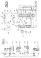
- FIGS 2, 3 and 5 to 11 show several different installations capable of implement such a method.
- Figures 2 and 3 relate to a installation close to that shown in Figure 1 from US-A-5,329,776, and differ from it only by the addition of an additional racking line 35 of liquid oxygen, of an additional pump 36 adapted to bring this liquid oxygen to the aforementioned pressure P, additional passages 37 of the exchange line thermal, for vaporization and reheating up to the ambient temperature of this oxygen, from a high oxygen storage buffer 38 pressure from the 12-passage pump circuit 17, from a pressure regulator 138 disposed upstream of this buffer, and a line 39 provided with an expansion valve 40, connecting this buffer to the consumer line 15.
- the air distillation installation shown in FIG. 3 essentially comprises: an air compressor 1; an apparatus 2 for purifying the compressed air into water and CO 2 by adsorption, this apparatus comprising two adsorption bottles 2A, 2B, one of which operates in adsorption while the other is being regenerated; a turbine-booster assembly 3 comprising an expansion turbine 4 and a booster 5 whose shafts are coupled; a heat exchanger 6 constituting the heat exchange line of the installation; a double distillation column 7 comprising a medium pressure column 8 surmounted by a low pressure column 9, with a vaporizer-condenser 10 putting the overhead vapor (nitrogen) from column 8 in heat exchange relation with the tank liquid (oxygen) from column 9; a liquid oxygen tank 11, the bottom of which is connected to a liquid oxygen pump 12; and a liquid nitrogen tank 13, the bottom of which is connected to a liquid nitrogen pump 14.
- This facility is intended to provide, via a user line 15, gaseous oxygen under the operating pressure P.
- liquid oxygen drawn from the column 9 tank via line 16 and stored in the reservoir 11 is brought to the high pressure P1 (30 bars) by the pump 12 in the liquid state, then vaporized and heated under this high pressure in passages 17 of the exchanger 6, under the conditions of FIG. 1 (c), and sent to buffer 38. Under the conditions of Figure 1 (d), this oxygen is expanded at 40 and sent to the line 15 via line 39.
- the heat necessary for this vaporization and to this reheating, as well as to reheating and possibly vaporization of other fluids drawn from the double column, is supplied by the air to be distilled, in the following conditions.
- All the air to be distilled is compressed by compressor 1 at a first high pressure significantly higher than the average column pressure 8 of use. Then the air, precooled in 18 and cooled to around room temperature in 19, is purified in one, 2A for example, of the bottles adsorption, and fully boosted by the booster 5, which is driven by the turbine 4.
- Air is then introduced at the hot end of exchanger 6 and completely cooled to a intermediate temperature. At this temperature, a fraction of the air continues to cool and is liquefied in passages 20 of the exchanger, then is relaxed at low pressure in an expansion valve 21 and introduced at an intermediate level in the column 9. The rest of the air is relaxed to average pressure in turbine 4 then sent directly, via a pipe 22, at the base of column 8.
- Low pressure nitrogen is heated in passages 28 of exchanger 6 then evacuated via a pipe 29, while the waste gas, after heating in passages 30 of the exchanger, is used to regenerate an adsorption bottle, the bottle 23 in the example considered, before being evacuated via a pipe 31.
- part medium pressure liquid nitrogen is, after expansion in an expansion valve 32, stored in the tank 13, and that a production of liquid nitrogen and / or oxygen liquid is supplied via line 33 (for nitrogen) and / or 34 (for oxygen).
- the pressure of the compressed air at 5 is the air condensation pressure by heat exchange with oxygen being vaporized under pressure of use P, i.e. the pressure for which air liquefaction knee 100, on the diagram heat exchange is located slightly to the right of the vertical bearing 101 for vaporizing oxygen under the pressure P ( Figure 4).
- the temperature difference at the end heat of the exchange line is adjusted by means of the turbine 4, the suction temperature of which is indicated in 102.
- pumps 12 and 36 can be connected in series, the pump suction 12 being stitched on the discharge pipe of the pump 36.
- Figure 5 shows a variant installation which differs from the previous one by the removal of pump 36 and of the vaporization-heating circuit corresponding.
- Figures 7 and 8 show another variant of the installation which does not differ from that of Figures 2 and 3 only by the fact that the oxygen at 16 bars is withdrawn in gaseous form from the column tank low pressure 9, via a line 44, heated under the low pressure in passages 45 of the exchange line 6, and brought to 16 bars by an oxygen compressor 46.
- Oxygen at 30 bar is withdrawn from the tank 11 by pump 12, which brings it to this high pressure in liquid form and then is vaporized and warmed in passages 17, and is sent directly to buffer 38.
- Figures 9 and 10 illustrate the implementation work of the invention with a conventional apparatus of air distillation without pump, nitrogen cycle (turbine 47 releasing at low pressure medium pressure nitrogen) and an argon separation column (not shown) coupled to the low pressure column by two lines 48.
- the oxygen flow D1 is withdrawn in gaseous form from the bottom column tank pressure and, after heating, is compressed to 16 bars and / or at 30 bars, under the conditions described above, by two respective oxygen compressors 49 and 50.
- the compressor 49 discharges directly into line 15, while compressor 50 backs up in buffer 38.
- Figures 11 and 12 The installation of Figures 11 and 12 does not differs from the previous one only in that the two oxygen compressors are connected in series instead to be mounted in parallel.
- the compressor 49 compresses the entire flow D1 to 16 bars, and the compressor 50 carries from 16 to 30 bars the flow d2 described next to Figure 1 (c).
- compressors 49 and 50 can be made up of two floors or groups stages of the same machine.
- operating pressure means the pressure in line 15. However, this does not exclude a subsequent modification of this pressure, for example by expansion.
- the pressure regulator 138 can be deleted.
- the buffer pressure then changes between pressures P and P1 as a function of time.
- the method of the invention can use multiple buffers at high pressures P1, P2, ... different, all significantly greater than the operating pressure P.
- gas is then taken from one or the other of the buffers, according to the variations of this flow.
Landscapes
- Engineering & Computer Science (AREA)
- Physics & Mathematics (AREA)
- Mechanical Engineering (AREA)
- Thermal Sciences (AREA)
- General Engineering & Computer Science (AREA)
- Health & Medical Sciences (AREA)
- Emergency Medicine (AREA)
- Separation By Low-Temperature Treatments (AREA)
Description
- on soutire ledit débit total sous forme liquide de l'appareil de distillation, et on le comprime sous cette forme par pompage avant de le vaporiser;
- on amène à la pression d'utilisation un premier débit de liquide au moyen d'une première pompe, on amène à la haute pression le débit destiné à la capacité-tampon au moyen d'une seconde pompe, et on vaporise chaque flux de liquide sous sa pression de pompage;
- on amène ledit débit total à la pression d'utilisation au moyen d'une pompe unique, on vaporise ce liquide et on porte à la haute pression la fraction du gaz ainsi obtenu qui est destinée à la capacité-tampon;
- on amène ledit débit total à la haute pression au moyen d'une pompe unique, on détend une fraction de ce débit total à la pression d'utilisation, et on vaporise les deux flux chacun sous sa pression;
- on soutire sous forme liquide de l'appareil de distillation un premier débit, on le comprime par pompage, et on le vaporise sous cette pression; et on soutire sous forme gazeuse de l'appareil de distillation le reste dudit débit total, et on le comprime sous cette forme;
- on soutire ledit débit total sous forme gazeuse de l'appareil de distillation, on comprime à la pression d'utilisation une fraction de ce gaz, et on comprime à la haute pression le débit complémentaire destiné à la capacité-tampon;
- on comprime chaque débit indépendamment à partir de la pression de soutirage de l'appareil de distillation;
- on comprime ledit débit total à la pression d'utilisation, et on comprime une fraction de ce premier débit de la pression d'utilisation à la haute pression.
- les premiers moyens comprennent une première pompe et des premiers moyens de vaporisation, et les seconds moyens comprennent une seconde pompe et des seconds moyens de vaporisation;
- les premiers moyens comprennent une pompe et des moyens de vaporisation, et les seconds moyens comprennent un compresseur dont l'aspiration est reliée à la sortie des moyens de vaporisation;
- les premiers moyens comprennent une pompe, une vanne de détente et des premiers moyens de vaporisation, et les seconds moyens comprennent des seconds moyens de vaporisation reliés au refoulement de la pompe;
- les premiers moyens comprennent un compresseur dont l'aspiration est reliée à un point de soutirage de gaz de l'appareil de distillation, et les seconds moyens comprennent une pompe et des moyens de vaporisation reliés au refoulement de cette pompe;
- les premiers et les seconds moyens comprennent respectivement deux compresseurs dont les aspirations sont reliées en parallèle à un point de soutirage de l'appareil de distillation ;
- les premiers moyens comprennent un premier compresseur dont l'aspiration est reliée à un point de soutirage de gaz de l'appareil de distillation, et les seconds moyens comprennent un second compresseur dont l'aspiration est reliée au refoulement du premier compresseur.
- la Figure 1 illustre le procédé de l'invention au moyen de quatre diagrammes (a) à (d);
- la Figure 2 représente très schématiquement une installation suivant l'invention;
- la Figure 3 représente la même installation de manière plus détaillée;
- la Figure 4 est un diagramme d'échange thermique correspondant à cette installation, avec en abscisses les températures (en °C) et en ordonnées les quantités de chaleur échangées;
- les Figures 5 et 6 sont des vues analogues à la Figure 2, relatives respectivement à deux variantes de l'installation;
- la Figure 7 est une vue analogue à la Figure 2 d'une autre variante de l'installation;
- la Figure 8 est une vue analogue à la Figure 3 correspondant à l'installation de la Figure 7;
- les Figures 9 et 10 d'une part, 11 et 12 d'autre part, représentent deux autres modes de réalisation de l'installation, de manière analogue aux Figures 2 et 3 respectivement.
- de t = 0 à t1, le débit demandé est nul ;
- de t1 à t2, le débit demandé est D1 ;
- de t2 à t3, le débit demandé est D2 > D1 ;
- de t3 à t4, le débit demandé est D3 > D2;
- de t4 à t5, le débit demandé est D4 < D1 ; et
- de t5 à T, le débit demandé est nul.
- de t = 0 à t1 : d1 = 0
- de t1 à t4, c'est-à-dire lorsque la demande en oxygène est supérieure ou égale à D1 : d1 = D1 ;
- de t4 à t5, c'est-à-dire lorsque la demande en oxygène est supérieure à 0 mais inférieure à D1 : d1 = D4;
- de t5 à T : d1 = 0.
- de t = 0 à t1 : d2 = D1 ;
- de t1 à t4 : d2 = 0;
- de t4 à t5 : d2 = D1 - D4 ;
- de t5 à T : d2 = D1.
- de t1 à t2 et de t4 à t5, uniquement par la production d'oxygène sous 16 bars, et
- de t2 à t4, partiellement par cette production sous 16 bars et partiellement par de l'oxygène prélevé dans la capacité-tampon et détendu.
- la boíte froide 41 de l'installation, qui en contient les parties cryogéniques;
- les deux pompes à oxygène liquide 12 et 36, lesquelles, en pratique, sont bien entendu contenues dans la boíte froide; et
- la conduite consommatrice 15, le buffer 38, la ligne 39 et la vanne de détente 40.
Claims (16)
- Procédé pour fournir à une conduite consommatrice (15), pendant un intervalle de temps (O, T), un débit demandé variable (D) d'un constituant de l'air, notamment d'oxygène, produit par un appareil de distillation d'air (7), dans lequel :caractérisé en ce que l'on réchauffe ledit débit total jusqu'au bout chaud de la ligne d'échange et on envoie le débit de stockage du bout chaud à la capacité-tampon.on refroidit de l'air destiné à la distillation dans une ligne d'échange (6).on soutire de l'appareil (7) un débit total dudit constituant de valeur constante (D1) ;on divise l'intervalle de temps (O, T) en plusieurs types de périodes, à savoir :éventuellement, au moins une première période (t1 à t2) pendant laquelle le débit demandé (D) est égal audit débit total (D1) ;au moins une deuxième période (0 à t1, t4 à T) pendant laquelle le débit demandé (D) est inférieur audit débit total (D1) etau moins une troisième période (t2 à t4) pendant laquelle le débit demandé (D) est supérieur audit débit total (D1) ;pendant ladite ou lesdites premières périodes, on amène ledit débit total (D1) à la pression d'utilisation (P), et on l'envoie à la conduite consommatrice (15);pendant ladite ou lesdites deuxièmes périodes :on amène le débit demandé (D) à la pression d'utilisation, et on l'envoie à la conduite consommatrice (15); eton amène à une haute pression (P1) supérieure à la pression d'utilisation (P) un débit de stockage (d2) dudit constituant égal à la différence entre ledit débit total (D1) et le débit demandé (D), et on stocke ce débit de stockage dans au moins une capacité-tampon (38); etpendant ladite ou lesdites troisièmes périodes :on amène ledit débit total (D1) à la pression d'utilisation (P), et on l'envoie à la conduite consommatrice (15); eton envoie en outre dans la conduite consommatrice (15) un débit complémentaire (d3) dudit constituant égal à la différence entre le débit demandé (D) et ledit débit total (D1), ce débit complémentaire étant prélevé dans au moins une capacité-tampon (38) et détendu à la pression d'utilisation (P)
- Procédé suivant la revendication 1, caractérisé en ce qu'on soutire ledit débit total (D1) sous forme liquide de l'appareil de distillation (7), et on le comprime sous cette forme par pompage (en 12, 36) avant de le vaporiser (en 6).
- Procédé suivant la revendication 2,
caractérisé en ce qu'on amène à la pression d'utilisation (P) un premier débit de liquide au moyen d'une première pompe (12), on amène à la haute pression (P1) le débit destiné à la capacité-tampon(38) au moyen d'une seconde pompe (36), et on vaporise (en 17, 37) chaque flux de liquide sous sa pression de pompage (Figures 2 et 3). - Procédé suivant la revendication 2, caractérisé en ce qu'on amène ledit débit total (D1) à la pression d'utilisation (P) au moyen d'une pompe unique (12), on vaporise ce liquide (en 17) et on porte à la haute pression (P1) la fraction du gaz ainsi obtenu qui est destinée à la capacité-tampon (38) (Figure 5).
- Procédé suivant la revendication 2, caractérisé en ce qu'on amène ledit débit total (D1) à la haute pression (P1) au moyen d'une pompe unique (12), on détend (en 143) une fraction de ce débit total à la pression d'utilisation (P), et on vaporise les deux flux chacun sous sa pression (Figure 6).
- Procédé suivant la revendication 1, caractérisé en ce qu'on soutire sous forme liquide de l'appareil de distillation (7) un premier des deux débits, on le comprime par pompage (en 12), et on le vaporise sous cette pression (en 17); et on soutire sous forme gazeuse de l'appareil de distillation le reste dudit débit total, et on le comprime sous cette forme (en 46) (Figures 7 et 8).
- Procédé suivant la revendication 1, caractérisé en ce qu'on soutire ledit débit total (D1) sous forme gazeuse de l'appareil de distillation (7), on comprime à la pression d'utilisation (P) une fraction (d1) de ce gaz, et on comprime à la haute pression (P1) (en 50) le débit complémentaire (d2) destiné à la capacité-tampon (38) (Figures 9 à 12).
- Procédé suivant la revendication 7, caractérisé en ce qu'on comprime chaque débit indépendamment à partir de la pression de soutirage de l'appareil de distillation (7) (Figures 9 et 10).
- Procédé suivant la revendication 7, caractérisé en ce qu'on comprime ledit débit total (D1) à la pression d'utilisation (P), et on comprime une fraction de ce premier débit de la pression (P) d'utilisation à la haute pression (P1) (Figures 11 et 12).
- Installation de distillation d'air destinée à fournir à une conduite consommatrice (15) un débit variable d'un constituant de l'air, notamment d'oxygène, comprenant une ligne d'échange (6) où on refroidit l'air destiné à la distillation des moyens pour soutirer de l'appareil de distillation (7) un débit total constant (D1) dudit constituant ; une capacité-tampon (38); des premiers moyens pour amener une partie au moins dudit débit total (D1) à la pression d'utilisation (P) et sous forme gazeuse, ces premiers moyens étant reliés à la conduite consommatrice (15); des seconds moyens pour amener un second débit (d2) dudit constituant à une haute pression (P1) supérieure à la pression d'utilisation (P) et sous forme gazeuse, ces seconds moyens étant reliés à la capacité-tampon (38); et une conduite auxiliaire (39) munie d'une vanne de détente commandée (40), reliant la capacité-tampon à la éconduite consommatrice (15)
caracterisée en ce que la capacité-tampon se trouve en aval du bout chaud de la ligne d'échange. - Installation suivant la revendication 10, caractérisée en ce que les premiers moyens comprennent une première pompe (12) et des premiers moyens de vaporisation (17), et en ce que les seconds moyens comprennent une seconde pompe (36) et des seconds moyens de vaporisation (37) (Figures 2 et 3).
- Installation suivant la revendication 10, caractérisée en ce que les premiers moyens comprennent une pompe (12) et des moyens de vaporisation (17), et en ce que les seconds moyens comprennent un compresseur (43) dont l'aspiration est reliée à la sortie des moyens de vaporisation (Figure 5).
- Installation suivant la revendication 10, caractérisée en ce que les premiers moyens comprennent une pompe (12), une vanne de détente (143) et des premiers moyens de vaporisation (17), et en ce que les seconds moyens comprennent des seconds moyens de vaporisation (37) reliés au refoulement de la pompe (Figure 6).
- Installation suivant la revendication 10, caractérisée en ce que les premiers moyens comprennent un compresseur (46) dont l'aspiration est reliée à un point de soutirage de gaz de l'appareil de distillation (7), et en ce que les seconds moyens comprennent une pompe (12) et des moyens de vaporisation (17) reliés au refoulement de cette pompe (Figures 7 et 8).
- Installation suivant la revendication 10, caractérisé en ce que les premiers et les seconds moyens comprennent respectivement deux compresseurs (49, 50) dont les aspirations sont reliées en parallèle à un point de soutirage de l'appareil de distillation (7) (Figures 9 et 10).
- Installation suivant la revendication 10, caractérisé en ce que les premiers moyens comprennent un premier compresseur (49) dont l'aspiration est reliée à un point de soutirage de gaz de l'appareil de distillation (7), et en ce que les seconds moyens comprennent un second compresseur (50) dont l'aspiration est reliée au refoulement du premier compresseur (Figures 11 et 12).
Applications Claiming Priority (2)
| Application Number | Priority Date | Filing Date | Title |
|---|---|---|---|
| FR9615281A FR2757282B1 (fr) | 1996-12-12 | 1996-12-12 | Procede et installation de fourniture d'un debit variable d'un gaz de l'air |
| FR9615281 | 1996-12-12 |
Publications (2)
| Publication Number | Publication Date |
|---|---|
| EP0848220A1 EP0848220A1 (fr) | 1998-06-17 |
| EP0848220B1 true EP0848220B1 (fr) | 2004-02-18 |
Family
ID=9498600
Family Applications (1)
| Application Number | Title | Priority Date | Filing Date |
|---|---|---|---|
| EP97402990A Revoked EP0848220B1 (fr) | 1996-12-12 | 1997-12-10 | Procédé et installation de fourniture d'un débit variable d'un gaz de l'air |
Country Status (13)
| Country | Link |
|---|---|
| US (1) | US5941098A (fr) |
| EP (1) | EP0848220B1 (fr) |
| JP (1) | JPH10259990A (fr) |
| KR (1) | KR100474464B1 (fr) |
| CN (1) | CN1130538C (fr) |
| AR (1) | AR008937A1 (fr) |
| BR (1) | BR9705641A (fr) |
| CA (1) | CA2224742A1 (fr) |
| DE (1) | DE69727648T2 (fr) |
| ES (1) | ES2216119T3 (fr) |
| FR (1) | FR2757282B1 (fr) |
| PL (1) | PL323709A1 (fr) |
| ZA (1) | ZA9711131B (fr) |
Families Citing this family (26)
| Publication number | Priority date | Publication date | Assignee | Title |
|---|---|---|---|---|
| FR2751737B1 (fr) * | 1996-07-25 | 1998-09-11 | Air Liquide | Procede et installation de production d'un gaz de l'air a debit variable |
| DE19732887A1 (de) * | 1997-07-30 | 1999-02-04 | Linde Ag | Verfahren zur Luftzerlegung |
| DE10013075A1 (de) * | 2000-03-17 | 2001-09-20 | Linde Ag | Verfahren zur Gewinnung von gasförmigem und flüssigem Stickstoff mit variablem Anteil des Flüssigprodukts |
| US6357259B1 (en) * | 2000-09-29 | 2002-03-19 | The Boc Group, Inc. | Air separation method to produce gaseous product |
| EP1207362A1 (fr) * | 2000-10-23 | 2002-05-22 | Air Products And Chemicals, Inc. | Procédé et appareil pour la production d'oxygène gazeux à basse pression |
| EP1202013B3 (fr) * | 2000-10-23 | 2009-04-01 | Air Products And Chemicals, Inc. | Procédé et dispositif de production d'oxygène gazeux à basse pression |
| GB0219415D0 (en) * | 2002-08-20 | 2002-09-25 | Air Prod & Chem | Process and apparatus for cryogenic separation process |
| FR2854683B1 (fr) * | 2003-05-05 | 2006-09-29 | Air Liquide | Procede et installation de production de gaz de l'air sous pression par distillation cryogenique d'air |
| FR2872262B1 (fr) * | 2004-06-29 | 2010-11-26 | Air Liquide | Procede et installation de fourniture de secours d'un gaz sous pression |
| US7409835B2 (en) * | 2004-07-14 | 2008-08-12 | Air Liquide Process & Construction, Inc. | Backup system and method for production of pressurized gas |
| AU2005225027A1 (en) * | 2005-07-21 | 2007-02-08 | L'air Liquide Societe Anonyme Pour L'etude Et L"Exploitation Des Procedes Georges Claude | Process and apparatus for the separation of air by cryogenic distillation |
| FR2895068B1 (fr) * | 2005-12-15 | 2014-01-31 | Air Liquide | Procede de separation d'air par distillation cryogenique |
| JP4688843B2 (ja) * | 2007-05-07 | 2011-05-25 | 株式会社神戸製鋼所 | 空気分離装置 |
| US7821158B2 (en) * | 2008-05-27 | 2010-10-26 | Expansion Energy, Llc | System and method for liquid air production, power storage and power release |
| CN101769438A (zh) * | 2008-12-30 | 2010-07-07 | 湖北宜化化工股份有限公司 | 进出气柜气体近路运行的方法 |
| US8623107B2 (en) | 2009-02-17 | 2014-01-07 | Mcalister Technologies, Llc | Gas hydrate conversion system for harvesting hydrocarbon hydrate deposits |
| JP5407661B2 (ja) * | 2009-08-26 | 2014-02-05 | Jfeスチール株式会社 | 酸素供給設備及び酸素供給方法 |
| CN102072612B (zh) * | 2010-10-19 | 2013-05-29 | 上海加力气体有限公司 | N型模式节能制气方法 |
| CN103575064B (zh) * | 2012-07-23 | 2015-10-28 | 中国石油化工股份有限公司 | 一种空气分离氧氮气快速增加压力氮气负荷的装置及方法 |
| US9631863B2 (en) * | 2013-03-12 | 2017-04-25 | Mcalister Technologies, Llc | Liquefaction systems and associated processes and methods |
| US8907524B2 (en) | 2013-05-09 | 2014-12-09 | Expansion Energy Llc | Systems and methods of semi-centralized power storage and power production for multi-directional smart grid and other applications |
| CN105637310B (zh) | 2013-10-23 | 2017-08-22 | 普莱克斯技术有限公司 | 氧后备方法及系统 |
| US20150168056A1 (en) * | 2013-12-17 | 2015-06-18 | L'air Liquide, Societe Anonyme Pour L'etude Et L'exploitation Des Procedes Georges Claude | Method For Producing Pressurized Gaseous Oxygen Through The Cryogenic Separation Of Air |
| US20160025408A1 (en) * | 2014-07-28 | 2016-01-28 | Zhengrong Xu | Air separation method and apparatus |
| DE102016004606A1 (de) * | 2016-04-14 | 2017-10-19 | Linde Aktiengesellschaft | Verfahrenstechnische Anlage und Verfahren zur Flüssiggasherstellung |
| US10260801B2 (en) * | 2016-06-30 | 2019-04-16 | L'air Liquide Societe Anonyme Pour L'etude Et L'exploitation Des Procedes George Claude | Method for operating an air separation plant |
Family Cites Families (9)
| Publication number | Priority date | Publication date | Assignee | Title |
|---|---|---|---|---|
| US3319434A (en) * | 1966-03-14 | 1967-05-16 | Air Reduction | Low temperature refrigeration and gas storage |
| JPS61190277A (ja) * | 1985-02-16 | 1986-08-23 | 大同酸素株式会社 | 高純度窒素および酸素ガス製造装置 |
| AT387454B (de) * | 1986-05-14 | 1989-01-25 | Voest Alpine Ag | Einrichtung zum zerlegen von luft mit speicherung von produktgas in fluessiger form |
| DE3913880A1 (de) * | 1989-04-27 | 1990-10-31 | Linde Ag | Verfahren und vorrichtung zur tieftemperaturzerlegung von luft |
| FR2670278B1 (fr) * | 1990-12-06 | 1993-01-22 | Air Liquide | Procede et installation de distillation d'air en regime variable de production d'oxygene gazeux. |
| US5224336A (en) * | 1991-06-20 | 1993-07-06 | Air Products And Chemicals, Inc. | Process and system for controlling a cryogenic air separation unit during rapid changes in production |
| FR2697620B1 (fr) * | 1992-10-30 | 1994-12-23 | Air Liquide | Procédé et installation de production d'azote gazeux à débit variable. |
| FR2706195B1 (fr) * | 1993-06-07 | 1995-07-28 | Air Liquide | Procédé et unité de fourniture d'un gaz sous pression à une installation consommatrice d'un constituant de l'air. |
| FR2716816B1 (fr) * | 1994-03-02 | 1996-05-03 | Air Liquide | Procédé de redémarrage d'une colonne auxiliaire de séparation argon/oxygène par distillation, et installation correspondante. |
-
1996
- 1996-12-12 FR FR9615281A patent/FR2757282B1/fr not_active Expired - Fee Related
-
1997
- 1997-12-10 ZA ZA9711131A patent/ZA9711131B/xx unknown
- 1997-12-10 EP EP97402990A patent/EP0848220B1/fr not_active Revoked
- 1997-12-10 DE DE69727648T patent/DE69727648T2/de not_active Revoked
- 1997-12-10 ES ES97402990T patent/ES2216119T3/es not_active Expired - Lifetime
- 1997-12-11 JP JP9341721A patent/JPH10259990A/ja active Pending
- 1997-12-11 AR ARP970105832A patent/AR008937A1/es unknown
- 1997-12-11 BR BR9705641A patent/BR9705641A/pt not_active IP Right Cessation
- 1997-12-12 CN CN97125391.9A patent/CN1130538C/zh not_active Expired - Fee Related
- 1997-12-12 US US08/990,085 patent/US5941098A/en not_active Expired - Fee Related
- 1997-12-12 PL PL97323709A patent/PL323709A1/xx unknown
- 1997-12-12 CA CA002224742A patent/CA2224742A1/fr not_active Abandoned
- 1997-12-15 KR KR1019970066873A patent/KR100474464B1/ko not_active Expired - Fee Related
Also Published As
| Publication number | Publication date |
|---|---|
| CN1130538C (zh) | 2003-12-10 |
| CA2224742A1 (fr) | 1998-06-12 |
| AR008937A1 (es) | 2000-02-23 |
| JPH10259990A (ja) | 1998-09-29 |
| DE69727648D1 (de) | 2004-03-25 |
| ZA9711131B (en) | 1998-06-23 |
| KR100474464B1 (ko) | 2005-06-17 |
| FR2757282A1 (fr) | 1998-06-19 |
| US5941098A (en) | 1999-08-24 |
| FR2757282B1 (fr) | 2006-06-23 |
| ES2216119T3 (es) | 2004-10-16 |
| BR9705641A (pt) | 1999-05-25 |
| PL323709A1 (en) | 1998-06-22 |
| CN1190726A (zh) | 1998-08-19 |
| KR19980063916A (ko) | 1998-10-07 |
| EP0848220A1 (fr) | 1998-06-17 |
| DE69727648T2 (de) | 2004-10-14 |
Similar Documents
| Publication | Publication Date | Title |
|---|---|---|
| EP0848220A1 (fr) | Procédé et installation de fourniture d'un débit variable d'un gaz de l'air | |
| EP0628778B1 (fr) | Procédé et unité de fourniture d'un gaz sous pression à une installation consommatrice d'un constituant de l'air | |
| EP0504029B1 (fr) | Procédé de production d'oxygène gazeux sous pression | |
| EP0576314B1 (fr) | Procédé et installation de production d'oxygène gazeux sous pression | |
| EP0689019B1 (fr) | Procédé et installation de production d'oxygène gazeux sous pression | |
| EP1447634B1 (fr) | Procédé et installation de production sous forme gazeuse et sous haute pression d'au moins un fluide choisi parmi l'oxygène, l'argon et l'azote par distillation cryogénique de l'air | |
| EP0605262B1 (fr) | Procédé et installation de production d'oxygène gazeux sous pression | |
| WO2007068858A2 (fr) | Procédé de séparation d'air par distillation cryogénique | |
| EP0789208A1 (fr) | Procédé et installation de production d'oxygène gazeux sous haute pression | |
| EP0489617B1 (fr) | Procédé et installation de distillation d'air en régime variable de production d'oxygène gazeux | |
| CA2154984A1 (fr) | Procede et installation de production d'oxygene gazeux sous pression a debit variable | |
| WO2012131231A2 (fr) | Procede de separation d'air par distillation cryogenique | |
| EP0914584B1 (fr) | Procede et installation de production d'un gaz de l'air a debit variable | |
| WO1999054673A1 (fr) | Procede et installation de distillation d'air avec production d'argon | |
| FR2688052A1 (fr) | Procede et installation de production d'oxygene et/ou d'azote gazeux sous pression par distillation d'air. | |
| EP0611218B2 (fr) | Procédé et installation de production d'oxygene sous pression | |
| EP0678317B1 (fr) | Procédé et installation de séparation d'un mélange gazeux par distillation cryogénique | |
| FR2929697A1 (fr) | Procede de production d'azote gazeux variable et d'oxygene gazeux variable par distillation d'air | |
| EP1697690A2 (fr) | Procede et installation d enrichissement d'un flux gazeux en l'un de ses constituants | |
| EP1409937B1 (fr) | Procede de production de vapeur d'eau et de distillation d'air | |
| FR2674011A1 (fr) | Procede et installation de production d'oxygene gazeux sous pression. | |
| FR2685460A1 (fr) | Procede et installation de production d'oxygene gazeux sous pression par distillation d'air. | |
| FR2787562A1 (fr) | Procede et installation de distillation d'air avec production d'argon |
Legal Events
| Date | Code | Title | Description |
|---|---|---|---|
| PUAI | Public reference made under article 153(3) epc to a published international application that has entered the european phase |
Free format text: ORIGINAL CODE: 0009012 |
|
| AK | Designated contracting states |
Kind code of ref document: A1 Designated state(s): BE DE ES GB IT NL SE |
|
| AX | Request for extension of the european patent |
Free format text: AL;LT;LV;MK;RO;SI |
|
| 17P | Request for examination filed |
Effective date: 19981217 |
|
| AKX | Designation fees paid |
Free format text: BE DE ES GB IT NL SE |
|
| RBV | Designated contracting states (corrected) |
Designated state(s): BE DE ES GB IT NL SE |
|
| 17Q | First examination report despatched |
Effective date: 20000901 |
|
| RAP1 | Party data changed (applicant data changed or rights of an application transferred) |
Owner name: L'AIR LIQUIDE, S.A. A DIRECTOIRE ET CONSEIL DE SUR |
|
| GRAH | Despatch of communication of intention to grant a patent |
Free format text: ORIGINAL CODE: EPIDOS IGRA |
|
| GRAS | Grant fee paid |
Free format text: ORIGINAL CODE: EPIDOSNIGR3 |
|
| GRAA | (expected) grant |
Free format text: ORIGINAL CODE: 0009210 |
|
| AK | Designated contracting states |
Kind code of ref document: B1 Designated state(s): BE DE ES GB IT NL SE |
|
| REG | Reference to a national code |
Ref country code: GB Ref legal event code: FG4D Free format text: NOT ENGLISH |
|
| REF | Corresponds to: |
Ref document number: 69727648 Country of ref document: DE Date of ref document: 20040325 Kind code of ref document: P |
|
| REG | Reference to a national code |
Ref country code: SE Ref legal event code: TRGR |
|
| GBT | Gb: translation of ep patent filed (gb section 77(6)(a)/1977) |
Effective date: 20040506 |
|
| REG | Reference to a national code |
Ref country code: ES Ref legal event code: FG2A Ref document number: 2216119 Country of ref document: ES Kind code of ref document: T3 |
|
| PLBQ | Unpublished change to opponent data |
Free format text: ORIGINAL CODE: EPIDOS OPPO |
|
| PLBI | Opposition filed |
Free format text: ORIGINAL CODE: 0009260 |
|
| PLAX | Notice of opposition and request to file observation + time limit sent |
Free format text: ORIGINAL CODE: EPIDOSNOBS2 |
|
| 26 | Opposition filed |
Opponent name: LINDE AKTIENGESELLSCHAFT Effective date: 20041112 Opponent name: PRAXAIR, INC. Effective date: 20041109 |
|
| NLR1 | Nl: opposition has been filed with the epo |
Opponent name: LINDE AKTIENGESELLSCHAFT Opponent name: PRAXAIR, INC. |
|
| PLAX | Notice of opposition and request to file observation + time limit sent |
Free format text: ORIGINAL CODE: EPIDOSNOBS2 |
|
| PLBB | Reply of patent proprietor to notice(s) of opposition received |
Free format text: ORIGINAL CODE: EPIDOSNOBS3 |
|
| RDAF | Communication despatched that patent is revoked |
Free format text: ORIGINAL CODE: EPIDOSNREV1 |
|
| PGFP | Annual fee paid to national office [announced via postgrant information from national office to epo] |
Ref country code: GB Payment date: 20061114 Year of fee payment: 10 |
|
| PGFP | Annual fee paid to national office [announced via postgrant information from national office to epo] |
Ref country code: NL Payment date: 20061117 Year of fee payment: 10 |
|
| PGFP | Annual fee paid to national office [announced via postgrant information from national office to epo] |
Ref country code: SE Payment date: 20061121 Year of fee payment: 10 |
|
| PGFP | Annual fee paid to national office [announced via postgrant information from national office to epo] |
Ref country code: DE Payment date: 20061124 Year of fee payment: 10 |
|
| PGFP | Annual fee paid to national office [announced via postgrant information from national office to epo] |
Ref country code: BE Payment date: 20061204 Year of fee payment: 10 |
|
| PGFP | Annual fee paid to national office [announced via postgrant information from national office to epo] |
Ref country code: ES Payment date: 20061213 Year of fee payment: 10 |
|
| RDAG | Patent revoked |
Free format text: ORIGINAL CODE: 0009271 |
|
| STAA | Information on the status of an ep patent application or granted ep patent |
Free format text: STATUS: PATENT REVOKED |
|
| 27W | Patent revoked |
Effective date: 20061011 |
|
| GBPR | Gb: patent revoked under art. 102 of the ep convention designating the uk as contracting state |
Free format text: 20061011 |
|
| REG | Reference to a national code |
Ref country code: SE Ref legal event code: ECNC |
|
| NLR2 | Nl: decision of opposition |
Effective date: 20061011 |
|
| PGFP | Annual fee paid to national office [announced via postgrant information from national office to epo] |
Ref country code: IT Payment date: 20071121 Year of fee payment: 11 |